EP1914838A1 - Interrupteur d'installation modulaire - Google Patents
Interrupteur d'installation modulaire Download PDFInfo
- Publication number
- EP1914838A1 EP1914838A1 EP07018999A EP07018999A EP1914838A1 EP 1914838 A1 EP1914838 A1 EP 1914838A1 EP 07018999 A EP07018999 A EP 07018999A EP 07018999 A EP07018999 A EP 07018999A EP 1914838 A1 EP1914838 A1 EP 1914838A1
- Authority
- EP
- European Patent Office
- Prior art keywords
- terminal
- connection
- switching device
- clamping
- conductor
- Prior art date
- Legal status (The legal status is an assumption and is not a legal conclusion. Google has not performed a legal analysis and makes no representation as to the accuracy of the status listed.)
- Withdrawn
Links
Images
Classifications
-
- H—ELECTRICITY
- H01—ELECTRIC ELEMENTS
- H01R—ELECTRICALLY-CONDUCTIVE CONNECTIONS; STRUCTURAL ASSOCIATIONS OF A PLURALITY OF MUTUALLY-INSULATED ELECTRICAL CONNECTING ELEMENTS; COUPLING DEVICES; CURRENT COLLECTORS
- H01R9/00—Structural associations of a plurality of mutually-insulated electrical connecting elements, e.g. terminal strips or terminal blocks; Terminals or binding posts mounted upon a base or in a case; Bases therefor
- H01R9/22—Bases, e.g. strip, block, panel
- H01R9/24—Terminal blocks
- H01R9/26—Clip-on terminal blocks for side-by-side rail- or strip-mounting
-
- H—ELECTRICITY
- H01—ELECTRIC ELEMENTS
- H01R—ELECTRICALLY-CONDUCTIVE CONNECTIONS; STRUCTURAL ASSOCIATIONS OF A PLURALITY OF MUTUALLY-INSULATED ELECTRICAL CONNECTING ELEMENTS; COUPLING DEVICES; CURRENT COLLECTORS
- H01R4/00—Electrically-conductive connections between two or more conductive members in direct contact, i.e. touching one another; Means for effecting or maintaining such contact; Electrically-conductive connections having two or more spaced connecting locations for conductors and using contact members penetrating insulation
- H01R4/28—Clamped connections, spring connections
- H01R4/48—Clamped connections, spring connections utilising a spring, clip, or other resilient member
- H01R4/4809—Clamped connections, spring connections utilising a spring, clip, or other resilient member using a leaf spring to bias the conductor toward the busbar
- H01R4/48185—Clamped connections, spring connections utilising a spring, clip, or other resilient member using a leaf spring to bias the conductor toward the busbar adapted for axial insertion of a wire end
- H01R4/4819—Clamped connections, spring connections utilising a spring, clip, or other resilient member using a leaf spring to bias the conductor toward the busbar adapted for axial insertion of a wire end the spring shape allowing insertion of the conductor end when the spring is unbiased
- H01R4/4821—Single-blade spring
-
- H—ELECTRICITY
- H01—ELECTRIC ELEMENTS
- H01R—ELECTRICALLY-CONDUCTIVE CONNECTIONS; STRUCTURAL ASSOCIATIONS OF A PLURALITY OF MUTUALLY-INSULATED ELECTRICAL CONNECTING ELEMENTS; COUPLING DEVICES; CURRENT COLLECTORS
- H01R4/00—Electrically-conductive connections between two or more conductive members in direct contact, i.e. touching one another; Means for effecting or maintaining such contact; Electrically-conductive connections having two or more spaced connecting locations for conductors and using contact members penetrating insulation
- H01R4/28—Clamped connections, spring connections
- H01R4/48—Clamped connections, spring connections utilising a spring, clip, or other resilient member
- H01R4/4809—Clamped connections, spring connections utilising a spring, clip, or other resilient member using a leaf spring to bias the conductor toward the busbar
- H01R4/4846—Busbar details
- H01R4/485—Single busbar common to multiple springs
-
- H—ELECTRICITY
- H01—ELECTRIC ELEMENTS
- H01R—ELECTRICALLY-CONDUCTIVE CONNECTIONS; STRUCTURAL ASSOCIATIONS OF A PLURALITY OF MUTUALLY-INSULATED ELECTRICAL CONNECTING ELEMENTS; COUPLING DEVICES; CURRENT COLLECTORS
- H01R4/00—Electrically-conductive connections between two or more conductive members in direct contact, i.e. touching one another; Means for effecting or maintaining such contact; Electrically-conductive connections having two or more spaced connecting locations for conductors and using contact members penetrating insulation
- H01R4/28—Clamped connections, spring connections
- H01R4/48—Clamped connections, spring connections utilising a spring, clip, or other resilient member
- H01R4/4809—Clamped connections, spring connections utilising a spring, clip, or other resilient member using a leaf spring to bias the conductor toward the busbar
- H01R4/484—Spring housing details
- H01R4/4842—Spring housing details the spring housing being provided with a single opening for insertion of a spring-activating tool
-
- H—ELECTRICITY
- H01—ELECTRIC ELEMENTS
- H01R—ELECTRICALLY-CONDUCTIVE CONNECTIONS; STRUCTURAL ASSOCIATIONS OF A PLURALITY OF MUTUALLY-INSULATED ELECTRICAL CONNECTING ELEMENTS; COUPLING DEVICES; CURRENT COLLECTORS
- H01R9/00—Structural associations of a plurality of mutually-insulated electrical connecting elements, e.g. terminal strips or terminal blocks; Terminals or binding posts mounted upon a base or in a case; Bases therefor
- H01R9/22—Bases, e.g. strip, block, panel
- H01R9/24—Terminal blocks
- H01R9/2408—Modular blocks
Definitions
- the invention relates to a modular service switching device having a housing, with a front and rear front, with the front and rear front sides connecting front and rear narrow sides, with lateral broad sides, with a mounting side, with at least one fixed in a terminal connection space inside the housing, screwless Terminal connection for connecting connecting conductors by clamping with acting as a compression spring on the terminal conductor ends and this clamped in a window-like recess of a busbar clamping spring, which has a number of terminal to be connected corresponding number of sub-springs, according to the preamble of claim 1.
- a generic service switching device may, for example, be a circuit breaker which comprises within its housing at least one contact point with at least one fixed contact piece and one movable contact piece via which a current path leading from an input to an output terminal can be opened and closed.
- the contact point is generally operated by a rear derailleur with Verklinkungsstelle.
- Such a circuit breaker may further comprise tripping devices, such as a thermal trip or a magnetic quick release, when a short circuit occurs or fault current in the current path on the contact point or the switching mechanism act, so that the contact point is opened.
- auxiliary switch for attachment to a circuit breaker.
- Such add - on auxiliary switches are switched simultaneously with the main poles and are used to switch off or switch on circuits. They can serve many purposes, for example, to switch optical or acoustic signals indicating the switching state of the main circuit.
- Auxiliary switches can have several auxiliary contacts in separate current paths, which are galvanically isolated from one another, and to which one or two connection conductors can be connected at the input and output ends.
- the add-on auxiliary switches usually require only a width of half the standard module width, that is about 8.75 mm.
- screw terminals are used in generic service switching devices.
- Clamping elements can be plug-in terminals or spring-loaded terminals. In principle, these can greatly simplify the connection of connecting conductors, since during assembly no longer has to be fastened with a screwdriver a screw, but the connection conductor can be easily inserted into the terminal, he is then held by the terminal element itself. If more than one connection conductor is to be connected by means of a clamping element, each of the connection conductors must be able to be inserted and also removed again without influencing the other one.
- a terminal connection is known in which a plurality of insertion openings are present in a contact frame.
- the clamping spring is divided at its free end by one or more slot-shaped recesses in a number of plug openings corresponding number finger-like extensions.
- Each of the extensions is guided through in each case one of the insertion openings and in each of the insertion openings of each one of the extensions a conductor clamped.
- each connection conductor can be inserted and removed without affecting the other connection conductors.
- a terminal connection For a current connection from a clamped connection conductor to an outgoing conductor inside the device, a terminal connection must comply with the EP 1 575 130 only a narrow bridge on the contact frame available.
- the contact resistance from the clamped connecting conductor to the further electrical outgoing conductor into the switching device is correspondingly high. Since a separate connection window, separated by a crossbar, is available for each connection conductor to be clamped, the terminal connection is made in accordance with the EP 1 575 130 so wide that it does not fit into switching devices with only half the standard module width.
- the housing wall in the region of the terminal connection one of the number to be connected terminal conductor corresponding number of connection openings for each connection conductor, and each connection opening is associated with a part spring so that Each connection conductor can be clamped with the other connection conductors against a common clamping edge only a window-like recess.
- connection conductors can be introduced independently of each other in the one, common window-like recess.
- each connection opening is assigned an insertion channel for guiding the connecting conductor to be connected to this connection opening.
- connection openings of each terminal connection space can advantageously be assigned at least one engagement opening for an actuating tool for actuating at least one of the torsion springs of the clamping spring. This makes it possible to remove the lead once inserted again, namely, by removing the part spring is bent so far by means of the actuating tool that the connection conductor can be pulled out. Even when inserting connecting conductors with flexible conductor ends, the part spring is first opened by means of the actuating tool, and released again after the insertion of the flexible conductor end.
- a service switching device may also have two or more terminal connections in two or more terminal connection spaces.
- the two or more terminal connection spaces are then arranged in a common plane parallel to the broad side and the height above the mounting side against each other in the housing. In this way it is possible to accommodate a plurality of terminal connections in a service switching device according to the invention so that they are electrically isolated from each other.
- connection opening assigned to a first terminal connection is then in a rear front side, and the connection openings assigned to a second or further terminal connection are provided in the narrow side of the housing adjoining the rear front side.
- the connection openings assigned to a second or further terminal connection are provided in the narrow side of the housing adjoining the rear front side.
- the busbar of the terminal connection comprises a connection end and an adjoining discharge region.
- the window-like recess in the busbar has a support edge and a clamping edge opposite the support edge at the transition of the connection end into the discharge region.
- the clamping spring has a support leg, with which it is supported on the support edge of the busbar.
- a curved piece and thereon a longitudinally slotted clamping leg, so that two independent klemmpote part springs are formed, which are associated with a connection opening, and thereby each a conductor end between a part spring and the clamping edge is clamped as an abutment.
- the conductor end can advantageously be inserted into the window-like recess from the side of the curved piece.
- the busbar approximately in a U-shape, wherein the terminal end forms the one U-leg, and the diverting region is formed by a transverse web and the other U-legs.
- a Aufkantung may be provided for securing further current conductors.
- a discharge can be formed.
- the discharge bar may advantageously extend approximately perpendicular to the other U-leg, and the clamping edge of the opposite side of the connection end may be supported on the discharge. This makes an even more compact and inherently more stable design of the terminal connection possible, even with a half-module housing width.
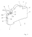
- the insulating housing 3 has a front front side 4, rear front sides 5, 5 ', a fastening or connection side 6, on which a recess is provided with a nose, by means of which the service switching device 1 on a standard profile support rail, for example on a top hat rail, next to another Installation switching device can be snapped, and broadsides 9, of which in the view of Figure 1 only one is shown.
- the rear front sides 5, 5 ' are connected via rear narrow sides 8, 8' to the attachment side 6, and the front front side 4 is connected via front narrow sides 7, 7 'to the rear front sides 5, 5'.
- connection conductor 14 is shown inserted into the connection opening 23.
- the two connection openings 23, 25 are assigned to a first terminal connection space 18, which is located in the interior of the housing and not visible in FIG. 1, with a first screwless terminal connection 10 (see FIG. 2).
- a rectangular engagement opening 218 is introduced into the housing wall, here into the rear front side 5. This opens a first engagement channel 219, through which the two connection openings in the first terminal connection space 18 pass through with a screwdriver as an actuation tool 23,25 associated clamping spring 12 can be actuated.
- connection openings 26,27 are introduced in the rear narrow side 8 in two more, adjacent connection openings 26,27 are introduced. These are assigned to a second, also in the interior of the housing 3 located in the figure 1 not visible, terminal connection space 18 'with a screwless terminal connection 10' (see Figure 2).
- a second engagement opening 218 ' is introduced, which by a in the interior of the housing approximately along the rear narrow side 8 in the direction of the second clamping spring 12 'to be extended second engagement channel 219' for an actuating tool access to the second terminal connection 10 'opens to its operation.
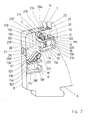
- Each of the two terminal connections 10 and 10 ' is a so-called plug-in terminal connection.
- the reference numerals without apostrophe refer to the upper terminal terminal 10
- the reference numerals with apostrophe refer to the lower terminal terminal 10 '.
- the description of the terminal connections is exemplified by the example of the upper terminal terminal 10.
- the lower terminal terminal 10 ' is constructed substantially identical, and the elements described at the terminal terminal 10 carry at the terminal terminal 10' the same reference numerals, each extended with an apostrophe.
- the terminal connection 10 comprises a busbar 102 and a clamping spring 12.
- the terminal connection 10 rests on a projection formed in the interior of the housing 3, which is not shown here, and is represented by webs and pins, of which only one journal 106 is shown here by way of example , Fixed in position in a known manner in the terminal connection space 18.
- the busbar 102 comprises a connection end 112 and an adjoining discharge region 114. At the connection end 112, it has a window-like recess 116 with a support edge 118 and a clamping edge 120 opposite the support edge.
- the clamping edge 120 is located at the transition of the terminal end 112 in the discharge area 114 and is further away from the rear narrow side 8 as the support edge 118th
- the clamping spring 12 has a support leg 212, with which it is supported on the support edge 118 of the bus bar 102.
- the support can be made so that the support leg 212 at its free end a raised edge (not shown), with which it includes the supporting edge 118 for the purpose of supporting partially.
- a curved piece 214 and thereon a clamping leg 216 connects.
- the stripped conductor end 16 of a connection conductor 14 is inserted through the connection opening 23 and through an insertion channel 28a associated with the connection opening, from the side of the curve piece 214 into the window-like recess 116 introduced. It is thus clamped between the clamping leg 216 and acting as an abutment clamping edge 120.
- the free end of the clamping leg 216 passes through the window-like recess 116th
- the clamping leg 216 is longitudinally slotted along a slot 11, so that two independently clampable part springs 13a, 13b arise, with which two connection conductors can be clamped to the same clamping edge 120 independently.
- the two connection conductors are each plugged through their own connection opening 23, 25 and guided in separate insertion openings, so that the separation of the connection conductors takes place through the connection openings and the insertion openings.
- the busbar 102 has approximately a U-shaped in the basic form, wherein the terminal end 112 forms the first U-leg, and the discharge region 114 is formed by a transverse web 220 and the second U-leg 222. At the free end of the second U-leg 222 a Aufkantung 224 is attached. At this Aufkantung 224 further connection conductors can be attached, with which the terminal connection 10 is connected to other modules within the switching device housing. In particular, the connection conductors can be welded, brazed, screwed or riveted to this upstand.
- An illustrated design of the busbar has the advantage that the forces acting on the terminal connection 10 when inserting and releasing the connecting conductor are taken up by this as a closed system, and thus forces on other elements of the service switching device, such as the housing can be reduced.
- the busbar 102 can be produced cost-effectively and simply and in a wide variety of shapes, for example as a stamped and bent part in very large quantities.
- connection conductor presses the partial spring assigned to the connection opening from the clamping edge 120 so far away that the conductor end passes through the window-like recess 116 and is finally pressed by the opposing force of the part spring against the clamping edge 120. If a second connection conductor is inserted through the second connection opening, then it bends the partial connection opening associated with the partial spring, and is also pressed by the restoring force to the clamping edge 120. Mechanically, however, the two connection conductors do not influence each other.
- the engaging channel 219 may be divided into two by a central web, so that two separate partial engagement channels arise, each of which is associated with one of the two part springs and actuation only the part spring assigned to it allows. This variant is not shown in the figures.
- the procedure for removing one of the inserted and clamped conductor ends First, the part spring is bent back by means of the actuating tool through the engaging channel 219, so that the conductor ends are released and can be pulled out.
- FIG 2 is further an arrangement of two terminal connections 10,10 'in two terminal connection spaces 18,18' in a service switching device according to the invention shown.
- the second terminal connection space 18 'with the second terminal connection 10' is located in the vicinity of the rear narrow side 8. Its associated connection openings 27 and 26 are introduced in the rear narrow side 8.
- the two connection openings 27,26 associated insertion channels 28 ', 28a' extend obliquely to the rear narrow side 8 on the clamping leg 216 'of the clamping spring 12'. As a result, a guide of the connecting conductor is ensured obliquely to the rear narrow side 8.
- connection openings 27,26 This is advantageous for the accessibility of the connection openings 27,26 when an inventive installation switching device is mounted in a series with other installation switching devices on a standard profile support rail, for example in a distributor housing. Then, namely, the rear narrow side 8, for example, upwards, and it is advantageous if the connection conductors can be inserted at the connection openings 27, 26 at an acute angle obliquely to the rear narrow side 8.
- the second terminal terminal 10 ' is in the otherwise identical structure as the first terminal terminal 10 inserted in the housing so that the clamping leg 216' of the clamping spring 12 'to the insertion channels 28a', 28 'points. This results in an approximately mirror-image arrangement of the two terminal connections 10, 10 'in the housing.
- the terminal terminal 10 may be provided for the connection of one phase and the terminal terminal 10 'for the connection of the neutral conductor in a circuit breaker or an auxiliary switch with half module width.
- the engagement channel 219 'assigned to the second terminal connection 10' runs from the rear front side 5 approximately along the rear narrow side 8 toward the clamping spring 12 '. This has the advantage of having access for the operating tool for both terminal connections from the same side of the device.
- the second engagement channel 219 'could also be attached to the rear narrow side 8 in the vicinity of the two connection openings 27,26, and there from the engagement opening 218', for example, also obliquely inwardly on the clamping leg 216 'of the clamping spring 12' point.
- the engagement channel 219 'perpendicular to the rear narrow side 8 extends.
- the invention is of course not limited to the embodiment shown.
- more than two terminal connections can be arranged with spring clips according to the invention in an installation switching device according to the invention.
Landscapes
- Connections Arranged To Contact A Plurality Of Conductors (AREA)
Applications Claiming Priority (1)
| Application Number | Priority Date | Filing Date | Title |
|---|---|---|---|
| DE102006049773A DE102006049773B4 (de) | 2006-10-21 | 2006-10-21 | Modulares Installationsschaltgerät |
Publications (1)
| Publication Number | Publication Date |
|---|---|
| EP1914838A1 true EP1914838A1 (fr) | 2008-04-23 |
Family
ID=38947673
Family Applications (1)
| Application Number | Title | Priority Date | Filing Date |
|---|---|---|---|
| EP07018999A Withdrawn EP1914838A1 (fr) | 2006-10-21 | 2007-09-27 | Interrupteur d'installation modulaire |
Country Status (5)
| Country | Link |
|---|---|
| US (1) | US7674140B2 (fr) |
| EP (1) | EP1914838A1 (fr) |
| CN (1) | CN101183749B (fr) |
| CA (1) | CA2607348A1 (fr) |
| DE (1) | DE102006049773B4 (fr) |
Cited By (2)
| Publication number | Priority date | Publication date | Assignee | Title |
|---|---|---|---|---|
| FR2936376A1 (fr) * | 2008-09-22 | 2010-03-26 | Frederic Michel Yves Raymond | Dispositif permettant un raccordement multiple de fils electriques sur borne modulaire a connection rapide |
| WO2010118815A1 (fr) * | 2009-04-17 | 2010-10-21 | Abb Ag | Borne à enfichage à ressort |
Families Citing this family (22)
| Publication number | Priority date | Publication date | Assignee | Title |
|---|---|---|---|---|
| DE102007039709A1 (de) * | 2007-08-22 | 2009-02-26 | Abb Ag | Installationsschaltgerät mit einer Anschlussklemmenanordnung |
| KR101524312B1 (ko) * | 2008-11-28 | 2015-05-29 | 삼성전자주식회사 | 전자 기기용 접촉 단자 |
| DE102009050367A1 (de) * | 2009-10-22 | 2011-04-28 | Phoenix Contact Gmbh & Co. Kg | Federkraftanschlussklemme |
| DE202010018149U1 (de) * | 2010-03-01 | 2014-05-13 | Phoenix Contact Gmbh & Co. Kg | Anschlussklemmenanordnung |
| DE102010024809B4 (de) * | 2010-06-23 | 2013-07-18 | Wago Verwaltungsgesellschaft Mbh | Anschlussklemme |
| CN101950872A (zh) * | 2010-09-21 | 2011-01-19 | 鸿富锦精密工业(深圳)有限公司 | 插座电极定位夹 |
| US8206188B1 (en) * | 2010-12-28 | 2012-06-26 | Cheng Uei Precision Industry Co., Ltd. | Connector terminal |
| FR2986104B1 (fr) * | 2012-01-23 | 2015-06-05 | Legrand France | Appareil electrique au format modulaire |
| DE102013008874A1 (de) * | 2012-07-11 | 2014-01-16 | Abb Ag | Installationsschaltgerät mit Anschlussklemmen |
| FR3026238B1 (fr) * | 2014-09-23 | 2016-10-21 | Abb France | Partie de barre conductrice pour un appareil electrique |
| ITUB20150163A1 (it) * | 2015-02-10 | 2016-08-10 | 4 Box Srl | Dispositivo elettrico con morsetto e sede spellafili |
| DE202015105022U1 (de) * | 2015-09-22 | 2016-12-23 | Weidmüller Interface GmbH & Co. KG | Anschlussvorrichtung für Leiter |
| CN106816347B (zh) * | 2017-03-27 | 2018-10-12 | 浙江中亿豪科技有限公司 | 一种组合式的断路器 |
| DE102018127284A1 (de) * | 2018-10-31 | 2020-04-30 | Bals Elektrotechnik Gmbh & Co. Kg | Klemmfeder für eine schraubenlose Anschlussklemme |
| DE202019102309U1 (de) * | 2019-04-24 | 2020-07-29 | Conta-Clip Verbindungstechnik Gmbh | Transformatorklemme |
| CN110223860A (zh) * | 2019-04-24 | 2019-09-10 | 宁波耀华电气科技有限责任公司 | 新型免压接端头接线的辅助开关 |
| CN110211819A (zh) * | 2019-04-24 | 2019-09-06 | 宁波耀华电气科技有限责任公司 | 一种免压接端头接线的辅助开关 |
| DE202019103271U1 (de) * | 2019-06-11 | 2020-09-16 | Wago Verwaltungsgesellschaft Mbh | Leiteranschlussklemme, Sortiment aus wenigstens einem Basismodul und unterschiedlich ausgebildeten Leiteranschlussmodulen einer Leiteranschlussklemme und Leiteranschlussklemmenblock |
| USD951881S1 (en) * | 2020-02-05 | 2022-05-17 | Dehn Se | Surge protection device |
| DE102020119372B4 (de) * | 2020-07-22 | 2023-12-07 | WAGO Verwaltungsgesellschaft mit beschränkter Haftung | Leiteranschlussklemme |
| US20250183706A1 (en) * | 2022-03-01 | 2025-06-05 | Renewable Systems Innovations Inc. | Wireless automatic transfer switching |
| US20230297048A1 (en) * | 2022-03-16 | 2023-09-21 | Schneider Electric USA, Inc. | Electrical power systems and methods |
Citations (9)
| Publication number | Priority date | Publication date | Assignee | Title |
|---|---|---|---|---|
| US4729744A (en) | 1985-10-09 | 1988-03-08 | La Telemecanique Electrique | Device for assembling together modular blocks of electric equipment |
| DE3805158A1 (de) | 1988-02-15 | 1989-08-24 | Wago Verwaltungs Gmbh | Reihenklemme zur zweileiter-stromversorgung von elektrischen oder elektronischen bauelementen, insbesondere initiatoren |
| EP1022808A2 (fr) | 1999-01-22 | 2000-07-26 | Wago Verwaltungsgesellschaft mbH | Borne de raccordement |
| DE19934550A1 (de) | 1999-07-20 | 2001-02-08 | Hager Electro Gmbh | Anschlußklemme für elektrische Leiter |
| EP1124286A1 (fr) | 2000-02-10 | 2001-08-16 | Hager Electro S.A. | Bornier débrochable pour appareil électrique modulaire |
| EP1199774A1 (fr) | 2000-10-21 | 2002-04-24 | Gerd Conrad | Barette à borne notamment barette multiétagée |
| EP1432077A1 (fr) | 2002-12-20 | 2004-06-23 | Hager Electro S.A. | Appareil électrique du type modulaire à faces de raccordement inclinées |
| EP1434307A1 (fr) | 2002-12-23 | 2004-06-30 | Wago Verwaltungsgesellschaft mbH | Borne de connexion pour des conducteurs électriques |
| DE102004013757A1 (de) | 2004-03-20 | 2005-10-13 | Ria-Btr Produktions-Gmbh | Elektrischer Koppelbaustein |
Family Cites Families (9)
| Publication number | Priority date | Publication date | Assignee | Title |
|---|---|---|---|---|
| DE19641206C2 (de) * | 1996-09-25 | 1999-12-23 | Wago Verwaltungs Gmbh | Anschlußklemme für elektrische Leiter |
| DE19753076C1 (de) * | 1997-11-29 | 1999-08-19 | Lumberg Karl Gmbh & Co | Elektrische Anschlußklemme, insbesondere Anreihklemme |
| DE20315898U1 (de) * | 2003-10-16 | 2005-02-24 | Weidmüller Interface GmbH & Co. KG | Anschlußklemme zum Aufsetzen auf ein Trägerelement |
| DE102004008447A1 (de) * | 2004-02-19 | 2005-09-08 | Abb Patent Gmbh | Federkraftklemme |
| FR2875944B1 (fr) * | 2004-09-27 | 2006-12-15 | Legrand Sa | Appareil comportant un bloc de raccordement |
| DE102005045596B3 (de) * | 2005-09-23 | 2007-06-21 | Siemens Ag | Feder-Steckklemme |
| DE202006009460U1 (de) * | 2005-10-29 | 2007-03-15 | Weidmüller Interface GmbH & Co. KG | Anschlussvorrichtung für Leiter |
| DE202006015363U1 (de) * | 2006-10-05 | 2008-02-21 | Wieland Electric Gmbh | Federkraftklemmstelle |
| US7510448B2 (en) * | 2006-10-06 | 2009-03-31 | Abb Patent Gmbh | Clamping connection, connecting terminal arrangement and installation switching device |
-
2006
- 2006-10-21 DE DE102006049773A patent/DE102006049773B4/de not_active Expired - Fee Related
-
2007
- 2007-09-27 EP EP07018999A patent/EP1914838A1/fr not_active Withdrawn
- 2007-10-17 US US11/873,432 patent/US7674140B2/en not_active Expired - Fee Related
- 2007-10-19 CA CA002607348A patent/CA2607348A1/fr not_active Abandoned
- 2007-10-19 CN CN2007101632511A patent/CN101183749B/zh not_active Expired - Fee Related
Patent Citations (9)
| Publication number | Priority date | Publication date | Assignee | Title |
|---|---|---|---|---|
| US4729744A (en) | 1985-10-09 | 1988-03-08 | La Telemecanique Electrique | Device for assembling together modular blocks of electric equipment |
| DE3805158A1 (de) | 1988-02-15 | 1989-08-24 | Wago Verwaltungs Gmbh | Reihenklemme zur zweileiter-stromversorgung von elektrischen oder elektronischen bauelementen, insbesondere initiatoren |
| EP1022808A2 (fr) | 1999-01-22 | 2000-07-26 | Wago Verwaltungsgesellschaft mbH | Borne de raccordement |
| DE19934550A1 (de) | 1999-07-20 | 2001-02-08 | Hager Electro Gmbh | Anschlußklemme für elektrische Leiter |
| EP1124286A1 (fr) | 2000-02-10 | 2001-08-16 | Hager Electro S.A. | Bornier débrochable pour appareil électrique modulaire |
| EP1199774A1 (fr) | 2000-10-21 | 2002-04-24 | Gerd Conrad | Barette à borne notamment barette multiétagée |
| EP1432077A1 (fr) | 2002-12-20 | 2004-06-23 | Hager Electro S.A. | Appareil électrique du type modulaire à faces de raccordement inclinées |
| EP1434307A1 (fr) | 2002-12-23 | 2004-06-30 | Wago Verwaltungsgesellschaft mbH | Borne de connexion pour des conducteurs électriques |
| DE102004013757A1 (de) | 2004-03-20 | 2005-10-13 | Ria-Btr Produktions-Gmbh | Elektrischer Koppelbaustein |
Cited By (2)
| Publication number | Priority date | Publication date | Assignee | Title |
|---|---|---|---|---|
| FR2936376A1 (fr) * | 2008-09-22 | 2010-03-26 | Frederic Michel Yves Raymond | Dispositif permettant un raccordement multiple de fils electriques sur borne modulaire a connection rapide |
| WO2010118815A1 (fr) * | 2009-04-17 | 2010-10-21 | Abb Ag | Borne à enfichage à ressort |
Also Published As
| Publication number | Publication date |
|---|---|
| CN101183749A (zh) | 2008-05-21 |
| US7674140B2 (en) | 2010-03-09 |
| DE102006049773B4 (de) | 2009-01-08 |
| US20080096441A1 (en) | 2008-04-24 |
| CA2607348A1 (fr) | 2008-04-21 |
| CN101183749B (zh) | 2011-05-25 |
| DE102006049773A1 (de) | 2008-04-30 |
Similar Documents
| Publication | Publication Date | Title |
|---|---|---|
| DE102006049773B4 (de) | Modulares Installationsschaltgerät | |
| DE102006047254B3 (de) | Installationsschaltgerät | |
| EP2143122B1 (fr) | Appareil de commutation d'installation | |
| EP1914839B1 (fr) | Commutateur d'installation | |
| EP1253670B1 (fr) | Borne à ressort et barette à bornes | |
| EP2319127B1 (fr) | Composant de connexion | |
| DE102008017245A1 (de) | Steckadapter für ein elektrisches Schaltgerät | |
| EP1818964B1 (fr) | Barrette de fusibles avec contacts de sortie latéraux et module adaptateur latéral | |
| EP3275049B2 (fr) | Ensemble de serrage, borne à ressort et interrupteur comprenant cet ensemble de serrage | |
| DE102011101238A1 (de) | Installationsschaltgerät | |
| EP1856709B1 (fr) | Commutateur electromecanique | |
| DE10152347C1 (de) | Schaltgerät mit adaptiertem mehrphasigem Sammelschienensystem | |
| EP0133152A1 (fr) | Dispositif pour la connexion de conducteurs auxiliaires à un appareil de commutation ou une combinaison d'appareils de commutation | |
| EP2608322A1 (fr) | Borne d'alimentation conductrice | |
| DE102020128775B4 (de) | Leiteranschlussklemme in Form eines Verteilerklemmenblocks | |
| DE102010040322A1 (de) | Schiebevorrichtung zur Befestigung eines Gehäuses | |
| DE102006047255A1 (de) | Klemmanschluss und Anschlussklemmenanordnung | |
| DE102006049772B4 (de) | Installationsschaltgerät | |
| DE69420923T2 (de) | Differentialschutzblock mit Kabeldurchgang | |
| EP1331693B1 (fr) | Plaque à bornes | |
| DE102011001152B4 (de) | Kontaktelement und Kontaktelementbaueinheit | |
| DE8618540U1 (de) | Mehrfach-Steckverbindungseinheit | |
| DE29916001U1 (de) | Installationsschalter | |
| EP1816707B1 (fr) | Plaque à bornes pour des appareils notamment pour des fiches | |
| DE69210636T2 (de) | Elektrische Schalttafel |
Legal Events
| Date | Code | Title | Description |
|---|---|---|---|
| PUAI | Public reference made under article 153(3) epc to a published international application that has entered the european phase |
Free format text: ORIGINAL CODE: 0009012 |
|
| AK | Designated contracting states |
Kind code of ref document: A1 Designated state(s): AT BE BG CH CY CZ DE DK EE ES FI FR GB GR HU IE IS IT LI LT LU LV MC MT NL PL PT RO SE SI SK TR |
|
| AX | Request for extension of the european patent |
Extension state: AL BA HR MK RS |
|
| 17P | Request for examination filed |
Effective date: 20081006 |
|
| 17Q | First examination report despatched |
Effective date: 20081117 |
|
| AKX | Designation fees paid |
Designated state(s): AT BE BG CH CY CZ DE DK EE ES FI FR GB GR HU IE IS IT LI LT LU LV MC MT NL PL PT RO SE SI SK TR |
|
| RAP1 | Party data changed (applicant data changed or rights of an application transferred) |
Owner name: ABB AG |
|
| STAA | Information on the status of an ep patent application or granted ep patent |
Free format text: STATUS: THE APPLICATION IS DEEMED TO BE WITHDRAWN |
|
| 18D | Application deemed to be withdrawn |
Effective date: 20151215 |