EP1914848A1 - Connecteur LED pour automobiles - Google Patents
Connecteur LED pour automobiles Download PDFInfo
- Publication number
- EP1914848A1 EP1914848A1 EP06122684A EP06122684A EP1914848A1 EP 1914848 A1 EP1914848 A1 EP 1914848A1 EP 06122684 A EP06122684 A EP 06122684A EP 06122684 A EP06122684 A EP 06122684A EP 1914848 A1 EP1914848 A1 EP 1914848A1
- Authority
- EP
- European Patent Office
- Prior art keywords
- open end
- outer case
- insertion section
- light emitting
- signal wire
- Prior art date
- Legal status (The legal status is an assumption and is not a legal conclusion. Google has not performed a legal analysis and makes no representation as to the accuracy of the status listed.)
- Pending
Links
- 238000003780 insertion Methods 0.000 claims description 25
- 230000037431 insertion Effects 0.000 claims description 25
- 230000005611 electricity Effects 0.000 description 8
- 238000012423 maintenance Methods 0.000 description 4
- 239000000945 filler Substances 0.000 description 2
- 238000000034 method Methods 0.000 description 2
Images


Classifications
-
- H—ELECTRICITY
- H01—ELECTRIC ELEMENTS
- H01R—ELECTRICALLY-CONDUCTIVE CONNECTIONS; STRUCTURAL ASSOCIATIONS OF A PLURALITY OF MUTUALLY-INSULATED ELECTRICAL CONNECTING ELEMENTS; COUPLING DEVICES; CURRENT COLLECTORS
- H01R33/00—Coupling devices specially adapted for supporting apparatus and having one part acting as a holder providing support and electrical connection via a counterpart which is structurally associated with the apparatus, e.g. lamp holders; Separate parts thereof
- H01R33/05—Two-pole devices
- H01R33/06—Two-pole devices with two current-carrying pins, blades or analogous contacts, having their axes parallel to each other
- H01R33/09—Two-pole devices with two current-carrying pins, blades or analogous contacts, having their axes parallel to each other for baseless lamp bulb
-
- H—ELECTRICITY
- H01—ELECTRIC ELEMENTS
- H01R—ELECTRICALLY-CONDUCTIVE CONNECTIONS; STRUCTURAL ASSOCIATIONS OF A PLURALITY OF MUTUALLY-INSULATED ELECTRICAL CONNECTING ELEMENTS; COUPLING DEVICES; CURRENT COLLECTORS
- H01R2201/00—Connectors or connections adapted for particular applications
- H01R2201/26—Connectors or connections adapted for particular applications for vehicles
Definitions
- the present invention relates to a vehicular light emitting diode connector, and more particularly to a connector having an outer case provided with grasp sections and an inner case provided with protuberances.
- the inner case is inserted and secured in a compartment of the outer case for connection of light emitting diodes and a vehicular light.
- each light emitting diode has a unique design and is not compatible with a traditional vehicular light.
- a vehicular light emitting diode connector comprising:
- said outer case comprises at least one insertion section thereof.
- said insertion section of said outer case comprises ribs thereof.
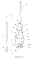
- a first embodiment of the present invention comprises an outer case 1, an inner case 2, a first signal wire 3, and a second signal wire 4.
- the outer case 1 comprises an open end 11, an insertion section 12, and a compartment 13.
- the insertion section 12 is disposed with a pair of corresponding ribs 121 therein.
- the compartment 13 interconnects with the open end 11 and the insertion section 12.
- a pair of slots 14 is longitudinally formed along the circumference of the outer case 1 with a pair of grasp sections 15 extending from the slots 14 outwardly.
- the inner case 2 is inserted into the compartment 13 of the outer case 1 through the open end 11.
- the inner case 2 comprises a through hole 21 therein to form a first open end 22 at one end and a second open end 23 at the other end.
- the outer wall of the second open end 23 is formed with a pair of protuberances 24.
- the protuberances 24 are in an equal height and correspond to each other to function as locating elements for the inner case 2 in the outer case 1.
- the first signal wire 3 is a negative electricity source, and is connected and secured to the inner wall of the first open end 22.
- the second signal wire 4 comprises a contact point 41 at one end, and is a positive electricity source.
- the contact point 41 of the second signal wire 4 is connected to the insertion section 12.
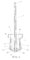
- the inner case 2 is inserted into the outer case 1 through the open end 11.
- the two protuberances 24 at the second open end 23 slide along the two slots 14 to facilitate sliding process and to maintain a secure status.
- the second open end 23 of the inner case 2 is located on the insertion section 12 of the outer case 1.
- the first signal wire 3 is secured to the inner wall of the first open end 22 to transmit negative electricity to the inner case 2.
- the second signal wire 4 is inserted into the outer case 1 through the insertion section 12 into the first open end 22 with the contact point 41 engaging with the insertion section 12 of the outer case 1 to transmit positive electricity.
- the outer case 1 is later filled with filler A to isolate the second signal wire 4 from the first signal wire 3 and to protect the two signal wires from tangling.
- This design is applicable to connect a light emitting diode and a traditional lighting system.
- the grasp sections 15 are formed to have an included angle that is easy for the user to hold the connector firmly and to facilitate maintenance.
- Figure 3 shows a second embodiment of the present invention, which comprises an outer case 1A, an inner case 2A, a first signal wire 3A and second signal wires 4A.
- the outer case 1A comprises an open end 11A, a number of insertion sections 12A, and a compartment 13A.
- Each insertion section 12A is disposed with a pair of corresponding ribs 121A therein.
- the compartment 13A interconnects with the open end 11A and the insertion sections 12A.
- a pair of slots 14A is longitudinally formed along the circumference of the outer case 1 with a pair of grasp sections 15A extending from the slots 14 outwardly.
- the inner case 2A is inserted into the compartment 13A of the outer case 1A through the open end 11A, and comprises a through hole 21 A therein to form a first open end 22A at one end and a second open end 23A at the other end.
- the outer wall of the second open end 23A is formed with a pair of protuberances 24A and 25A.
- the protuberances 24A and 25A are in an unequal height and correspond to each other to function as locating elements for the inner case 2A in the outer case 1A.
- the first signal wire 3A is a negative electricity source, and is connected and secured to the inner wall of the first open end 22A.
- Each of the second signal wires 4A comprises a contact point 41A at one end, and is a positive electricity source.
- the contact point 41A of each second signal wire 4A is connected to a relative insertion section 12A.
- the inner case 2A is inserted into the outer case 1A through the open end 11A.
- the two protuberances 24A and 25A slide along the two slots 14A to facilitate sliding process and to maintain a secure and steady status.
- the first signal wire 3A is secured to the inner wall of the first open end 22A to transmit negative electricity to the inner case 2A.
- Each of the second signal wires 4A is inserted into the outer case 1A through the insertion section 12A into the first open end 22A with the contact point 41A engaging with the insertion section 12A of the outer case 1A to transmit positive electricity.
- the outer case 1A is later filled with filler A to isolate the second signal wire 4A from the first signal wire 3A and to protect the signal wires from tangling.
- This design is applicable to connect light emitting diodes a nd a traditional lighting system.
- the grasp sections 15A are formed to have an included angle that is easy for the user to hold the connector firmly and to facilitate maintenance.
Landscapes
- Details Of Connecting Devices For Male And Female Coupling (AREA)
Priority Applications (1)
| Application Number | Priority Date | Filing Date | Title |
|---|---|---|---|
| EP06122684A EP1914848A1 (fr) | 2006-10-20 | 2006-10-20 | Connecteur LED pour automobiles |
Applications Claiming Priority (1)
| Application Number | Priority Date | Filing Date | Title |
|---|---|---|---|
| EP06122684A EP1914848A1 (fr) | 2006-10-20 | 2006-10-20 | Connecteur LED pour automobiles |
Publications (1)
| Publication Number | Publication Date |
|---|---|
| EP1914848A1 true EP1914848A1 (fr) | 2008-04-23 |
Family
ID=37836885
Family Applications (1)
| Application Number | Title | Priority Date | Filing Date |
|---|---|---|---|
| EP06122684A Pending EP1914848A1 (fr) | 2006-10-20 | 2006-10-20 | Connecteur LED pour automobiles |
Country Status (1)
| Country | Link |
|---|---|
| EP (1) | EP1914848A1 (fr) |
Citations (6)
| Publication number | Priority date | Publication date | Assignee | Title |
|---|---|---|---|---|
| FR2560427A1 (fr) * | 1984-02-29 | 1985-08-30 | Maville Paris Creations | Douilles electriques pour branchement de petites lampes electriques |
| US4970632A (en) * | 1990-03-16 | 1990-11-13 | Tseng Jeow N | Socket and bulb snap fastener for Christmas light strings |
| DE4109678C1 (fr) * | 1991-03-23 | 1992-05-27 | Broekelmann, Jaeger & Busse Gmbh & Co, 5760 Arnsberg, De | |
| DE9205179U1 (de) * | 1991-06-28 | 1992-06-25 | Chuang, Wen-Te, Hsin Chu | Fassung und Fassungsanschluß für Glühbirnen |
| US5701051A (en) * | 1996-02-15 | 1997-12-23 | Lin; Blake | Miniature lamp |
| US6217191B1 (en) * | 1998-05-29 | 2001-04-17 | Jeng-Shyong Wu | Multiple lamp socket device |
-
2006
- 2006-10-20 EP EP06122684A patent/EP1914848A1/fr active Pending
Patent Citations (6)
| Publication number | Priority date | Publication date | Assignee | Title |
|---|---|---|---|---|
| FR2560427A1 (fr) * | 1984-02-29 | 1985-08-30 | Maville Paris Creations | Douilles electriques pour branchement de petites lampes electriques |
| US4970632A (en) * | 1990-03-16 | 1990-11-13 | Tseng Jeow N | Socket and bulb snap fastener for Christmas light strings |
| DE4109678C1 (fr) * | 1991-03-23 | 1992-05-27 | Broekelmann, Jaeger & Busse Gmbh & Co, 5760 Arnsberg, De | |
| DE9205179U1 (de) * | 1991-06-28 | 1992-06-25 | Chuang, Wen-Te, Hsin Chu | Fassung und Fassungsanschluß für Glühbirnen |
| US5701051A (en) * | 1996-02-15 | 1997-12-23 | Lin; Blake | Miniature lamp |
| US6217191B1 (en) * | 1998-05-29 | 2001-04-17 | Jeng-Shyong Wu | Multiple lamp socket device |
Similar Documents
| Publication | Publication Date | Title |
|---|---|---|
| CA2623604C (fr) | Douille pour guirlande lumineuse | |
| US8092255B2 (en) | Bulb set structure | |
| US8575826B1 (en) | Connection structure of LED lamp holder and heat radiation fins | |
| US8540414B2 (en) | Detachable LED bulb | |
| EP4622392A3 (fr) | Système d'éclairage à del en réseau | |
| US20120175653A1 (en) | Led connector assembly | |
| WO2009085529A3 (fr) | Appareil d'éclairage à del pourvu d'un raccord pivotant | |
| EP2287521A3 (fr) | Dispositif d'éclairage | |
| WO2012009260A3 (fr) | Support de carte de circuit imprimé pour un tube de lampe à diodes électroluminescentes | |
| US20140273568A1 (en) | Bulb socket having terminals connected to a partially stripped cord | |
| US9083123B2 (en) | Visually evident connection system for plug-in power/data cable | |
| WO2008039454A3 (fr) | Connecteur de sécurité à ergots radiaux, à verrouillage par torsion, sous charge ressort et sans à-coup pour lampe | |
| KR20120024769A (ko) | 조명관용 엔드캡 조립체 | |
| US7527531B2 (en) | Vehicular light emitting diode connector | |
| US10145520B1 (en) | Light assembly | |
| US7140920B1 (en) | Electric plug | |
| EP1914848A1 (fr) | Connecteur LED pour automobiles | |
| US8777464B2 (en) | Rotatable illumination device | |
| EP2484967A2 (fr) | Unité d'éclairage | |
| CN204333837U (zh) | 接线盒 | |
| US7568951B1 (en) | Socket for fairy light | |
| EP2581643A1 (fr) | Dispositif d'éclairage, en particulier un dispositif d'éclairage à DEL | |
| KR101218333B1 (ko) | 이종 플러그 조립형 엘이디 조명등 | |
| US11873950B2 (en) | Light source and light fitting | |
| JP2010129325A (ja) | Led照明灯のコネクタ |
Legal Events
| Date | Code | Title | Description |
|---|---|---|---|
| PUAI | Public reference made under article 153(3) epc to a published international application that has entered the european phase |
Free format text: ORIGINAL CODE: 0009012 |
|
| 17P | Request for examination filed |
Effective date: 20070817 |
|
| AK | Designated contracting states |
Kind code of ref document: A1 Designated state(s): AT BE BG CH CY CZ DE DK EE ES FI FR GB GR HU IE IS IT LI LT LU LV MC NL PL PT RO SE SI SK TR |
|
| AX | Request for extension of the european patent |
Extension state: AL BA HR MK RS |
|
| AKX | Designation fees paid |
Designated state(s): AT BE BG CH CY CZ DE DK EE ES FI FR GB GR HU IE IS IT LI LT LU LV MC NL PL PT RO SE SI SK TR |
|
| GRAP | Despatch of communication of intention to grant a patent |
Free format text: ORIGINAL CODE: EPIDOSNIGR1 |
|
| STAA | Information on the status of an ep patent application or granted ep patent |
Free format text: STATUS: GRANT OF PATENT IS INTENDED |