EP1914896A1 - Appareil de transmission, appareil de codage et appareil de décodage - Google Patents
Appareil de transmission, appareil de codage et appareil de décodage Download PDFInfo
- Publication number
- EP1914896A1 EP1914896A1 EP05780226A EP05780226A EP1914896A1 EP 1914896 A1 EP1914896 A1 EP 1914896A1 EP 05780226 A EP05780226 A EP 05780226A EP 05780226 A EP05780226 A EP 05780226A EP 1914896 A1 EP1914896 A1 EP 1914896A1
- Authority
- EP
- European Patent Office
- Prior art keywords
- bits
- dummy
- code
- systematic
- encoding
- Prior art date
- Legal status (The legal status is an assumption and is not a legal conclusion. Google has not performed a legal analysis and makes no representation as to the accuracy of the status listed.)
- Granted
Links
Images









Classifications
-
- H—ELECTRICITY
- H03—ELECTRONIC CIRCUITRY
- H03M—CODING; DECODING; CODE CONVERSION IN GENERAL
- H03M13/00—Coding, decoding or code conversion, for error detection or error correction; Coding theory basic assumptions; Coding bounds; Error probability evaluation methods; Channel models; Simulation or testing of codes
- H03M13/29—Coding, decoding or code conversion, for error detection or error correction; Coding theory basic assumptions; Coding bounds; Error probability evaluation methods; Channel models; Simulation or testing of codes combining two or more codes or code structures, e.g. product codes, generalised product codes, concatenated codes, inner and outer codes
- H03M13/2957—Turbo codes and decoding
-
- H—ELECTRICITY
- H03—ELECTRONIC CIRCUITRY
- H03M—CODING; DECODING; CODE CONVERSION IN GENERAL
- H03M13/00—Coding, decoding or code conversion, for error detection or error correction; Coding theory basic assumptions; Coding bounds; Error probability evaluation methods; Channel models; Simulation or testing of codes
- H03M13/63—Joint error correction and other techniques
- H03M13/635—Error control coding in combination with rate matching
-
- H—ELECTRICITY
- H03—ELECTRONIC CIRCUITRY
- H03M—CODING; DECODING; CODE CONVERSION IN GENERAL
- H03M13/00—Coding, decoding or code conversion, for error detection or error correction; Coding theory basic assumptions; Coding bounds; Error probability evaluation methods; Channel models; Simulation or testing of codes
- H03M13/63—Joint error correction and other techniques
- H03M13/635—Error control coding in combination with rate matching
- H03M13/6356—Error control coding in combination with rate matching by repetition or insertion of dummy data, i.e. rate reduction
-
- H—ELECTRICITY
- H04—ELECTRIC COMMUNICATION TECHNIQUE
- H04L—TRANSMISSION OF DIGITAL INFORMATION, e.g. TELEGRAPHIC COMMUNICATION
- H04L1/00—Arrangements for detecting or preventing errors in the information received
- H04L1/004—Arrangements for detecting or preventing errors in the information received by using forward error control
- H04L1/0041—Arrangements at the transmitter end
-
- H—ELECTRICITY
- H04—ELECTRIC COMMUNICATION TECHNIQUE
- H04L—TRANSMISSION OF DIGITAL INFORMATION, e.g. TELEGRAPHIC COMMUNICATION
- H04L1/00—Arrangements for detecting or preventing errors in the information received
- H04L1/004—Arrangements for detecting or preventing errors in the information received by using forward error control
- H04L1/0045—Arrangements at the receiver end
- H04L1/0047—Decoding adapted to other signal detection operation
- H04L1/005—Iterative decoding, including iteration between signal detection and decoding operation
-
- H—ELECTRICITY
- H04—ELECTRIC COMMUNICATION TECHNIQUE
- H04L—TRANSMISSION OF DIGITAL INFORMATION, e.g. TELEGRAPHIC COMMUNICATION
- H04L1/00—Arrangements for detecting or preventing errors in the information received
- H04L1/004—Arrangements for detecting or preventing errors in the information received by using forward error control
- H04L1/0056—Systems characterized by the type of code used
- H04L1/0064—Concatenated codes
- H04L1/0066—Parallel concatenated codes
-
- H—ELECTRICITY
- H04—ELECTRIC COMMUNICATION TECHNIQUE
- H04L—TRANSMISSION OF DIGITAL INFORMATION, e.g. TELEGRAPHIC COMMUNICATION
- H04L1/00—Arrangements for detecting or preventing errors in the information received
- H04L1/004—Arrangements for detecting or preventing errors in the information received by using forward error control
- H04L1/0056—Systems characterized by the type of code used
- H04L1/0067—Rate matching
-
- H—ELECTRICITY
- H03—ELECTRONIC CIRCUITRY
- H03M—CODING; DECODING; CODE CONVERSION IN GENERAL
- H03M13/00—Coding, decoding or code conversion, for error detection or error correction; Coding theory basic assumptions; Coding bounds; Error probability evaluation methods; Channel models; Simulation or testing of codes
- H03M13/63—Joint error correction and other techniques
- H03M13/6306—Error control coding in combination with Automatic Repeat reQuest [ARQ] and diversity transmission, e.g. coding schemes for the multiple transmission of the same information or the transmission of incremental redundancy
-
- H—ELECTRICITY
- H04—ELECTRIC COMMUNICATION TECHNIQUE
- H04L—TRANSMISSION OF DIGITAL INFORMATION, e.g. TELEGRAPHIC COMMUNICATION
- H04L1/00—Arrangements for detecting or preventing errors in the information received
- H04L1/12—Arrangements for detecting or preventing errors in the information received by using return channel
- H04L1/16—Arrangements for detecting or preventing errors in the information received by using return channel in which the return channel carries supervisory signals, e.g. repetition request signals
- H04L1/18—Automatic repetition systems, e.g. Van Duuren systems
- H04L1/1812—Hybrid protocols; Hybrid automatic repeat request [HARQ]
Definitions
- the present invention relates to a transmission device, encoding device, and decoding device, and in particular relates to a transmission device, encoding device, and decoding device in a communication system in which dummy bits are added to information and encoding is subjected to the information to which the dummy bits are added, then the dummy bits are deleted from the results of the encoding to generate a systematic code and the systematic code is transmitted, and on the receiving side maximum-likelihood values for dummy bits are inserted and decoding is performed.
- Turbocodes are one example of systematic codes.
- an information alphabet is considered.
- Fig. 36 shows the configuration of a communication system in which block encoding is performed in the transmitter and decoding is performed in the receiver;
- the transmitter 1 comprises an encoding portion 1a, which encodes information u of K bits to generate an N-bit block code x, and a modulation portion 1b which modulates and transmits the block code.
- the receiver 2 comprises a demodulation portion 2a, which demodulates the signal received via a transmission path 3, and a decoding portion 2b, which decodes the N bits of received information to obtain the original K bits of transmitted information.
- a turbocode can be adopted as the code of the encoding portion 1a.
- the decoding portion 2b comprises a decoder 2c, which performs error detection and correction processing of the received likelihood data y and performs decoding to restore the original transmitted K bits of information and outputs estimation information.
- the block code x transmitted from the transmitter 1 is affected by the transmission path 3, and so is not input to the decoder 2c in the form transmitted, but is input to the decoder 2c as likelihood data.
- the likelihood data comprises reliabilities as to whether a code bit is 0 or 1, and signs (indicating "0" if +1 and "1" if -1).
- the decoder 2c performs stipulated decoding processing based on the likelihood data for each signed bit, to estimate the information bits u. In the case of a turbocode, the decoder 2c performs maximum a posteriori probability (MAP) decoding.
- MAP maximum a posteriori probability
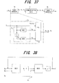
- Fig. 37 shows the configuration of a turbo encoding portion 1a; Fig. 38 shows the configuration of a turbo decoding portion 2b.
- a turbo encoding portioin is a systematic encoder comprising a number of element encoders and an interleaver; by adopting MAP decoding, decoding result errors can be reduced by increasing the number of decoding repetitions.
- Fig. 37 is one such example; in this encoder, two element encoders are arranged in parallel with one interleaver therebetween.
- u [u0, u1, u2, u3, ..., U K-1 ] is the information data for transmission, of length K; xa, xb, xc are encoded data resulting from encoding of the information data u by the turbo encoder 1a; ya, yb, yc are received signals, resulting from propagation of the encoded data xa, xb, xc over the communication path 3, and are affected by noise and fading; and u' is the result of decoding of the received data ya, yb, yc by the turbo decoder 2b.
- the encoded data xa is the information data u itself; the encoded data xb is data resulting from convolution encoding of the information data u by a first element encoder ENC1; and the encoded data xc is data resulting from interleaving ( ⁇ ) of the information data u and convolution encoding by a second element encoder ENC2. That is, the turbo encoder performs systematic encoding using two convolutions; xa is the information data, and xb and xc are parity data.
- the P/S conversion portion 1d converts the encoded data xa, xb, xc into a series and outputs the result.
- the first element decoder DEC1 performs decoding using ya and yb among the received signals ya, yb, yc.
- the first element decoder DEC1 is a soft decision-output element decoder, which outputs likelihoods of decoding results.
- the second element decoder DEC2 similarly performs decoding using yc and the likelihoods output from the first element decoder DEC1.
- the second element decoder DEC2 is also a soft decision-output element decoder, which outputs likelihoods of decoding results.
- yc is the received signal corresponding to xc, which results from interleaving and encoding the original data u; hence likelihoods output from the first element decoder DEC1 are interleaved ( ⁇ ) before input to the second element decoder DEC2. Likelihoods output from the second element decoder DEC2 are deinterleaved ( ⁇ -1 ), and are then input to the first element decoder DEC1 as feedback. The "0" and "1" hard decision results of the deinterleaving results of the second element decoder DEC2 are taken to be the turbo decoding results (decoded data) u'.
- MAP element decoders can be used as the first and second element decoders DEC1, DEC2 in the turbo decoder.
- a 3GPP W-CDMA mobile communication system may be considered as a concrte form of the communication system of Fig. 36 .
- Fig. 39 shows the configuration of a 3GPP W-CDMA mobile communication system; the wireless base stations are transmitters of Fig. 36 , and the mobile station is a receiver.
- the mobile communication system comprises a core network 11, wireless base station control devices (RNC, radio network controllers) 12, 13, demultiplexing devices 14, 15, wireless base stations (Node B) 16 1 to 16 5 , and a mobile station (UE, user equipment) 17.
- the core network 11 is a network which performs routing within the mobile communication system, and can for example be configured as an ATM switching network, packet-switched network, router network, or similar.
- the core network 11 is also connected to other public networks (PSTN), and the mobile station 7 can also communicate with fixed telephone sets and similar.
- the wireless base station control devices (RNCs) 12, 13 are positioned as higher-level devices relative to the wireless base stations 16 1 to 16 5 , and are provided with functions for controlling these wireless base stations 16 1 to 16 5 (ex. Function for managing wireless resources used, and similar).
- the demultiplexing devices 14, 15 are provided between the RNCs and the wireless base stations, and separate signals addressed to each of the wireless base stations received from the RNCs 12, 13, for output to the respective wireless base stations, as well as executing control to multiplex signals from the wireless base stations and pass the signals to the RNCs.
- Wireless resources of the wireless base stations 16 1 to 16 3 are managed by the RNC 12, and wireless resources of the wireless base stations 16 4 and 16 5 are managed by the RNC 13, while the base stations perform wireless communication with the mobile station 17.
- the mobile station 17 exists within the wireless area of the wireless base stations 16 i , a wireless connection with the wireless base stations 16 i is established, and communication with other communication devices is performed via the core network 11.
- HSDPA High Speed Downlink Packet Access
- HSDPA employs an adaptive encoding modulation method, and is characterized by the fact that the number of bits in the transport block TrBL, number of multiplex codes, and modulation method (QPSK modulation, 16QAM modulation) are switched adaptively according to the wireless environment between the wireless base station and the mobile station.
- QPSK modulation, 16QAM modulation QPSK modulation, 16QAM modulation
- HSDPA adopts an H-ARQ (Hybrid Automatic Repeat reQuest) method.
- H-ARQ when an error is detected by the mobile station in data received from a wireless base station, resending is requested (a NACK signal is sent) to the wireless base station. Upon receiving this resend request, the wireless base station resends the data, and so the mobile station uses both the data already received and the resent received data to perform error correction decoding. In this way, in H-ARQ previously received data is effectively utilized even when there are errors, so that the gain of error-correction decoding is increased, and consequently the number of resends can be kept small.
- an ACK signal is received from a mobile station, there is no longer a need for resending since data transmission has been successful, and so the next data is transmitted.
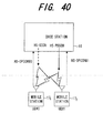
- the main wireless channels used in HSDPA are, as shown in Fig. 40 , (1) HS-SCCH (High Speed-Shared Control Channel), (2) HS-PDSCH (High Speed-Physical Downlink Shared Channel), and (3) HS-DPCCH (High Speed-Dedicated Physical Control Channel).
- HS-SCCH and HS-PDSCH are shared channels in the downlink direction, that is, from wireless base stations to mobile stations;
- HS-PDSCH is a shared channel which transmits packets in the downlink direction, while HS-SCCH is a control channel which transmits various parameters relating to data transmitted in HS-PDSCH.
- HS-SCCH is a channel used for notification of the transmission of data via HS-PDSCH; the various parameters are the destination mobile station information, transmission bitrate information, modulation method information, number of spreading codes allocated (number of codes), rate matching patterns for the transmission data, and other information.
- HS-DPCCH is a dedicated control channel in the uplink direction, that is, from mobile stations to wireless base stations, and is used when transmitting, from mobile stations to wireless base stations, the reception results (ACK signals, NACK signals) for data received via HS-PDSCH.
- HS-DPCCH is also used to transmit CQI (Channel Quality Indicator) values, based on the reception quality of signals received from wireless base stations, to wireless base stations.
- CQI Channel Quality Indicator
- the wireless base stations can judge the quality of downlink wireless environments, and if an environment is satisfactory, can switch to a modulation method enabling faster data transmission, but if the environment is poor, can switch to a modulation method for slower data transmission, and by this means can perform adaptive modulation.
- a base station has a CQI table which defines formats with different transmission speeds according to CQI values of 1 to 30; parameters (transmission rate, modulation method, number of multiplexing codes, and similar) are determined according to the CQI value by making a reference to the CQI table, and are notified mobile stations by HS-SCCH, while in addition data is transmitted to mobile stations using HS-PDSCH based on the parameters.
- the transmitter 1 and the receiver 2 in Fig. 36 are a wireless base station and a mobile station (mobile terminal) respectively.
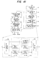
- Fig. 41 shows the data transmission processing block of a 3GPP W-CDMA wireless base station
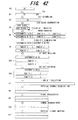
- Fig. 42 shows the data format used in explanation of transmission processing (see 3GPP, TS25.212v5.9.0).
- An example is shown for which the number of code blocks is 2, both 1stRM 25b and 2nsRM 25c in the physical layer H-ARQ function portion 25 are puncturing, and the number of physical channel codes is 2.
- the dummy bits are not limited to an all-"1"s pattern or to a repeated alternation of "1"s and "0"s, as in “1010 ... 10", and any prescribed pattern can be used.
- the decoding portion of the receiver inserts the dummy bits 200 deleted on the transmitting side into the demodulated systematic code 500 as maximum probabilities (reliability ⁇ ), and then performs turbo decoding and outputs information bits 100.
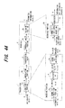
- Fig. 44 shows the configuration of a communication system which realizes the encoding/decoding method of Fig. 43 ; portions which are the same as in Fig. 36 are assigned the same symbols.
- the encoding portion 1a of the transmitter 1 applies forward error correction (FEC) to the information bits u, in order to perform transmission with high reliability, the modulation portion 1b modulates the resulting code bits x, and the modulated signals are transmitted to the receiver 2 via the wireless propagation path 3.
- the demodulation portion 2a of the receiver 2 demodulates the received data, and inputs to the decoding portion 2b likelihood data y comprising reliabilities as to whether code bits are "0" or "1" and symbols (+1 ⁇ 0, -1 ⁇ 1).
- the decoding portion 2b performs stipulated decoding processing based on the likelihood data for each code bit, and estimates the information bits u.
- the modulation portion 1b modulates the information bits x and transmits the result.
- the decoder 2e performs turbo decoding of the N1 likelihood data items (y, a), and outputs information bit estimation results.
- an object of this invention is to insert dummy bits into information bits so as to enable effective reduction of decoding errors.
- a further object of this invention is, in the case of a code, such as a turbocode, which performs interleaving and deinterleaving upon encoding, to insert dummy bits into information bit positions such that decoding errors can be effectively reduced, taking interleaving and deinterleaving into account.
- a further object of this invention is to enable accurate decoding even when dummy bits are inserted into information bits and encoding is performed.
- the first transmission device comprises a code rate monitoring portion, which monitors whether the code rate of the systematic code for transmission is a value within a specific range determined by decoding characteristic in a case where dummy bits are not inserted; a dummy bit insertion portion, which, when the code rate is a value within the specific range, inserts dummy bits into information bits and shifts the decoding characteristic, so that the code rate is a value outside a specific range determined by the decoding characteristic after shifting; a systematic code generation portion, which performs systematic encoding of information bits into which the dummy bits are inserted, and also deletes the dummy bits from the results of the systematic encoding to generate a systematic code; and, a rate matching portion, which performs rate matching processing such that the size of the systematic code from which the dummy bits are deleted is equal to a size determined by the transmission rate of
- the first transmission device By means of the first transmission device, dummy bits are added such that the code rate does not become a specific value which causes degradation of the decoding characteristic, so that decoding characteristic degradation can be prevented.
- the above objects are attained by means of a second transmission device, in a communication system in which information bits into which dummy bits are inserted are subjected to systematically encoding, the dummy bits are deleted from the results of the encoding to obtain a systematic code which is transmitted, and on the receiving side the dummy bits deleted on the transmitting side are inserted into the received systematic code and decoding is performed.
- the second transmission device comprises a dummy bit insertion portion, which inserts dummy bits into information bits; a systematic code generation portion, which performs turbo encoding of information bits into which the dummy bits are inserted, and also deletes the dummy bits from the results of the turbo encoding to generate a systematic code and a transmission portion, which transmits the systematic code wherein the dummy bit insertion portion inserts dummy bits into the information bits such that, in the information bits both before and after interleaving in the turbo encoding processing, the dummy bit insertion position patterns are substantially uniform.
- the second transmission device in a case where turbocode is adopted, the dummy bit insertion position patterns in both the first and second inputs, which are the inputs to the first element encoder and to the second element encoder, are made as uniform as possible, so that decoding characteristics can be improved.
- the above objects are attained by means of a third transmission device, in a communication system in which systematic code obtained by adding parity bits to information bits is transmitted, and on the receiving side the systematic code is decoded.
- the third transmission device comprises a dummy bit size decision portion, which decides the size of the dummy bits to be inserted into the information bits in encoding processing, a turbo encoding portion, which generates parity bits using the information bits into which the dummy bits are inserted, and moreover adds the parity bits to the information bits into which dummy bits are not inserted to generate a systematic code and outputs the systematic code and a transmission portion, which transmits the systematic code
- the turbo encoding portion comprises a dummy bit insertion portion, which inserts first dummy bits of a prescribed size into the information bits, and inserts second dummy bits of a prescribed size into the information bits resulting from interleaving; an element encoding portion, which performs first and second element encoding of the information bits into which the first and second dummy bits are inserted, to generate first and second parity bits; and a combination portion, which takes information bits into which the dummy bits are not inserted to be systematic bits, and combines the systematic bits
- a decoding device on the receiving side corresponding to the third transmission device comprises an element decoding portion, which performs first and second element decoding corresponding to the first and second element encoding; a dummy bit data deletion portion, which deletes the first and second dummy bits from the results of the first and second element decoding respectively; an interleaving portion, which performs interleaving of the first decoding result, obtained from the first element decoding result by deleting the first dummy bits; a deinterleaving portion, which performs deinterleaving of the second decoding result, obtained from the second element decoding result by deleting the second dummy bits; and, a dummy bit insertion portion, which inserts the first and second dummy bits, as maximum-likelihood values, into the first and second decoding results to which interleaving and deinterleaving are subjected respectively, and inputs the results to the element decoding portion.
- the third transmission device in a case where turbocode is adopted, dummy bit insertion positions in the first and second inputs of the first element encoder and second element encoder can be decided mutually independently, so that dummy bit insertion positions can easily be made uniform, and decoding characteristics can be improved. Further, by means of the third transmission device, since the dummy bits are deleted in the turbo encoder, a dummy bit deletion portion to delete dummy bits from systematic bits can be rendered unnecessary.
- Fig. 1 shows the configuration of the transmission processing portion 30 of the wireless base station of a first embodiment; portions which are the same as in the transmission processing portion of the prior art shown in Fig. 41 are assigned the same symbols.
- the transmission processing portion 30 transmits information such as packets to a mobile station by means of the HSDPA shared channel HS-PDSCH.
- the transmission processing portion 30 comprises a CRC addition portion 21; bit scrambling portion 22; code block segmentation portion 23; dummy bit insertion portion 31; channel coding portion (encoding portion) 24; physical layer HARQ function portion 25; physical channel segmentation portion 26; HS-PDSCH interleaving portion 27; constellation rearrangement portion 28; physical channel mapping portion 29; and transmission portion 32 which transmits information.
- the dummy bit insertion portion 31 is provided between the code block segmentation portion 23 and the encoding portion 24, and inserts dummy bits into information bits.
- the physical layer HARQ function portion 25 comprises a bit segmentation portion 25a, first rate matching portion 25b, second rate matching portion 25c, and bit collection portion 25d.
- the first rate matching portion 25b comprises, in addition to rate matching portions 25b-1, 25b-2 for parity 1 and 2, a dummy bit deletion portion 25b-3, which deletes dummy bits from the systematic bits; similarly to the prior art, the second rate matching portion 25c comprises rate matching processing portions 25c-1, 25c-2 for parity 1 and 2, and a systematic bit rate matching processing portion 25c-3.
- the dummy bit deletion portion 25b-3 deletes dummy bits which have been inserted into systematic bits by the dummy bit insertion portion 31.
- the first rate matching portion 25b passes systematic bits without performing any processing; but in the first embodiment, dummy bit deletion processing is performed by the dummy bit deletion portion 25b-3 simultaneously with puncturing of parity bits 1, 2 by the rate matching processing portions 25b-1 and 25b-2.
- Fig. 2 explains dummy bit insertion processing
- Fig. 3 explains dummy bit deletion processing.
- filler bits are inserted to adjust the size.
- Filler bits have value "0", and are inserted at the beginning of the original data.
- the dummy bit insertion portion 31 inserts dummy bits of size K0/2 into each code block ((b) in Fig. 2 ), the encoding portion 24 performs encoding, such as for example turbo encoding, of each code block with the dummy bits inserted ((c) of Fig. 2 ).
- the bit segmentation portion 25a of the physical layer HARQ function portion 25 divides the code of each of the code blocks output from the encoding portion 24 into (1) systematic bits + dummy bits, (2) parity bits 1, and (3) parity bits 2, and concatenates bits of the same type (see (a) in Fig. 3 ). Then, the first rate matching portion 25b of the physical layer HARQ function portion 25 checks to determine whether the total bit length of data set D5 is greater than the stipulated buffer size NIR, and if greater, performs puncturing of parity bits 1 and parity bits 2 so that the size is the same as NIR, and at the same time deletes the dummy bits from the systematic bits ((b) in Fig. 3 ).
- the second rate matching portion 25c of the HARQ function portion 25 performs rate matching (repetition or puncturing) of the data set D61 of systematic bits and parity bits 1, 2 shown in (b) of Fig. 3 , according to the specified H-ARQ transmission parameters. Thereafter, processing similar to that of the prior art is performed, and systematic code with the dummy bits deleted is transmitted. On the receiving side, the systematic code is received, then the dummy bits deleted on the transmitting side are inserted, as maximum-likelihood values, into the received systematic code, and thereafter turbo decoding is performed to obtain the information bits.
- the information necessary for reception (address, modulation method, dummy bit size, dummy bit insertion method, and similar) is transmitted to the reception device in advance as necessary through the shared channel HS-SCCH.
- the reception device the positions of dummy bit insertion on the transmitting side are known, and so maximum-likelihood dummy bits are inserted at these positions and decoding is performed.
- the dummy bit size calculation portion 23a calculates the size K0 of dummy bits based on the specified code rate R using the equation (2)
- the segmentation portion 23c segments the bit-scrambled data set D2 into the specified number of segments
- the dummy bit insertion portion 31 inserts K0/2 dummy bits into each code block
- the encoding portion 24 performs encoding of each of the code blocks with dummy bits inserted.
- the dummy bits are inserted into the information bits, then parity bits are added to the information bits into which the dummy bits are inserted by turbo encoding, thereafter the dummy bits are deleted from the turbo code to obtain systematic code which is transmitted; on the receiving side, the systematic code is received, then the dummy bits deleted on the transmitting side are added, as maximum-likelihood values, to the received systematic code, and thereafter turbo decoding is performed, so that decoding errors can be reduced.
- turbo decoding turbo decoding
- Fig. 5 shows the configuration of a turbo encoder 24; 24a is a first element encoder which encodes information bits into which dummy bits have been inserted, 24b is an interleaving portion which interleaves information bits into which dummy bits have been inserted, 24c is a second element encoder which encodes the interleaving result, 24d is a dummy bit deletion portion which deletes dummy bits, and 24e is a P/S conversion portion which converts the outputs of the element encoders 24a, 24b and the dummy bit deletion portion 24d into serial data.
- dummy bits are inserted such that the code rate is a fixed value to perform encoding, and the entire bit size of the transmission data is fixed at Ndata.
- Ndata is equal to the number of codes times the physical channel size.
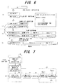
- Fig. 6 explains dummy bit processing in the wireless base station of the second embodiment; the configuration of the transmission processing portion is the same as that of the first embodiment in Fig. 1 .
- the code block segmentation portion 23 performs code block segmentation of the data set D2 which has been subjected to bit-scrambling.
- the dummy bit insertion portion 31 inserts K0/2 dummy bits into each code block ((b) in Fig. 6 ), and the encoding portion 24 performs encoding of each code block with dummy bits inserted, by for example performing turbo encoding ((c) in Fig. 6 ).
- the first rate matching portion 25b of the physical layer HARQ function portion 25 checks whether the code bit length is greater than the stipulated buffer size NIR, and if greater, performs puncturing of parity bits 1 and parity bits 2 such that the size is the same as NIR, and simultaneously deletes dummy bits from the systematic bits. Then, the second rate matching portion 25c of the physical layer HARQ function portion 25 performs rate matching (repetition or puncturing) such that the code length is equal to Ndata ((d) in Fig. 6 ). Thereafter, processing similar to that of the prior art is performed, and systematic code not containing dummy bits is transmitted. On the receiving side, the systematic code is received, the dummy bits deleted on the transmitting side are inserted into the systematic code as maximum-likelihood values, turbo decoding is performed, and the information bits are acquired.
- Fig. 7 is a block diagram of principal portions of the transmission processing portion of the second embodiment; portions which are the same as in the first embodiment of Fig. 4 are assigned the same symbols. A difference is the addition of a physical layer HARQ function portion 25, having a dummy bit deletion portion and a second rate matching portion.
- Fig. 8 shows the flow of dummy bit insertion processing in the second embodiment.
- Fig. 9 explains the dummy bit insertion method after code segmentation. When dummy bit are inserted, the dummy bit insertion positions and dummy bit values (0,1) are made the same, such that the same number of dummy bits are allocated uniformly to each of the code blocks. By the way, Fig.
- Fig. 8 is for a case in which dummy bits are inserted after code block segmentation; when it is necessary to insert dummy bits before code block segmentation and then perform segmentation, code block segmentation can be performed such that dummy bits are distributed uniformly to each of the code blocks.
- Fig. 10 shows the flow of dummy bit insertion in this embodiment; the step of processing to insert dummy bits (step 511) is positioned before step 503 to compare the magnitudes of the total size K1 and the stipulated size Z. Fig.
- dummy bit insertion method for inserting dummy bits prior to segmentation; dummy bits are inserted such that there is no deviation in dummy bit placement of each code block, and moreover dummy bit insertion positions are uniform in each code block when code block segmentation is performed.
- the dummy bit size is decided such that the required code rate is obtained, and moreover rate matching can be performed and data transmitted such that the Ndata given by the H-ARQ transmission parameters is achieved.
- decoding characteristics can be improved.
- the dummy bit insertion method of Fig. 9 and Fig. 11 is not limited to the second embodiment, but can be applied to all the embodiments.
- the third embodiment is an example in which dummy bits are inserted such that the code total bit length is equal to Ndata.
- Fig. 12 explains dummy bit insertion processing in the third embodiment, and Fig. 13 shows the flow of dummy bit insertion processing; the configuration of the transmission processing portion is the same as that of the first embodiment in Fig. 1 .
- the code block segmentation portion 23 calculates the size K0 of dummy bits to be inserted such that the total bit length is equal to Ndata (step 551).
- dummy bits of size K0 are inserted into information bits of size K, turbo encoding is performed, the dummy bits are deleted and the result is transmitted, the code size is K + 2(K+K0).
- the encoding portion 24 performs encoding of each code block with dummy bits inserted, by for example performing turbo encoding ((c) in Fig. 12 ; step 557).
- the physical layer HARQ function portion 25 deletes the dummy bits from the systematic bits ((d) in Fig. 12 ; step 558).
- the code length after deleting the dummy bits is equal to Ndata, and so the physical layer HARQ function portion 25 does not perform rate matching (repetition or puncturing). Thereafter, processing similar to that of the prior art is performed, and systematic code with dummy bits deleted is transmitted. On the receiving side, the systematic code is received, the dummy bits which had been deleted on the transmitting side are inserted into the received systematic code as maximum-likelihood values, and turbo decoding is performed to obtain the information bits.
- the fourth embodiment is an embodiment in which code block segmentation is not performed (the number of code blocks is 1).
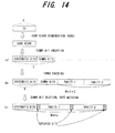
- Fig. 14 explains dummy bit insertion processing in the fourth embodiment;
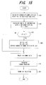
- Fig. 15 shows the flow of dummy bit insertion processing, in which the transmission processing portion has the same configuration as in the first embodiment in Fig. 1 .
- the dummy bit size is adjusted such that the total size K1 is equal to the stipulated size Z.
- the encoding portion 24 encodes the code block with dummy bits inserted, by for example performing turbo encoding ((b) in Fig. 14 ; step 606).
- the physical layer HARQ function portion 25 deletes the dummy bits from the systematic bits, and performs rate matching such that the code length is equal to Ndata ((c) in Fig. 14 ; step 607). Thereafter processing similar to that of the prior art is performed, and systematic code without dummy bits is transmitted. On the receiving side, the systematic code is received, the dummy bits which had been deleted on the transmitting side are inserted into the received systematic code as maximum-likelihood values, turbo decoding is performed, and the information bits are obtained.
- the maximum number of dummy bits can be inserted and the code length made equal to Ndata to perform transmission even when code block segmentation is not performed. Consequently, the effect of dummy bit insertion can be enhanced in a case where code block segmentation is not performed.
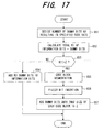
- the fifth embodiment is an embodiment in which, when code block segmentation is performed, the dummy bit size is decided such that the total size in each code block of dummy bits and information bits is a stipulated size Z.
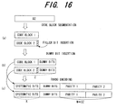
- Fig. 16 explains the dummy bit insertion processing of the fifth embodiment
- Fig. 17 shows the flow of dummy bit insertion processing; the configuration of the transmission processing portion is the same as in the first embodiment of Fig. 1 .
- step 656 filler bits are inserted (step 656), dummy bits are inserted such that the size of each code block is equal to the stipulated size Z ((b) in Fig. 16 ; step 657), and the dummy bit insertion processing ends.
- the encoding portion 24 performs turbo encoding, for example, of each of the code blocks with dummy bits inserted ((c) in Fig. 16 ).
- the physical layer HARQ function portion 25 deletes the dummy bits from the systematic bits, and performs rate matching such that the code length is equal to Ndata. Thereafter, processing similar to that of the prior art is performed, and systematic code without dummy bits is transmitted.
- the systematic code is received, the dummy bits which had been deleted on the transmitting side are inserted into the received systematic code as maximum-likelihood values, turbo decoding is performed, and the information bits are obtained.
- dummy bits are inserted such that the total size of dummy bits and information bits in each code block is equal to the stipulated size Z, encoding is performed, the dummy bits are deleted, and the data is transmitted.
- the size of the inserted dummy bits can be made large, so that the effect of dummy bit insertion can be enhanced.
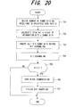
- the sixth embodiment is an embodiment in which dummy bits are inserted before bit scrambling; Fig. 18 explains dummy bit insertion, Fig. 19 is a block diagram of principal portions of the transmission processing portion, and Fig. 20 shows the flow of dummy bit insertion processing.
- the bit scrambling portion 22 performs bit scrambling of information bits with dummy bits inserted, and inputs the result to the code block segmentation portion 23 ((c) in Fig. 18 ; step 704).
- K1 ⁇ Z code segmentation is not performed; if on the other hand K1 > Z, the number of code blocks and code block size are decided, and the segmentation portion 23c performs code block segmentation (step 706). Then, filler bits are inserted (step 707). Thereafter, similarly to the first embodiment, the encoding portion 24 performs turbo encoding of each of the code blocks with dummy bits inserted, and the physical layer HARQ function portion 25 deletes dummy bits and performs prescribed rate matching, and transmits systematic code without dummy bits.
- the systematic code is received, the dummy bits which had been deleted on the transmitting side are inserted as maximum-likelihood values into the received systematic code, turbo decoding is performed, and the information bits are obtained.
- turbo decoding is performed, and the information bits are obtained.
- the seventh embodiment is an embodiment in which dummy bits are inserted after bit scrambling;
- Fig. 21 explains dummy bit insertion
- Fig. 22 is a block diagram of principal portions of the transmission processing portion, and
- Fig. 23 shows the flow of dummy bit insertion processing.
- the bit scrambling portion 22 performs bit scrambling ((b) in Fig. 21 ; step 751) of the information bits ((a) in Fig. 21 ) with CRC bits added by the CRC addition portion 21.
- all-"0"s dummy bits are inappropriate.
- the code block number/code block size judgment portion 23b of the code block segmentation portion 23 compares the magnitudes of the total size K1 of information bits and dummy bits with the stipulated size Z (step 755). If K1 ⁇ Z, code block segmentation is not performed; but if K1 > Z, the number of code blocks and code block size are decided, and the segmentation portion 23c performs code block segmentation (step 756). Then, filler bits are inserted (step 757). Thereafter, similarly to the first embodiment, the encoding portion 24 performs turbo encoding of each of the code blocks with dummy bits inserted, and the physical layer HARQ function portion 25 deletes dummy bits and performs prescribed rate matching, and transmits the systematic code without dummy bits.
- the systematic code is received, the dummy bits which had been deleted on the transmitting side are inserted into the received systematic code as maximum-likelihood values, turbo decoding is performed, and the information bits are obtained.
- the dummy bit insertion portion 31 inserts all-"1"s dummy bits; but as shown in (c) of Fig. 24 , the dummy bit values can be made a random pattern.
- dummy bits can be inserted after bit scrambling.
- the eighth embodiment is an embodiment of dummy bit insertion patterns in the information bits.
- a pattern in which systematic bits and dummy bits are alternated as shown in (a) of Fig. 25 can improve decoding characteristics compared with a pattern in which dummy bits are placed together before and after the information bits.
- an alternating placement pattern is for a case in which the sizes of the systematic bits and dummy bits are the same; when the sizes are different, alternating placement is not possible.
- dummy bits are inserted into systematic bits with dummy bits of only a specified continuous length allowed.
- decoding characteristics decoding error characteristics
- the continuous length of dummy bits is made less than or equal to a preset value, with dummy bits placed in dispersed positions, decoding characteristics (decoding error characteristics) can be improved.
- decoding error characteristics decoding error characteristics
- the continuous length is 2
- two information bits and two dummy bits are placed in alternation as shown in (b) in Fig. 15 .
- the continuous length is 3
- three information bits and three dummy bits are placed in alternation as shown in (c) in Fig. 15 .
- a pattern is possible in which dummy bits are not inserted on the periphery STA and TLA at the beginning and at the end of the information.
- dummy bits are dispersed and inserted in the area excluding the periphery STA and TLA at the beginning and end of the information.
- bit positions A1 to A4 which move to a stipulated number of positions at the beginning and end of the information by interleaving processing are specified in advance, as shown in Fig. 27 .
- Dummy bits are likewise not inserted into these positions A1 to A4 either. The reason for this is the same as that of Fig. 26 .
- 3GPP turbocodes have the characteristic when the code rate reaches a specific value due to puncturing or similar, the characteristic degradation is locally large compared with the peripheral code rates.
- Fig. 28 explains this characteristic degradation;
- A is the decoding characteristic when there is no dummy bit insertion, in which the horizontal axis is the code rate, and the vertical axis is the required Eb/No to obtain a prescribed error rate.
- the decoding characteristic when the code rate reaches a specific value (7/11, 7/9, 7/8), the required Eb/No becomes large compared with the peripheral code rate, and the characteristic is degraded.
- monitoring is performed to determine whether the code rate after puncturing has reached a value close to a specific value (a value in a specific range S1, S2, S3), and if the value is in a specific range S1, S2, S3, dummy bits are inserted prior to puncturing, thereby the decoding characteristic is shifted as indicated by B, and the code rate assumes a value outside the specific ranges S1', S2', S3' determined by the decoding characteristic B is performed, to prevent characteristic degradation.
- the dummy bit insertion amount is determined such that the code rate exists just outside the periphery of the peak in the characteristic B after shifting.
- the transmission processing portion 30 comprises a CRC addition portion 21, bit scrambling portion 22, code block segmentation portion 23, dummy bit insertion control portion 41, channel coding portion (encoding portion) 24, physical layer HARQ function portion 25, physical channel segmentation portion 26, HS-PDSCH interleaving portion 27, constellation rearrangement portion 28, physical channel mapping portion 29, and transmission portion (not shown).
- the dummy bit insertion control portion 41 is provided between the code block segmentation portion 23 and the encoding portion 24, and executes control to determine whether, based on the code rate, dummy bits are inserted into information bits.
- the dummy bit insertion control portion 41 does not insert dummy bits; but if the value is within these ranges, dummy bits are inserted into information bits such that the decoding characteristic is shifted from A to B and the code rate assumes a value outside the specific ranges S1', S2', S3' (step 803).
- dummy bits are inserted such that the code rate does not assume a value in specific ranges which cause degradation of the decoding characteristic, so that degradation of the decoding characteristic can be prevented.
- K0 > K an ideal arrangement in which information bits are not made adjacent in both the first and second inputs, and moreover the information bit insertion positions in both the first and second inputs are equal.
- K0 > K and dummy bits are more numerous than information bits, in principle at least two dummy bits are adjacent. In this case, uniformity is realized by interchanging the roles of the dummy bits and the information bits.
- the ratio of K0 to K is not an integer, and when such an arrangement is not possible due to a positional relationship resulting from interleaving, interchanging of dummy bit positions and information bit positions is allowed. However, this interchanging is performed substantially equally for each of the first and second inputs. For example, as shown in (A) in Fig.
- the positions Q(d) ⁇ 1 adjacent on both sides of the position Q(d) are currently information bits; and when a dummy bit is inserted at each of bit positions (P(Q(d)+1), P(Q(d)-1) in the second input corresponding to the bit positions Q(d) ⁇ 1 in the first input, the bit position (in the figure, P(Q(d)+1) is selected for which the generated dummy bit burst length is shorter. And, as shown in (B) in Fig. 30 , the dummy bit at position Q(d) and the information bit at position Q(d)+1 in the first input are interchanged.
- position Q(d) in the first input is changed from a dummy bit to an information bit
- position Q(d)+1 is changed from an information bit to a dummy bit.
- Fig. 31 shows the flow of an efficient algorithm to modify dummy bit positions so as to satisfy the condition explained in Fig. 30 .
- the input information bit size is K
- the dummy bit size is K0
- the combined bit size is K1
- K+K0 K
- Nd the number of dummy bits of which positions have been determined
- Th 10
- weighting coefficients W(i) are associated with each bit position i as shown in Fig. 32 .
- step 904 if W(i) > Th, i is immediately advanced (step 909), and the processing of step 903 and beyond is continued.
- problems may arise when employing the method, which has been the basis of the embodiments thus far, of uniformly inserting dummy bits into the input information bits.
- the input of the second element encoder of the turbo encoding portion is a pattern resulting from interleaving.
- the dummy bit insertion positions are decided one by one, and the weightings of the adjacent and next-adjacent positions of the dummy bits are increased in both the first and second inputs, so that such positions are not easily selected as dummy bit positions; by this means, dummy bit continuous lengths are kept from becoming long.
- algorithms are not limited to that described above; any algorithm which arranges dummy bit insertion position patterns as uniformly as possible in both the first and second inputs can be adopted in the tenth embodiment.
- a method of deciding the dummy bit size K0 was not explained; but as explained in the second embodiment, the size of the dummy bits to be inserted into information bits is decided based on the specified code rate. Or, as explained in the third embodiment, the size of dummy bits K0 is calculated such that the code size is equal to the bit length Ndata determined by the physical channel transmission rate.
- the turbo encoder of the eleventh embodiment shows the configuration of the turbo encoder of the eleventh embodiment; the first element encoder 24a encodes information bits with dummy bits inserted, the interleaving portion 24b interleaves the information bits with dummy bits inserted, the second element encoder 24c encodes the result of interleaving, and the P/S conversion portion 24e converts the outputs xb, xc of the element encoders 24a, 24b and the information bits xa into series data.
- the first and second dummy bit insertion portions 51, 52 insert dummy bits into the first and second inputs, which are the inputs of the first and second element encoders 24a, 24b.
- the dummy bits be inserted into both the first and the second inputs so as to be widely dispersed overall, and so as to be as uniform as possible.
- the size of dummy bits for insertion K0 is, as explained in the second embodiment, based on a specified code rate and calculated using equation (2), or is, as explained in the third embodiment, calculated using equation (4) such that the code length is equal to the bit length Ndata determined by the physical channel transmission rate.
- Fig. 33 two element encoders are provided; however, a single element encoder can perform the first and second element encoding processing.
- Fig. 34 shows the configuration of the turbo decoder portion on the receiving side which decodes the turbocode encoded by the encoder of Fig.
- first and second dummy bits are same as the first and second dummy bits in the encoder.
- the first element decoder 61 uses ya and yb among the received signals ya, yb, yc to perform decoding.
- the first element decoder 61 is a soft-decision output element decoder, which outputs decoding result likelihoods.
- the first dummy bit deletion portion 62 deletes the first dummy bits from the decoding result of the first element decoder 61, the interleaving portion 63 interleaves the decoding result with dummy bits deleted, and the second dummy bit insertion portion 64 inserts second dummy bits into the interleaved decoding results as maximum-likelihood values.
- the second element decoder 65 performs decoding using the received signal yc and the decoding result of the first element decoder 61, which has been subjected to interleaving and second dummy bit insertion processing.
- the second element encoder 65 is also a soft-decision output element decoder, which outputs decoding result likelihoods.
- the second dummy bit deletion portion 66 deletes the second dummy bits from the decoding output of the second element decoder 65, the deinterleaving portion 67 deinterleaves the decoding result with the dummy bits deleted, and the first dummy bit insert portion 68 inserts the first dummy bits as maximum-likelihood values into the deinterleaved decoding results, and inputs the results to the first element decoder 61.
- the first element decoder 61 uses the output signal of the first dummy bit insertion portion 68 to repeat the above MAP decoding processing. By repeating the above decoding operation a prescribed number of times, the decoding result error rate can be reduced.
- MAP element decoders are used as the first and second element decoders in this turbo element decoder.
- the above processing to delete and add maximum-likelihood reliabilities for dummy bit data is performed in order that a trellis path limited by the dummy bit values is selected; in place of this insertion and deletion, the trellis path can also be selected directly.
- two element decoders are provided; but a single element decoder can perform the first and second element decoding.
- a single dummy bit deletion portion and a single dummy bit insertion portion can be made to perform the first and second dummy bit deletion processing and the first and second dummy bit insertion processing.
- insertion positions can be made mutually independent in both the inputs to the first element encoder 24a and to the second element encoder 24c; in particular, patterns which are uniform overall can be selected for both. Moreover, a dummy bit deletion portion becomes unnecessary.
- dummy bits are inserted into information bits, then the information bits into which the dummy bit inserted are subjected to turbo encoding, and the systematic code obtained by deleting the dummy bits from the turbocode is transmitted; on the receiving side, the systematic code is received, the dummy bits which had been deleted on the transmitting side are inserted into the received systematic code as maximum-likelihood values, and turbo decoding is performed, and by this means decoding errors can be reduced.
- turbo decoding by providing a dummy bit deletion portion in the physical layer HARQ function portion or in the encoding portion, the dummy bits can easily be deleted from systematic bits.
- processing to delete dummy bits from systematic bits can be performed simultaneously with puncturing processing of parity bits of the systematic code. Consequently, dummy bit deletion can be performed so as not to affect the total transmission processing time.
- the size of dummy bits is decided so as to obtain a required code rate, and moreover rate matching can be performed and data is transmitted such that Ndata is the value given by H-ARQ transmission parameters. Further, by uniformly inserting dummy bits, decoding characteristics can be improved. According to this invention, dummy bits can be inserted and data is transmitted with the code rate R made variable, and such that the code length is equal to Ndata.
- the maximum number of dummy bits can be inserted, and the code length can be made equal to Ndata to transmit the data.
- the effect of dummy bit insertion can be improved.
- dummy bits can be inserted, encoding performed, the dummy bits deleted from the results of the encoding, and the data is transmitted such that, in each code block, the total size of the dummy bits and information bits is equal to a stipulated size Z; hence the size of the inserted dummy bits can be made large, so that the effect of dummy bit insertion can be improved.
- dummy bit insertion can be performed either before bit scrambling or after bit scrambling.
- dummy bits are dispersed and inserted into information bits with dummy bit continuous lengths equal to or less than a set value, so that decoding characteristics can be improved.
- dummy bits are dispersed and inserted into information bits excluding the peripheral portions at the beginning and end of the information bits, so that decoding characteristics can be improved.
- dummy bits are dispersed and inserted at the bit positions which do not move to the beginning and end of information by interleaving, so that decoding characteristics can be improved.
- dummy bits are inserted such that the code rate does not assume a specific value which causes degradation of the decoding characteristic, so that degradation of the decoding characteristics can be prevented.
- the patterns of dummy bit insertion positions are made as uniform as possible in both the first and the second inputs, which are the inputs to the first element encoder and to the second element encoder, so that decoding characteristics can be improved.
- dummy bit insertion positions can be determined without mutual dependence of the first and second inputs of the first element encoder and second element encoder, so that dummy bit insertion position patterns can easily be made uniform in the first and second outputs, and decoding characteristics can be improved.
- turbocode within the turbo encoder dummy bits are inserted and parity bits generated, and moreover turbocode can be output without inserting dummy bits into systematic bits, so that a dummy bit deletion portion to delete dummy bits from systematic bits can be made unnecessary.
Landscapes
- Engineering & Computer Science (AREA)
- Computer Networks & Wireless Communication (AREA)
- Signal Processing (AREA)
- Physics & Mathematics (AREA)
- Probability & Statistics with Applications (AREA)
- Theoretical Computer Science (AREA)
- Error Detection And Correction (AREA)
Priority Applications (1)
| Application Number | Priority Date | Filing Date | Title |
|---|---|---|---|
| EP12195538A EP2568613A1 (fr) | 2005-08-12 | 2005-08-12 | Appareil de transmission, appareil de codage et appareil de décodage |
Applications Claiming Priority (1)
| Application Number | Priority Date | Filing Date | Title |
|---|---|---|---|
| PCT/JP2005/014824 WO2007020678A1 (fr) | 2005-08-12 | 2005-08-12 | Appareil de transmission, appareil de codage et appareil de décodage |
Related Child Applications (1)
| Application Number | Title | Priority Date | Filing Date |
|---|---|---|---|
| EP12195538A Division-Into EP2568613A1 (fr) | 2005-08-12 | 2005-08-12 | Appareil de transmission, appareil de codage et appareil de décodage |
Publications (3)
| Publication Number | Publication Date |
|---|---|
| EP1914896A1 true EP1914896A1 (fr) | 2008-04-23 |
| EP1914896A4 EP1914896A4 (fr) | 2012-05-23 |
| EP1914896B1 EP1914896B1 (fr) | 2017-07-26 |
Family
ID=37757350
Family Applications (2)
| Application Number | Title | Priority Date | Filing Date |
|---|---|---|---|
| EP12195538A Withdrawn EP2568613A1 (fr) | 2005-08-12 | 2005-08-12 | Appareil de transmission, appareil de codage et appareil de décodage |
| EP05780226.6A Expired - Lifetime EP1914896B1 (fr) | 2005-08-12 | 2005-08-12 | Appareil de transmission |
Family Applications Before (1)
| Application Number | Title | Priority Date | Filing Date |
|---|---|---|---|
| EP12195538A Withdrawn EP2568613A1 (fr) | 2005-08-12 | 2005-08-12 | Appareil de transmission, appareil de codage et appareil de décodage |
Country Status (5)
| Country | Link |
|---|---|
| US (1) | US8028223B2 (fr) |
| EP (2) | EP2568613A1 (fr) |
| JP (1) | JP4563456B2 (fr) |
| CN (1) | CN101208866B (fr) |
| WO (1) | WO2007020678A1 (fr) |
Cited By (4)
| Publication number | Priority date | Publication date | Assignee | Title |
|---|---|---|---|---|
| US20110093762A1 (en) * | 2008-05-26 | 2011-04-21 | Woo Suk Kwon | Apparatus and method for transmitting data using turbo code |
| EP2645579B1 (fr) * | 2010-11-22 | 2018-09-05 | Saturn Licensing LLC | Dispositif de traitement de données et procédé de traitement de données |
| EP2438511B1 (fr) * | 2010-03-22 | 2019-07-03 | LRDC Systems, LLC | Procédé destiné à identifier et à protéger l'intégrité d'un ensemble de données de source |
| EP4072047A1 (fr) * | 2017-11-16 | 2022-10-12 | Qualcomm Incorporated | Conception de code de détection d'erreur de surdébit réduit pour décoder un mot de code |
Families Citing this family (20)
| Publication number | Priority date | Publication date | Assignee | Title |
|---|---|---|---|---|
| JP2007116592A (ja) * | 2005-10-24 | 2007-05-10 | Kddi Corp | 復号化装置および符号化・復号化システム |
| JP2007116591A (ja) * | 2005-10-24 | 2007-05-10 | Kddi Corp | 符号化装置、復号化装置、および符号化・復号化システム |
| US9686044B2 (en) * | 2007-03-27 | 2017-06-20 | Qualcomm Incorporated | Rate matching with multiple code block sizes |
| CN101431396A (zh) * | 2007-11-09 | 2009-05-13 | 松下电器产业株式会社 | 在拆分码字中分配填充比特的方法 |
| US9130712B2 (en) * | 2008-02-29 | 2015-09-08 | Google Technology Holdings LLC | Physical channel segmentation in wireless communication system |
| JP5194896B2 (ja) * | 2008-03-07 | 2013-05-08 | 沖電気工業株式会社 | 符号化装置、復号装置及び符号化システム |
| JP2010004416A (ja) * | 2008-06-23 | 2010-01-07 | Fujitsu Ltd | 移動無線装置 |
| EP2963828B1 (fr) | 2008-07-02 | 2022-09-07 | Panasonic Intellectual Property Corporation of America | Codage de correction d'effacements pour paquets de différentes tailles utilisant une division de paquets |
| US9215035B2 (en) * | 2008-12-08 | 2015-12-15 | Lg Electronics Inc. | Method of transmitting and receiving physical downlink shared channel in wireless communication system |
| US8726137B2 (en) * | 2009-02-02 | 2014-05-13 | Telefonaktiebolaget L M Ericsson (Publ) | Encoding and decoding methods for expurgated convolutional codes and convolutional turbo codes |
| JP5721316B2 (ja) * | 2009-03-03 | 2015-05-20 | シャープ株式会社 | 送信装置、受信装置および通信システム |
| US8601372B1 (en) | 2012-08-20 | 2013-12-03 | Iboard Incorporated | Digital media album creator |
| TW201218773A (en) * | 2010-10-29 | 2012-05-01 | Altek Corp | Image compression method |
| AU2014379859B2 (en) * | 2014-01-23 | 2017-10-12 | Sony Corporation | Decoding device, decoding method, encoding device, and encoding method |
| CN106160937B (zh) | 2015-04-15 | 2019-01-04 | 中兴通讯股份有限公司 | 一种实现码块分割的方法及装置 |
| HK1258347A1 (zh) * | 2016-03-01 | 2019-11-08 | 苹果公司 | 用於支持低编码速率的turbo编码 |
| US10686472B2 (en) * | 2017-01-20 | 2020-06-16 | Qualcomm Incorporated | Methods and apparatus for achieving low coding rates |
| US11368169B2 (en) | 2017-03-24 | 2022-06-21 | Zte Corporation | Processing method and device for quasi-cyclic low density parity check coding |
| KR102817517B1 (ko) * | 2020-04-20 | 2025-06-10 | 주식회사 엘엑스세미콘 | 데이터구동장치 및 이의 구동 방법 |
| US12142333B2 (en) * | 2022-04-04 | 2024-11-12 | Micron Technology, Inc. | Error correction in a memory device having an error correction code of a predetermined code rate |
Family Cites Families (11)
| Publication number | Priority date | Publication date | Assignee | Title |
|---|---|---|---|---|
| JP3645027B2 (ja) * | 1995-09-20 | 2005-05-11 | 松下電器産業株式会社 | 可変長データ送受信装置 |
| DE10008064B4 (de) | 2000-02-22 | 2009-07-02 | Siemens Ag | Verfahren zum Anpassen der einem Turbo-Codierer zuzuführenden Datenblöcke und entsprechende Kommunikationsvorrichtung |
| US6633856B2 (en) | 2001-06-15 | 2003-10-14 | Flarion Technologies, Inc. | Methods and apparatus for decoding LDPC codes |
| KR100918765B1 (ko) * | 2001-10-20 | 2009-09-24 | 삼성전자주식회사 | 부호분할다중접속 이동통신시스템에서 부호화 및 레이트매칭장치 및 방법 |
| EP1451962B1 (fr) * | 2001-12-10 | 2006-07-26 | Telefonaktiebolaget LM Ericsson (publ) | Procedes et appareils d'adaptation et de decodage de debit |
| US7000173B2 (en) * | 2002-02-11 | 2006-02-14 | Motorola, Inc. | Turbo code based incremental redundancy |
| GB0306549D0 (en) * | 2003-03-21 | 2003-04-23 | Roke Manor Research | A communication method and apparatus |
| KR20050020526A (ko) * | 2003-08-23 | 2005-03-04 | 삼성전자주식회사 | 이동통신시스템에서 비트 인터리빙장치 및 방법 |
| US7334181B2 (en) * | 2003-09-04 | 2008-02-19 | The Directv Group, Inc. | Method and system for providing short block length low density parity check (LDPC) codes |
| CN100391107C (zh) * | 2003-12-25 | 2008-05-28 | 上海贝尔阿尔卡特股份有限公司 | 信道编码方法和装置以及信道译码方法和装置 |
| WO2006075382A1 (fr) | 2005-01-14 | 2006-07-20 | Fujitsu Limited | Méthode de codage, méthode de décodage et dispositif correspondant |
-
2005
- 2005-08-12 EP EP12195538A patent/EP2568613A1/fr not_active Withdrawn
- 2005-08-12 CN CN200580050269XA patent/CN101208866B/zh not_active Expired - Fee Related
- 2005-08-12 EP EP05780226.6A patent/EP1914896B1/fr not_active Expired - Lifetime
- 2005-08-12 JP JP2007530862A patent/JP4563456B2/ja not_active Expired - Fee Related
- 2005-08-12 WO PCT/JP2005/014824 patent/WO2007020678A1/fr not_active Ceased
-
2008
- 2008-02-11 US US12/068,707 patent/US8028223B2/en not_active Expired - Fee Related
Cited By (8)
| Publication number | Priority date | Publication date | Assignee | Title |
|---|---|---|---|---|
| US20110093762A1 (en) * | 2008-05-26 | 2011-04-21 | Woo Suk Kwon | Apparatus and method for transmitting data using turbo code |
| US8522110B2 (en) * | 2008-05-26 | 2013-08-27 | Lg Electronics Inc. | Apparatus and method for transmitting data using turbo code |
| EP2438511B1 (fr) * | 2010-03-22 | 2019-07-03 | LRDC Systems, LLC | Procédé destiné à identifier et à protéger l'intégrité d'un ensemble de données de source |
| EP2645579B1 (fr) * | 2010-11-22 | 2018-09-05 | Saturn Licensing LLC | Dispositif de traitement de données et procédé de traitement de données |
| EP3429084A1 (fr) * | 2010-11-22 | 2019-01-16 | Saturn Licensing LLC | Dispositif et procédé supprimant les bits de remplissage et les bits de parité d'un code concaténé bch/ldpc |
| EP4002700A1 (fr) * | 2010-11-22 | 2022-05-25 | Saturn Licensing LLC | Dispositif et procédé supprimant les bits de remplissage et les bits de parité d'un code concaténé bch/ldpc |
| EP4072047A1 (fr) * | 2017-11-16 | 2022-10-12 | Qualcomm Incorporated | Conception de code de détection d'erreur de surdébit réduit pour décoder un mot de code |
| US11695505B2 (en) | 2017-11-16 | 2023-07-04 | Qualcomm Incorporated | Reduced overhead error detection code design for decoding a codeword |
Also Published As
| Publication number | Publication date |
|---|---|
| JPWO2007020678A1 (ja) | 2009-02-19 |
| EP2568613A1 (fr) | 2013-03-13 |
| EP1914896A4 (fr) | 2012-05-23 |
| EP1914896B1 (fr) | 2017-07-26 |
| CN101208866A (zh) | 2008-06-25 |
| US20080141103A1 (en) | 2008-06-12 |
| JP4563456B2 (ja) | 2010-10-13 |
| CN101208866B (zh) | 2012-05-23 |
| US8028223B2 (en) | 2011-09-27 |
| WO2007020678A1 (fr) | 2007-02-22 |
Similar Documents
| Publication | Publication Date | Title |
|---|---|---|
| US8028223B2 (en) | Transmission device, encoding device and decoding device | |
| US8181099B2 (en) | Transmission device | |
| KR100584170B1 (ko) | 터보 부호화된 복합 재전송 방식 시스템 및 오류 검출 방법 | |
| KR101205488B1 (ko) | 패킷 크기에 기초한 fec코드 레이트 선택 | |
| KR100586343B1 (ko) | 향상된 터보 코드 기반 증분 리던던시 | |
| EP2266239B1 (fr) | Sélection de paramètres de retransmission pour harq dans des réseaux wcdma et lte | |
| JP3701263B2 (ja) | Cdma移動通信システムにおけるデータの送受信装置およびその方法 | |
| US20040187069A1 (en) | Detection, avoidance and/or correction of problematic puncturing patterns in parity bit streams used when implementing turbo codes | |
| US20030079170A1 (en) | Block puncturing for turbo code based incremental redundancy | |
| US7272191B2 (en) | Method and apparatus for producing and processing sequences of modulation symbols | |
| JP5195989B2 (ja) | 送信方法 | |
| WO2006038653A1 (fr) | Appareil de communication sans fil par paquet | |
| JP4841684B2 (ja) | 送信装置及び送信方法 | |
| CN103001649B (zh) | 发送装置 | |
| KR20050119596A (ko) | 차세대 이동통신 시스템에서 고속 데이터 서비스를제공하기 위한 방법 |
Legal Events
| Date | Code | Title | Description |
|---|---|---|---|
| PUAI | Public reference made under article 153(3) epc to a published international application that has entered the european phase |
Free format text: ORIGINAL CODE: 0009012 |
|
| 17P | Request for examination filed |
Effective date: 20080305 |
|
| AK | Designated contracting states |
Kind code of ref document: A1 Designated state(s): DE FR GB IT |
|
| DAX | Request for extension of the european patent (deleted) | ||
| RBV | Designated contracting states (corrected) |
Designated state(s): DE FR GB IT |
|
| A4 | Supplementary search report drawn up and despatched |
Effective date: 20120420 |
|
| RIC1 | Information provided on ipc code assigned before grant |
Ipc: H04L 1/00 20060101ALI20120416BHEP Ipc: H03M 13/29 20060101AFI20120416BHEP |
|
| 17Q | First examination report despatched |
Effective date: 20130904 |
|
| GRAP | Despatch of communication of intention to grant a patent |
Free format text: ORIGINAL CODE: EPIDOSNIGR1 |
|
| RIC1 | Information provided on ipc code assigned before grant |
Ipc: H03M 13/29 20060101AFI20170206BHEP Ipc: H04L 1/18 20060101ALI20170206BHEP Ipc: H04L 1/00 20060101ALI20170206BHEP Ipc: H03M 13/00 20060101ALI20170206BHEP |
|
| INTG | Intention to grant announced |
Effective date: 20170224 |
|
| GRAS | Grant fee paid |
Free format text: ORIGINAL CODE: EPIDOSNIGR3 |
|
| GRAA | (expected) grant |
Free format text: ORIGINAL CODE: 0009210 |
|
| AK | Designated contracting states |
Kind code of ref document: B1 Designated state(s): DE FR GB IT |
|
| REG | Reference to a national code |
Ref country code: GB Ref legal event code: FG4D |
|
| REG | Reference to a national code |
Ref country code: FR Ref legal event code: PLFP Year of fee payment: 13 |
|
| REG | Reference to a national code |
Ref country code: DE Ref legal event code: R096 Ref document number: 602005052418 Country of ref document: DE |
|
| PGFP | Annual fee paid to national office [announced via postgrant information from national office to epo] |
Ref country code: GB Payment date: 20170801 Year of fee payment: 13 Ref country code: IT Payment date: 20170830 Year of fee payment: 13 Ref country code: DE Payment date: 20170802 Year of fee payment: 13 Ref country code: FR Payment date: 20170829 Year of fee payment: 13 |
|
| REG | Reference to a national code |
Ref country code: DE Ref legal event code: R097 Ref document number: 602005052418 Country of ref document: DE |
|
| PLBE | No opposition filed within time limit |
Free format text: ORIGINAL CODE: 0009261 |
|
| STAA | Information on the status of an ep patent application or granted ep patent |
Free format text: STATUS: NO OPPOSITION FILED WITHIN TIME LIMIT |
|
| 26N | No opposition filed |
Effective date: 20180430 |
|
| REG | Reference to a national code |
Ref country code: DE Ref legal event code: R119 Ref document number: 602005052418 Country of ref document: DE |
|
| GBPC | Gb: european patent ceased through non-payment of renewal fee |
Effective date: 20180812 |
|
| PG25 | Lapsed in a contracting state [announced via postgrant information from national office to epo] |
Ref country code: IT Free format text: LAPSE BECAUSE OF NON-PAYMENT OF DUE FEES Effective date: 20180812 Ref country code: DE Free format text: LAPSE BECAUSE OF NON-PAYMENT OF DUE FEES Effective date: 20190301 |
|
| PG25 | Lapsed in a contracting state [announced via postgrant information from national office to epo] |
Ref country code: FR Free format text: LAPSE BECAUSE OF NON-PAYMENT OF DUE FEES Effective date: 20180831 |
|
| PG25 | Lapsed in a contracting state [announced via postgrant information from national office to epo] |
Ref country code: GB Free format text: LAPSE BECAUSE OF NON-PAYMENT OF DUE FEES Effective date: 20180812 |