EP1914902B1 - Verfahren und System für ein Innenraum-Funkkommunikationssystems mit digitaler Verteilung - Google Patents
Verfahren und System für ein Innenraum-Funkkommunikationssystems mit digitaler Verteilung Download PDFInfo
- Publication number
- EP1914902B1 EP1914902B1 EP06301067A EP06301067A EP1914902B1 EP 1914902 B1 EP1914902 B1 EP 1914902B1 EP 06301067 A EP06301067 A EP 06301067A EP 06301067 A EP06301067 A EP 06301067A EP 1914902 B1 EP1914902 B1 EP 1914902B1
- Authority
- EP
- European Patent Office
- Prior art keywords
- digital
- signal
- signals
- sub
- time delay
- Prior art date
- Legal status (The legal status is an assumption and is not a legal conclusion. Google has not performed a legal analysis and makes no representation as to the accuracy of the status listed.)
- Active
Links
Images

Classifications
-
- H—ELECTRICITY
- H04—ELECTRIC COMMUNICATION TECHNIQUE
- H04B—TRANSMISSION
- H04B1/00—Details of transmission systems, not covered by a single one of groups H04B3/00 - H04B13/00; Details of transmission systems not characterised by the medium used for transmission
- H04B1/69—Spread spectrum techniques
- H04B1/707—Spread spectrum techniques using direct sequence modulation
- H04B1/7097—Interference-related aspects
- H04B1/711—Interference-related aspects the interference being multi-path interference
- H04B1/7115—Constructive combining of multi-path signals, i.e. RAKE receivers
Definitions
- the present invention relates to indoor communication systems, particularly inside buildings and tunnels, comprising a digital distribution network.
- Wireless communications systems are becoming an increasingly widespread phenomenon of modern communications. Since many users place an increasing number of cellular calls within buildings or other confined structures, there is a need to achieve high quality indoor coverage.
- a conventional configuration to extend a wireless communication service e.g. GSM or UMTS, from an outdoor environment to an indoor area is shown in Figure 1 and is characterized by the utilization of a repeater R that is typically located within a building B to retransmit within the building a wireless signal Ws received at an external antenna A1 or retransmit outside the building the wireless signals Ws of mobile stations Ms, e.g. mobile phones, handheld computers and the like, located inside the building B.
- a repeater R that is typically located within a building B to retransmit within the building a wireless signal Ws received at an external antenna A1 or retransmit outside the building the wireless signals Ws of mobile stations Ms, e.g. mobile phones, handheld computers and the like, located inside the building B.
- the outdoor wireless signals are passed along a first connection C1 to the repeater R which forwards the signal along a second connection C2 to a plurality of inter-connected amplifiers Am, the amplifiers amplify the signals which are then transmitted over the in-building antennas A2 to A4.
- the repeater R receives said signals along connection C2 and transmits them along connection C1 to the external antenna A1.
- repeater R of the indoor communications structure is replaced by a base station connected to a communications core network along connection C1.
- Connections C1 and C2 may be a radio frequency (RF) connection or network, e.g. using coaxial cable, an optical connection or network, e.g. using optical fiber, an electro-optical network, that is, when the wireless signal transmitted along the cable changes between electrical and optical transmission, or a high-speed data distribution network such as an Ethernet network.
- RF radio frequency
- the in-building antennas A2 to A4 may also be implemented as RF radiating cables. This is typically the case when the wireless signals shall be propagated in tunnels.
- US 2006/233111 A1 discloses a modular test chassis for use in testing wireless devices including a channel emulation module.
- the module comprises circuitry for emulating the effects of a dynamic physical environment including multipath effect and delay lines on signals in the transmission channel.
- the delay lines are coupled to a splitter/combiner and may be fixed or programmable devices which add delay to N versions of the signal.
- a latency measurement system applies timestamps frames as they are transmitted and received at the test module for improved latency measurement accuracy.
- the object of the present is to provide a method and a system for indoor communications which improves the quality of the wireless indoor service coverage.
- the object is achieved by a method for indoor communications according to claim 1 and/or 2, a multi-path arrangement according to claim 3, a transmitting or receiving unit according to claim 6, a digital distribution network according to claim 7 and an indoor communications system according to claim 8.
- the basic idea behind the invention arises from the observation that in indoor or confined environments the multi-path time delay of the radio signals reaching or transmitted by a mobile station is shorter than the minimum needed for a rake receiver of the mobile station or a base station to work properly i.e. at least one chip length (e.g. 260 ns for UMTS). In such cases then there is no benefit from the technical advantages of the rake receivers, already present in the mobile stations, in order to achieve improved reception i.e. a rake receiver shows a higher Signal to Noise Ratio (SNR) in a multi-path environment than in an environment without multi-path effects.
- SNR Signal to Noise Ratio
- the method and system for indoor communications according to the invention allows the generation of signals having multi-path time delays of at least one chip length. According to the invention, combining a plurality of substantially identical sub-signals showing different time delays between them of at least one chip length, generates a new signal showing a behavior similar to a radio signal in an outdoor multi-path environment.
- the solution can be applicable for indoor downlink or uplink transmission or both for indoor downlink and uplink transmission.
- signal uplink direction that is from mobile station to the base station
- the rake receiver of the base station receives signals with multi-path delays greater than 1 chip length
- signal downlink direction that is from the base station to the mobile station
- the rake receiver of the mobile station receives signals with multi-path delays greater than 1 chip length
- the solution is preferably adapted for transmission of signals to and from a mobile station located in a confined area, such as a building or a tunnel, using at least a digital transmission network.
- the system for indoor communications comprises a digital network for distribution of signals between a base station and a digital remote unit which provides the signals to an indoor antenna or radiating cable.
- a digital distribution network is any network in which information is sent in digital form using any known physical transmission medium.
- the digital remote units comprise digital transmitting or receiving means for transmitting or receiving the digital signals along the digital distribution network.
- the digital network according to the invention is used advantageously to improve the service performance for radio communications into buildings and tunnels which do not provide system conditions sufficient to benefit from the rake receivers of mobile stations or base stations using, for example, CDMA or UMTS communication technology.
- Figure 1 shows a conventional indoor communications system structure.
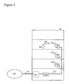
- Figure 2 shows an example structure of an indoor communications system according to the invention.
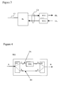
- Figure 3 shows an exemplary detail of an indoor communications system according to the invention.
- Figure 4 shows a multi-path arrangement according to the invention.
- FIG. 2 An example of an indoor communications system structure according to the invention, located inside a building B, is shown in Figure 2 , comprising a base station Bs, a digital distribution network C2, a multi-path arrangement MA, three digital remote units RD and three in-building antennas A2 to A4.
- the base station Bs is connected to a core network CN along a first connection network C1 and the indoor antennas A2 to A4 send and receive radio signals Ws to/from a mobile station Ms.
- communications core network CN signals intended for the mobile station Ms are received by the base station Bs along connection C1. Said signals are then passed through the base station digital interface to the digital network C2 for distribution.
- the digital network comprises the multi-path arrangement MA where the digital signals are split into at least two substantially identical digital sub-signals, a different time delay is applied to each individual digital sub-signal so that the at least two substantially identical digital sub-signals have a time delay difference of at least 1 chip length, and subsequently the digital sub-signals are combined.
- Said combined signals at the output of the multi-path arrangement MA are distributed to the digital remote units RD, which adapt the received RF signal, e.g.
- the performance of rake receivers within the mobile stations of the building is optimized and the quality of reception in such an environment is improved.
- radio signals Ws transmitted by the mobile station Ms located inside the building are received by the in-building antenna A2 and passed in to the digital remote unit RD, which adapts the signals, e.g. with the use of an analog-to-digital converter and/or analog-to-digital amplifier, for transmission through the digital connection C2 to the multi-path arrangement MA.
- said received digital signals are split into at least two substantially identical digital sub-signals, a different time delay is applied to each individual digital sub-signal so that the at least two substantially identical digital sub-signals have a time delay difference of at least 1 chip length, and subsequently the digital sub-signals are combined.
- Said combined signals at the output of the multi-path arrangement MA are distributed to the base station Bs, which provides said signals, in appropriate form, to a rake receiver within the base station which is in charge of processing the multi-path signal components of the digital signal and obtain the transmitted mobile station signal. Said signal is then forwarded to the communications core network CN.
- Figure 3 shows an exemplary detail of an indoor communications system comprising a first connections network C1, a base station Bs, a digital distribution network C2 and two multi-path arrangements MA1 and MA2 according to the invention, the first for downlink transmission DL and the second for uplink transmission UL.
- Figure 4 shows an example of a multi-path arrangement MA according to the invention for a digital distribution network, comprising a digital signal input port A, a digital signal output port B, two digital transmission lines D1 and D2, a digital splitter DS and a digital combiner DC, nodes C,D, E and F, and a digital delay unit DDU.
- the digital signal input A is connected to the digital splitter DS which splits an incoming digital signal in two substantially identical digital sub-signals and outputs them in nodes C and E.
- a first digital transmission line D1 is connected between output node C of the digital splitter DS and input node D of the digital combiner DC.
- a second digital transmission line D2 is connected between output node E of the digital splitter DS and input node F of the digital combiner DC.
- a digital delay unit DDU is arranged in the first digital transmission line D1.
- the digital combiner DC combines the two incoming digital sub-signals into a single digital signal at output port B.
- the digital splitter DS splits an incoming digital signal that is fed in input port A into two substantially identical digital sub-signals. Those two digital sub-signals take two different signal paths ACDB and AEFB.
- the signal path ACDB introduces a time delay of at least one chip length, e.g. at least 260 ns for UMTS, to that digital sub-signal.
- the digital combiner DC combines the two digital sub-signals after passing through their individual signal paths ACD and AEF to a new digital output signal showing a behavior similar to a signal in a multi-path environment.
- An incoming signal is then split into a number "n+1" of substantially identical digital sub-signals equal to the number of signal paths.
- the new combined signal comprises the necessary characteristics needed for the rake receivers present in mobile stations and base stations to demodulate this signal. This enables the activation of the so-called rake effect providing a higher SNR in receivers of node base stations and mobile phones.
- the digital delay unit ODU can be implemented by any general known means and can provide a variable and adjustable time delay.
- the multi-path arrangement of Figure 4 only shows one digital delay unit DDU arranged in the first digital transmission line D1, it is possible to arrange a second digital delay unit in the second digital transmission line D2, as long as the condition that the first signal path ACDB introduces a time delay of at least one chip length greater than the time delay introduced by the second signal path AEFB.
- the multi-path arrangement MA described herein can be implemented in hardware or software form i.e. the digitalized input can be processed according to the invention inside a processor or a program running on a computer. It is also understood that although presented in the figures as a standalone arrangement of the digital transmission network of the indoor communications system said functionality can also be implemented inside the digital repeater or the base station of the indoor communications system.
Landscapes
- Engineering & Computer Science (AREA)
- Computer Networks & Wireless Communication (AREA)
- Signal Processing (AREA)
- Mobile Radio Communication Systems (AREA)
- Radio Relay Systems (AREA)
Claims (7)
- Verfahren für die Innenraumkommunikation, wobei das Verfahren umfasst:Eine Basisstation (Bs), welche ein für eine sich innerhalb einer begrenzten Umgebung (8) befindliche Mobilstation (Ms) bestimmtes Signal empfängt,wobei die Basisstation das besagte Signal für die Übertragung über ein digitales Netzwerk (C2) anpasst,wobei das digitale Netzwerk (C2) das digitale Signal an eine entfernte digitale Einheit (RD) verteilt welche das digitale Signal für die Übertragung über ein drahtloses Übertragungsmittel (A2 bis A4) anpasst,wobei die Mobilstation (Ms) das von dem drahtlosen Übertragungsmittel (A2 bis A4) übertragene Signal empfängt und das besagte Signal an einen Rake-Empfänger bereitstellt,wobei das Verfahren gekennzeichnet ist durch
in einer Mehrpfadanordnung (MA), welche innerhalb des digitalen Netzwerks angeordnet ist, Aufspalten des digitalen Signals in mindestens zwei im Wesentlichen identische Teilsignale, Anwenden einer unterschiedlichen Zeitverzögerung für jedes einzeine digitale Teilsignal, so dass die Zeitverzögerungsdifferenz zwischen den digitalen Teilsignalen mindestens eine Chiplänge beträgt, und Kombinieren der mindestens zwei digitalen Teilsignale mit unterschiedlichen Zeitverzögerungen. - Verfahren für die Innenraumkommunikation, wobei das Verfahren umfasst:Ein drahtloses Empfangsmittel (A2 bis A4) zum Empfangen eines drahtlosen Signals (Ws) von einer sich innerhalb einer begrenzten Umgebung (B) befindlichen Mobilstation (Ms),wobei das drahtlose Empfangsmittel das empfangene Signale an eine entfernte digitale Einheit (RD) weiterleitet, welche das Signal für die Übertragung über ein digitales Netzwerk (C2) anpasst,wobei das digitale Netzwerk (C2) das digitale Signal an eine Basisstation (Bs) verteilt und die Basisstation (Bs) das empfangene Signal an einen Rake-Empfänger bereitstellt,wobei das Verfahren gekennzeichnet ist durch
in einer Mehrpfadanordnung (MA), welche innerhalb des digitalen Netzwerks angeordnet ist, Aufspalten des digitalen Signals in mindestens zwei im Wesentlichen identische Teilsignale, Anwenden einer unterschiedlichen Zeitverzögerung für jedes einzelne digitale Teilsignal, so dass die Zeitverzögerungsdifferenz zwischen den digitalen Zeitsignalen mindestens eine Chiplänge beträgt, und Kombinieren der mindestens zwei digitalen Teilsignale mit unterschiedlichen Zeitverzögerungen. - Mehrpfadanordnung (MA) zum Anpassen eines einzelnen digitalen Ausgangssignals für einen Rake-Empfänger in einer Mobilstation (Ms), welche sich innerhalb einer begrenzten Umgebung (B) befindet, wobei das besagte Ausgangssignal von einem digitalen Netzwerk (C2) eines Innenraum-Kommunikationsystems verteilt wird, umfassend Mittel zum
Aufspalten eines eingehenden digitalen Signals in mindestens zwei identische digitale Teilsignale,
Bereitstellen eines jeden digitalen Teilsignals an signalpfad (AEFB, ACDB) Anwenden einer unterschiedlichen Zeitverzögerung für jedes einzelne digital Teilsignal, so dass die Zeitverzögerungsdifferenz zwischen den digitalen Zeitsignalen mindestens eine Chiplänge beträgt, und
Kombinieren der mindestens zwei digitalen Teilsignale mit unterschiedlichen Zeitverzögerungen in das besagte einzelne digitale Ausgangssignal. - Die Mehrpfadanordnurig (MA) nach Anspruch 3, wobei die Zeitverzögerungsdifferenz zwischen den Signalpfaden (AEFB, ACDB) der mindestens zwei einzelnen digitalen Teilsignale ein Vielfaches einer Chiplänge ist.
- Die Mehrpfadanordnung (MA) nach Anspruch 3, wobei zumindest der erste Signalpfad (ACDB) eine digitale Verzögerüngseinheit (DDU) umfasst.
- Ein digitales Übertragungsnetzwerk (C2) mit einer Mehrpfadanordnung (MA) an einem Ende und einer Sende- und/oder Empfangseinheit (Bs, RD) an dem anderen Ende für die Verteilung des besagten Signals, nach einem beliebigen der Ansprüche 3 bis 5.
- Ein Innenraum-Kommunikationssystem mit einer Mehrpfadanordnung (MA) nach einem beliebigen der Ansprüche 3 bis 5.
Priority Applications (3)
| Application Number | Priority Date | Filing Date | Title |
|---|---|---|---|
| EP06301067A EP1914902B1 (de) | 2006-10-20 | 2006-10-20 | Verfahren und System für ein Innenraum-Funkkommunikationssystems mit digitaler Verteilung |
| DE602006013834T DE602006013834D1 (de) | 2006-10-20 | 2006-10-20 | Verfahren und System für ein Innenraum-Funkkommunikationssystems mit digitaler Verteilung |
| AT06301067T ATE465558T1 (de) | 2006-10-20 | 2006-10-20 | Verfahren und system für ein innenraum- funkkommunikationssystems mit digitaler verteilung |
Applications Claiming Priority (1)
| Application Number | Priority Date | Filing Date | Title |
|---|---|---|---|
| EP06301067A EP1914902B1 (de) | 2006-10-20 | 2006-10-20 | Verfahren und System für ein Innenraum-Funkkommunikationssystems mit digitaler Verteilung |
Publications (2)
| Publication Number | Publication Date |
|---|---|
| EP1914902A1 EP1914902A1 (de) | 2008-04-23 |
| EP1914902B1 true EP1914902B1 (de) | 2010-04-21 |
Family
ID=37876005
Family Applications (1)
| Application Number | Title | Priority Date | Filing Date |
|---|---|---|---|
| EP06301067A Active EP1914902B1 (de) | 2006-10-20 | 2006-10-20 | Verfahren und System für ein Innenraum-Funkkommunikationssystems mit digitaler Verteilung |
Country Status (3)
| Country | Link |
|---|---|
| EP (1) | EP1914902B1 (de) |
| AT (1) | ATE465558T1 (de) |
| DE (1) | DE602006013834D1 (de) |
Family Cites Families (3)
| Publication number | Priority date | Publication date | Assignee | Title |
|---|---|---|---|---|
| CN101365245A (zh) * | 2002-06-28 | 2009-02-11 | 诺基亚公司 | 用于分布式bts体系结构的位置服务支持 |
| US7693082B2 (en) * | 2005-04-12 | 2010-04-06 | Azimuth Systems, Inc. | Latency measurement apparatus and method |
| US20060229019A1 (en) * | 2005-04-12 | 2006-10-12 | Azimuth Systems, Inc. | Channel sounding method and apparatus |
-
2006
- 2006-10-20 DE DE602006013834T patent/DE602006013834D1/de active Active
- 2006-10-20 AT AT06301067T patent/ATE465558T1/de not_active IP Right Cessation
- 2006-10-20 EP EP06301067A patent/EP1914902B1/de active Active
Also Published As
| Publication number | Publication date |
|---|---|
| EP1914902A1 (de) | 2008-04-23 |
| ATE465558T1 (de) | 2010-05-15 |
| DE602006013834D1 (de) | 2010-06-02 |
Similar Documents
| Publication | Publication Date | Title |
|---|---|---|
| JP5575230B2 (ja) | Cdmaビーコンパイロットを分散型リモートアンテナノードの出力に挿入する方法 | |
| US11695467B2 (en) | Reconfigurable and modular active repeater device | |
| KR100216349B1 (ko) | 코드분할다중접속 통신시스템의 전파중계장치 | |
| CA2087285C (en) | Rf repeaters for time division duplex cordless telephone systems | |
| WO2015133863A1 (en) | Antenna array self-calibration | |
| US11206599B2 (en) | Main unit and distributed antenna system including the same | |
| CN106357310B (zh) | 多输入多输出信号传输方法和系统 | |
| US11483057B2 (en) | Base station signal matching device, and base station interface unit and distributed antenna system including the same | |
| CN206196066U (zh) | 一种射频拉远模块及应用该模块的信号传输系统 | |
| KR20010039183A (ko) | 이동통신 시스템의 다중경로 중계방법 및 그 장치 | |
| EP1391047A1 (de) | Vorrichtung zur vergrösserung der kapazität zwischen sendern und empfängern in drahtlosen netzwerken kurzer reichweite | |
| EP1914902B1 (de) | Verfahren und System für ein Innenraum-Funkkommunikationssystems mit digitaler Verteilung | |
| EP1914903B1 (de) | Verfahren und System für ein Innenraum-Funkkommunikationssystems mit Verteilung von Hochfrequenzsignalen | |
| EP1914911A1 (de) | Innenraumkommunikationssystem und Verfahren mit optischer Verteilung | |
| EP1916780A2 (de) | Anordnung und Verfahren zur Emulierung einer Mehrwegumgebung in einem Funknetz, das sich in einer mehrwegeffektfreien Umgebung befindet oder in diese hineinreicht | |
| JP2008136002A (ja) | 無線通信システムおよび無線基地局 | |
| KR101427644B1 (ko) | 실내 안테나 시스템 | |
| KR101236408B1 (ko) | 다중 중계기 시스템의 연결형 기지국 신호 분배장치 | |
| US20110216754A1 (en) | Time delay transmit diversity radiofrequency device | |
| KR100257187B1 (ko) | 디지탈 이동통신에 있어서 다중 경로 상호간섭 제거장치 | |
| CN111786697A (zh) | 一种天线控制系统及电子设备 | |
| KR20190075338A (ko) | 통신 시스템 | |
| KR20150008692A (ko) | 하이브리드 커플러를 구비하는 실내용 미모 안테나를 포함하는 실내 안테나 시스템 |
Legal Events
| Date | Code | Title | Description |
|---|---|---|---|
| PUAI | Public reference made under article 153(3) epc to a published international application that has entered the european phase |
Free format text: ORIGINAL CODE: 0009012 |
|
| 17P | Request for examination filed |
Effective date: 20071031 |
|
| AK | Designated contracting states |
Kind code of ref document: A1 Designated state(s): AT BE BG CH CY CZ DE DK EE ES FI FR GB GR HU IE IS IT LI LT LU LV MC NL PL PT RO SE SI SK TR |
|
| AX | Request for extension of the european patent |
Extension state: AL BA HR MK RS |
|
| AKX | Designation fees paid |
Designated state(s): AT BE BG CH CY CZ DE DK EE ES FI FR GB GR HU IE IS IT LI LT LU LV MC NL PL PT RO SE SI SK TR |
|
| AXX | Extension fees paid |
Extension state: HR Payment date: 20081023 Extension state: AL Payment date: 20081023 Extension state: BA Payment date: 20081023 Extension state: RS Payment date: 20081023 |
|
| GRAP | Despatch of communication of intention to grant a patent |
Free format text: ORIGINAL CODE: EPIDOSNIGR1 |
|
| GRAS | Grant fee paid |
Free format text: ORIGINAL CODE: EPIDOSNIGR3 |
|
| GRAA | (expected) grant |
Free format text: ORIGINAL CODE: 0009210 |
|
| AK | Designated contracting states |
Kind code of ref document: B1 Designated state(s): AT BE BG CH CY CZ DE DK EE ES FI FR GB GR HU IE IS IT LI LT LU LV MC NL PL PT RO SE SI SK TR |
|
| AX | Request for extension of the european patent |
Extension state: AL BA HR RS |
|
| REG | Reference to a national code |
Ref country code: GB Ref legal event code: FG4D |
|
| REG | Reference to a national code |
Ref country code: CH Ref legal event code: EP |
|
| REG | Reference to a national code |
Ref country code: IE Ref legal event code: FG4D |
|
| REF | Corresponds to: |
Ref document number: 602006013834 Country of ref document: DE Date of ref document: 20100602 Kind code of ref document: P |
|
| REG | Reference to a national code |
Ref country code: NL Ref legal event code: VDEP Effective date: 20100421 |
|
| LTIE | Lt: invalidation of european patent or patent extension |
Effective date: 20100421 |
|
| PG25 | Lapsed in a contracting state [announced via postgrant information from national office to epo] |
Ref country code: ES Free format text: LAPSE BECAUSE OF FAILURE TO SUBMIT A TRANSLATION OF THE DESCRIPTION OR TO PAY THE FEE WITHIN THE PRESCRIBED TIME-LIMIT Effective date: 20100801 Ref country code: LT Free format text: LAPSE BECAUSE OF FAILURE TO SUBMIT A TRANSLATION OF THE DESCRIPTION OR TO PAY THE FEE WITHIN THE PRESCRIBED TIME-LIMIT Effective date: 20100421 Ref country code: SE Free format text: LAPSE BECAUSE OF FAILURE TO SUBMIT A TRANSLATION OF THE DESCRIPTION OR TO PAY THE FEE WITHIN THE PRESCRIBED TIME-LIMIT Effective date: 20100421 Ref country code: NL Free format text: LAPSE BECAUSE OF FAILURE TO SUBMIT A TRANSLATION OF THE DESCRIPTION OR TO PAY THE FEE WITHIN THE PRESCRIBED TIME-LIMIT Effective date: 20100421 |
|
| PG25 | Lapsed in a contracting state [announced via postgrant information from national office to epo] |
Ref country code: SI Free format text: LAPSE BECAUSE OF FAILURE TO SUBMIT A TRANSLATION OF THE DESCRIPTION OR TO PAY THE FEE WITHIN THE PRESCRIBED TIME-LIMIT Effective date: 20100421 Ref country code: AT Free format text: LAPSE BECAUSE OF FAILURE TO SUBMIT A TRANSLATION OF THE DESCRIPTION OR TO PAY THE FEE WITHIN THE PRESCRIBED TIME-LIMIT Effective date: 20100421 Ref country code: FI Free format text: LAPSE BECAUSE OF FAILURE TO SUBMIT A TRANSLATION OF THE DESCRIPTION OR TO PAY THE FEE WITHIN THE PRESCRIBED TIME-LIMIT Effective date: 20100421 Ref country code: IS Free format text: LAPSE BECAUSE OF FAILURE TO SUBMIT A TRANSLATION OF THE DESCRIPTION OR TO PAY THE FEE WITHIN THE PRESCRIBED TIME-LIMIT Effective date: 20100821 Ref country code: LV Free format text: LAPSE BECAUSE OF FAILURE TO SUBMIT A TRANSLATION OF THE DESCRIPTION OR TO PAY THE FEE WITHIN THE PRESCRIBED TIME-LIMIT Effective date: 20100421 |
|
| PG25 | Lapsed in a contracting state [announced via postgrant information from national office to epo] |
Ref country code: GR Free format text: LAPSE BECAUSE OF FAILURE TO SUBMIT A TRANSLATION OF THE DESCRIPTION OR TO PAY THE FEE WITHIN THE PRESCRIBED TIME-LIMIT Effective date: 20100722 Ref country code: PL Free format text: LAPSE BECAUSE OF FAILURE TO SUBMIT A TRANSLATION OF THE DESCRIPTION OR TO PAY THE FEE WITHIN THE PRESCRIBED TIME-LIMIT Effective date: 20100421 Ref country code: CY Free format text: LAPSE BECAUSE OF FAILURE TO SUBMIT A TRANSLATION OF THE DESCRIPTION OR TO PAY THE FEE WITHIN THE PRESCRIBED TIME-LIMIT Effective date: 20100526 |
|
| PG25 | Lapsed in a contracting state [announced via postgrant information from national office to epo] |
Ref country code: DK Free format text: LAPSE BECAUSE OF FAILURE TO SUBMIT A TRANSLATION OF THE DESCRIPTION OR TO PAY THE FEE WITHIN THE PRESCRIBED TIME-LIMIT Effective date: 20100421 Ref country code: PT Free format text: LAPSE BECAUSE OF FAILURE TO SUBMIT A TRANSLATION OF THE DESCRIPTION OR TO PAY THE FEE WITHIN THE PRESCRIBED TIME-LIMIT Effective date: 20100823 Ref country code: EE Free format text: LAPSE BECAUSE OF FAILURE TO SUBMIT A TRANSLATION OF THE DESCRIPTION OR TO PAY THE FEE WITHIN THE PRESCRIBED TIME-LIMIT Effective date: 20100421 |
|
| PLBE | No opposition filed within time limit |
Free format text: ORIGINAL CODE: 0009261 |
|
| STAA | Information on the status of an ep patent application or granted ep patent |
Free format text: STATUS: NO OPPOSITION FILED WITHIN TIME LIMIT |
|
| PG25 | Lapsed in a contracting state [announced via postgrant information from national office to epo] |
Ref country code: BE Free format text: LAPSE BECAUSE OF FAILURE TO SUBMIT A TRANSLATION OF THE DESCRIPTION OR TO PAY THE FEE WITHIN THE PRESCRIBED TIME-LIMIT Effective date: 20100421 Ref country code: CZ Free format text: LAPSE BECAUSE OF FAILURE TO SUBMIT A TRANSLATION OF THE DESCRIPTION OR TO PAY THE FEE WITHIN THE PRESCRIBED TIME-LIMIT Effective date: 20100421 Ref country code: RO Free format text: LAPSE BECAUSE OF FAILURE TO SUBMIT A TRANSLATION OF THE DESCRIPTION OR TO PAY THE FEE WITHIN THE PRESCRIBED TIME-LIMIT Effective date: 20100421 Ref country code: SK Free format text: LAPSE BECAUSE OF FAILURE TO SUBMIT A TRANSLATION OF THE DESCRIPTION OR TO PAY THE FEE WITHIN THE PRESCRIBED TIME-LIMIT Effective date: 20100421 |
|
| 26N | No opposition filed |
Effective date: 20110124 |
|
| PGFP | Annual fee paid to national office [announced via postgrant information from national office to epo] |
Ref country code: IT Payment date: 20101022 Year of fee payment: 5 |
|
| PG25 | Lapsed in a contracting state [announced via postgrant information from national office to epo] |
Ref country code: MC Free format text: LAPSE BECAUSE OF NON-PAYMENT OF DUE FEES Effective date: 20101031 |
|
| REG | Reference to a national code |
Ref country code: CH Ref legal event code: PL |
|
| PG25 | Lapsed in a contracting state [announced via postgrant information from national office to epo] |
Ref country code: LI Free format text: LAPSE BECAUSE OF NON-PAYMENT OF DUE FEES Effective date: 20101031 Ref country code: CH Free format text: LAPSE BECAUSE OF NON-PAYMENT OF DUE FEES Effective date: 20101031 |
|
| PG25 | Lapsed in a contracting state [announced via postgrant information from national office to epo] |
Ref country code: IE Free format text: LAPSE BECAUSE OF NON-PAYMENT OF DUE FEES Effective date: 20101020 |
|
| PG25 | Lapsed in a contracting state [announced via postgrant information from national office to epo] |
Ref country code: IT Free format text: LAPSE BECAUSE OF NON-PAYMENT OF DUE FEES Effective date: 20111020 |
|
| PG25 | Lapsed in a contracting state [announced via postgrant information from national office to epo] |
Ref country code: BG Free format text: LAPSE BECAUSE OF FAILURE TO SUBMIT A TRANSLATION OF THE DESCRIPTION OR TO PAY THE FEE WITHIN THE PRESCRIBED TIME-LIMIT Effective date: 20100421 Ref country code: HU Free format text: LAPSE BECAUSE OF FAILURE TO SUBMIT A TRANSLATION OF THE DESCRIPTION OR TO PAY THE FEE WITHIN THE PRESCRIBED TIME-LIMIT Effective date: 20101022 Ref country code: LU Free format text: LAPSE BECAUSE OF NON-PAYMENT OF DUE FEES Effective date: 20101020 |
|
| PG25 | Lapsed in a contracting state [announced via postgrant information from national office to epo] |
Ref country code: TR Free format text: LAPSE BECAUSE OF FAILURE TO SUBMIT A TRANSLATION OF THE DESCRIPTION OR TO PAY THE FEE WITHIN THE PRESCRIBED TIME-LIMIT Effective date: 20100421 |
|
| PG25 | Lapsed in a contracting state [announced via postgrant information from national office to epo] |
Ref country code: BG Free format text: LAPSE BECAUSE OF FAILURE TO SUBMIT A TRANSLATION OF THE DESCRIPTION OR TO PAY THE FEE WITHIN THE PRESCRIBED TIME-LIMIT Effective date: 20100721 |
|
| REG | Reference to a national code |
Ref country code: FR Ref legal event code: GC Effective date: 20131018 |
|
| REG | Reference to a national code |
Ref country code: FR Ref legal event code: RG Effective date: 20141016 |
|
| REG | Reference to a national code |
Ref country code: FR Ref legal event code: CA Effective date: 20150521 |
|
| REG | Reference to a national code |
Ref country code: FR Ref legal event code: CA Effective date: 20150521 |
|
| REG | Reference to a national code |
Ref country code: FR Ref legal event code: PLFP Year of fee payment: 10 |
|
| REG | Reference to a national code |
Ref country code: FR Ref legal event code: PLFP Year of fee payment: 11 |
|
| REG | Reference to a national code |
Ref country code: FR Ref legal event code: PLFP Year of fee payment: 12 |
|
| REG | Reference to a national code |
Ref country code: DE Ref legal event code: R082 Ref document number: 602006013834 Country of ref document: DE Representative=s name: METACOM LEGAL RECHTSANWAELTE, DE Ref country code: DE Ref legal event code: R082 Ref document number: 602006013834 Country of ref document: DE Representative=s name: METACOM LEGAL, DE Ref country code: DE Ref legal event code: R081 Ref document number: 602006013834 Country of ref document: DE Owner name: WSOU INVESTMENTS, LLC, LOS ANGELES, US Free format text: FORMER OWNER: ALCATEL LUCENT, PARIS, FR Ref country code: DE Ref legal event code: R082 Ref document number: 602006013834 Country of ref document: DE Representative=s name: BARKHOFF REIMANN VOSSIUS, DE |
|
| REG | Reference to a national code |
Ref country code: GB Ref legal event code: 732E Free format text: REGISTERED BETWEEN 20200827 AND 20200902 |
|
| REG | Reference to a national code |
Ref country code: DE Ref legal event code: R082 Ref document number: 602006013834 Country of ref document: DE Representative=s name: METACOM LEGAL RECHTSANWAELTE, DE Ref country code: DE Ref legal event code: R082 Ref document number: 602006013834 Country of ref document: DE Representative=s name: METACOM LEGAL, DE Ref country code: DE Ref legal event code: R082 Ref document number: 602006013834 Country of ref document: DE Representative=s name: METACOM LEGAL NAGEL MARKOWSKY VOSSIUS RECHTSAN, DE |
|
| P01 | Opt-out of the competence of the unified patent court (upc) registered |
Effective date: 20230606 |
|
| PGFP | Annual fee paid to national office [announced via postgrant information from national office to epo] |
Ref country code: GB Payment date: 20260227 Year of fee payment: 20 |
|
| PGFP | Annual fee paid to national office [announced via postgrant information from national office to epo] |
Ref country code: DE Payment date: 20260327 Year of fee payment: 20 |
|
| PGFP | Annual fee paid to national office [announced via postgrant information from national office to epo] |
Ref country code: FR Payment date: 20260325 Year of fee payment: 20 |