EP1914963A1 - Ressort à torsions multiples et dispositif coulissant semi-automatique l'utilisant - Google Patents
Ressort à torsions multiples et dispositif coulissant semi-automatique l'utilisant Download PDFInfo
- Publication number
- EP1914963A1 EP1914963A1 EP07118678A EP07118678A EP1914963A1 EP 1914963 A1 EP1914963 A1 EP 1914963A1 EP 07118678 A EP07118678 A EP 07118678A EP 07118678 A EP07118678 A EP 07118678A EP 1914963 A1 EP1914963 A1 EP 1914963A1
- Authority
- EP
- European Patent Office
- Prior art keywords
- coil spring
- semi
- section
- sliding
- sliding device
- Prior art date
- Legal status (The legal status is an assumption and is not a legal conclusion. Google has not performed a legal analysis and makes no representation as to the accuracy of the status listed.)
- Withdrawn
Links
Images



Classifications
-
- H—ELECTRICITY
- H04—ELECTRIC COMMUNICATION TECHNIQUE
- H04B—TRANSMISSION
- H04B1/00—Details of transmission systems, not covered by a single one of groups H04B3/00 - H04B13/00; Details of transmission systems not characterised by the medium used for transmission
- H04B1/38—Transceivers, i.e. devices in which transmitter and receiver form a structural unit and in which at least one part is used for functions of transmitting and receiving
-
- H—ELECTRICITY
- H04—ELECTRIC COMMUNICATION TECHNIQUE
- H04M—TELEPHONIC COMMUNICATION
- H04M1/00—Substation equipment, e.g. for use by subscribers
- H04M1/02—Constructional features of telephone sets
- H04M1/0202—Portable telephone sets, e.g. cordless phones, mobile phones or bar type handsets
- H04M1/0206—Portable telephones comprising a plurality of mechanically joined movable body parts, e.g. hinged housings
- H04M1/0208—Portable telephones comprising a plurality of mechanically joined movable body parts, e.g. hinged housings characterized by the relative motions of the body parts
- H04M1/0235—Slidable or telescopic telephones, i.e. with a relative translation movement of the body parts; Telephones using a combination of translation and other relative motions of the body parts
- H04M1/0237—Sliding mechanism with one degree of freedom
Definitions
- the present invention relates to a portable terminal, such as a Digital Multimedia Broadcasting (DMB) phone, a game phone, a chatting phone, a camera phone, an MP3 phone, a cellular phone, a PCS (Personal Communications Service) phone, a PDA (Personal Digital Assistant), an HHP (Hand Held Phone), and in particular, to a semi-automatic sliding device for a sliding-type portable terminal.
- DMB Digital Multimedia Broadcasting
- game phone such as a game phone, a chatting phone, a camera phone, an MP3 phone, a cellular phone, a PCS (Personal Communications Service) phone, a PDA (Personal Digital Assistant), an HHP (Hand Held Phone)
- HHP Heand Held Phone
- the term "portable terminal” typically means an appliance for allowing a user to have a wireless communication with a counterpart while carrying such a portable terminal.
- a wireless communication function includes a voice communication function, a message transmission function, a file transmission function, an image communication function, a camera function, etc.
- a portable communication terminal conducts the role of a private secretary for managing phone numbers, private schedules, etc.
- a bar-type communication terminal has a single housing configured in a bar shape, wherein a data input device, a data output device, an antenna device, a transmitter, and a receiver are provided in the single housing.
- a folder-type communication terminal has a folder rotatably connected to a bar-type housing through a hinge device.
- portable communication terminals may be classified into swing-type or sliding-type depending on the opening and closing methods thereof.
- a swing-type communication terminal has two housings which are retained in the opposed position with each other in such a manner that when one of the housings is swung, the other is opened or closed.
- a sliding-type communication terminal has two housings which are oppositely assembled to each another in such a manner that when one of the housings is slid in the longitudinal direction, the other is opened or closed.
- a sliding-type portable communication terminal is configured in such a manner that a main housing and a sliding housing are oppositely assembled to each other through a sliding device.
- a sliding device employed in a conventional sliding-type portable terminal is disclosed in detail in Japanese Patent Application No. 2003-393949 .
- the sliding device disclosed in the above-mentioned Japanese Patent Application has a structure of which slimming is difficult. Therefore, the above-mentioned Japanese Patent Application is not proper for slimming of a sliding-type portable communication terminal.
- the sliding apparatus has a disadvantage in that it is difficult to slim, has many parts to be assembled, and reveals a problem in opening and closing movements because a dead point exists when sliding.
- the present invention has been made to solve the above-mentioned problems occurring in the prior art, and the present invention provides a multiple torsion spring for a sliding-type portable terminal, which is advantageous for slimming the portable communication terminal, and a semi-automatic sliding device employing the same.
- the present invention provides a multiple torsion spring in which three coil spring sections are arranged in a zigzag pattern, so that the deformation of the torsion spring can be maximized, and the elastic force exerted by the torsion spring can be increased, and a semi-automatic sliding device employing the same.
- the present invention provides a multiple torsion spring having the three coil spring sections adapted to move along predetermined tracks, respectively, so that a dead section or a dead point can be removed while the sliding housing is being slid, and a semi-automatic sliding device employing the same.
- the present invention provides a multiple torsion spring having a central coil spring section and first and second coil sections, wherein the distances from the central coil spring section to the first and to second coil spring sections are reduced, thereby being advantageous in miniaturizing such a multiple torsion spring and allowing the vertical floating of the sliding housing to be minimized when the sliding housing moves in the longitudinal direction thereof, and a semi-automatic sliding device employing the same.
- the present invention provides a multiple torsion spring, the configuration of the torsion spring being very simple, so that the assembly steps of the torsion spring can be reduced, whereby the manufacturing costs can be reduced, and a semi-automatic sliding device employing the same.
- a spring employed in a semi-automatic sliding device for a sliding-type portable communication terminal comprising opposite ends, and at least two coil spring sections, the spring being formed in a zigzag shape.
- a semi-automatic sliding device for a sliding-type portable communication terminal which includes a main housing, a sliding housing, and a semi-automatic sliding device for opening or closing the sliding housing in relation to the main housing, wherein the semi-automatic sliding device includes a top surface of the main housing; a bottom surface of the sliding housing; and a multiple torsion spring comprising a fixed end rotatably attached to the top surface of the main housing at a predetermined location, a moving end rotatably attached to the bottom surface of the sliding housing at an other predetermined location and moving with the sliding housing, and at least two coil spring sections, the multiple torsion spring being formed in a zigzag shape.
- the inventive spring is a torsion spring, and is preferably a multiple torsion spring 30.
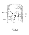
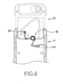
- the multiple torsion spring 30 has opposite ends 310 and 320, between which the multiple torsion spring 30 is formed in a zigzag shape and includes at least three coil spring sections 330, 332 and 334.
- the multiple torsion spring 30 is configured in a "W" shape.
- the coil spring sections are positioned between the opposite ends 310 and 320, wherein one of the opposite ends is a fixed end 310 and the other is a moving end 320.
- the coil spring sections include a first coil spring section 330, a central coil spring section 332 connected to the first coil section 330 and wound spirally at least two turns, and a second coil spring section 334 connected to the central coil spring section 332 and positioned symmetrically to the first coil spring section 330 about the central coil spring section 332.
- the first and second coil spring sections 330 and 334 exert expanding elastic force in the direction rendering them to be spaced away from each other
- the central coil spring section 332 exerts expanding elastic force in the direction rendering the opposite ends 310 and 320 to be spaced away from each other.
- the multiple torsion spring 30 serves as a driving power source for a sliding-type portable communication terminal for providing force to close the communication terminal in a section within a predetermined distance and providing force to open the communication terminal in a section beyond the predetermined distance.
- the section within the predetermined distance means a section where compulsory force is provided by a user
- the section beyond the predetermined distance means a section where driving force is provided by the multiple torsion spring.
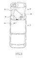
- the inventive semi-automatic sliding device includes a top surface 101 of a main housing 10 and a bottom surface 201 of a sliding housing 20, the semi-automatic sliding device being provided so as to close or open the sliding housing 20 in relation to the main housing 10.
- the top surface 101 may be formed integrally with the main housing 10 by a fabrication process such as injection molding, or formed separately from the main housing 10 and assembled to the main housing 10.
- the bottom surface 201 may be formed integrally with the sliding housing 20, or formed separately from the sliding housing 20 and assembled to the sliding housing 20.
- a pair of guide rails 110 are formed at the opposite side edges on the top surface 101, so that the opposite side edges 202 of the bottom surface 201 are fitted to the guide rails 110, thereby being guided along the guide rails 110.
- the semi-automatic sliding device provides force to close the sliding housing 20 when the sliding housing 20 is positioned in a section within a predetermined distance from the main housing 10, and provides force to open the sliding housing 20 when the sliding housing 20 is positioned in a section beyond the predetermined distance.
- the section within the predetermined distance means a section where compulsory force is provided by a user
- the section beyond the predetermined distance means a section where driving force is provided by the multiple torsion spring 30.
- the semi-automatic sliding device is configured by the top surface 101, the bottom surface 201, and the multiple torsion spring 30, wherein the torsion spring 30 includes said fixed end 310 rotatably attached to the top surface 101 of the main housing 10 at a predetermined location, and said moving end 320 rotatably attached to the bottom surface 201 and moving with the sliding housing 20.
- the multiple torsion spring 30 has the opposite ends 310 and 320, between which the multiple torsion spring 30 is formed in a zigzag shape and includes the at least three coil spring sections 330, 332 and 334.
- the multiple torsion spring 30 is configured in a "W" shape.
- the coil spring sections are positioned between the opposite ends 310 and 320 and include first coil spring section 330, central coil spring section 332 connected to the first coil section 330 and wound spirally at least two turns, and second coil spring section 334 connected to the central coil spring section 332 and positioned in symmetry to the first coil spring section 330 about the central coil spring section 332.
- the first and second coil spring sections 330 and 334 exert expanding elastic force in the direction rendering them to be spaced away from each other
- the central coil spring section 332 exerts expanding elastic force in the direction rendering the opposite ends 310 and 320 to be spaced away from each other.
- Each of the first and second coil spring sections 330 and 334 is formed by being wound one turn, and the central coil spring 332 is wound at least two turns, preferably three turns.
- the turns of the coil spring 332 are not formed in the same diameter, but formed in such a manner that the diameters thereof are reduced when approaching the center of the coil spring 332, whereby the coil spring 332 can be formed in a slim configuration.
- each of the fixed end 310 and the moving end 320 of the multiple torsion spring is provided with a fastener such as a rivet, so that the fixed end 310 can be attached to the top surface 101 by anchoring the rivet at the bottom surface of the main housing 10, and the moving end 320 can be attached to the bottom surface 201 by anchoring the rivet at the top surface of the sliding housing 20, wherein the rivets are engaged with the fixed and moving ends 310 and 320, respectively, by being formed through a fabrication process such as insert-injection molding.
- a fastener such as a rivet
- the multiple torsion spring moves with the sliding housing until the sliding housing is moved by a predetermined distance.
- the first and second coil spring sections and the central coil spring section are adapted to move along predetermined tracks, respectively. If the sliding housing moves beyond the predetermined distance, the sliding housing is automatically moved to the final position by the elastic force of the multiple torsion spring.
- the present invention provides a multiple torsion spring which is advantageous for sliming a portable communication terminal.
- the inventive multiple torsion spring has three coil spring sections arranged in a zigzag pattern, the deformation of the torsion spring can be maximized, and the elastic force exerted by the torsion spring can be increased.
- the inventive torsion spring is configured in such a manner that the three coil spring sections move along predetermined tracks, respectively. As a result, it is possible to remove a dead section or a dead point while the sliding housing is being slid. Furthermore, according to the present invention, the distances from the central coil spring section to the first and to the second coil spring sections are reduced.
Landscapes
- Engineering & Computer Science (AREA)
- Signal Processing (AREA)
- Computer Networks & Wireless Communication (AREA)
- Telephone Set Structure (AREA)
Applications Claiming Priority (1)
| Application Number | Priority Date | Filing Date | Title |
|---|---|---|---|
| KR1020060101074A KR100827112B1 (ko) | 2006-10-17 | 2006-10-17 | 다중 토션 스프링 및 이를 채용한 반자동 슬라이딩 장치 |
Publications (1)
| Publication Number | Publication Date |
|---|---|
| EP1914963A1 true EP1914963A1 (fr) | 2008-04-23 |
Family
ID=38961903
Family Applications (1)
| Application Number | Title | Priority Date | Filing Date |
|---|---|---|---|
| EP07118678A Withdrawn EP1914963A1 (fr) | 2006-10-17 | 2007-10-17 | Ressort à torsions multiples et dispositif coulissant semi-automatique l'utilisant |
Country Status (4)
| Country | Link |
|---|---|
| US (1) | US7945299B2 (fr) |
| EP (1) | EP1914963A1 (fr) |
| KR (1) | KR100827112B1 (fr) |
| CN (1) | CN101166203B (fr) |
Families Citing this family (8)
| Publication number | Priority date | Publication date | Assignee | Title |
|---|---|---|---|---|
| EP1936925B1 (fr) * | 2006-12-21 | 2011-08-31 | Sharp Kabushiki Kaisha | Ressort à enroulement de torsion et terminal mobile coulissant équipé avec |
| JP4341925B2 (ja) * | 2007-05-11 | 2009-10-14 | 株式会社ストロベリーコーポレーション | スライド装置並びにスライド装置を用いた電子機器 |
| TWM348430U (en) * | 2008-05-28 | 2009-01-01 | Micro Star Int Co Ltd | Sliding-type mechanism with a semi-automatic opening function |
| KR101006882B1 (ko) * | 2008-09-03 | 2011-01-12 | 주식회사 엔티에스 | 반자동 스프링 |
| TW201023598A (en) * | 2008-12-12 | 2010-06-16 | Asustek Comp Inc | Electronic device |
| KR101104953B1 (ko) * | 2010-01-26 | 2012-01-12 | 주식회사 다이아벨 | 스프링모듈 및 이를 구비하는 슬라이드 장치 |
| CN103347374A (zh) * | 2013-06-28 | 2013-10-09 | 谢虹 | 美容喷雾器 |
| CN207926664U (zh) * | 2018-02-09 | 2018-09-28 | 广东欧珀移动通信有限公司 | 移动终端 |
Citations (8)
| Publication number | Priority date | Publication date | Assignee | Title |
|---|---|---|---|---|
| EP1150476A2 (fr) | 2000-04-28 | 2001-10-31 | Nokia Mobile Phones Ltd. | Structure télescopique pour un appareil téléphonique |
| JP2004253526A (ja) | 2003-02-19 | 2004-09-09 | Strawberry Corporation | スライド装置並びにスライド装置を用いた電子機器 |
| JP2005159633A (ja) | 2003-11-25 | 2005-06-16 | Sugatsune Ind Co Ltd | 携帯電子機器 |
| KR100516220B1 (ko) | 2005-03-09 | 2005-09-26 | 최용길 | 휴대폰용 슬라이드 조립체 |
| JP2006050204A (ja) | 2004-08-04 | 2006-02-16 | Advanex Inc | スライドユニット及び携帯製品 |
| WO2006031078A1 (fr) | 2004-09-15 | 2006-03-23 | M2Sys Co., Ltd | Mecanisme coulissant servant a ouvrir et fermer un telephone cellulaire |
| US20060178176A1 (en) * | 2005-02-04 | 2006-08-10 | Samsung Electronics Co., Ltd. | Terminal |
| US20060180457A1 (en) | 2005-02-01 | 2006-08-17 | Young-Soo Han | Sliding mechanism for use with portable electronic device and method of operating the same |
Family Cites Families (10)
| Publication number | Priority date | Publication date | Assignee | Title |
|---|---|---|---|---|
| KR20050019808A (ko) | 2002-06-28 | 2005-03-03 | 아방티 파르마 소시에테 아노님 | 스트렙토마이세스 속 세균의 PapM 폴리펩타이드의신규 변이체 |
| EP1661257A1 (fr) * | 2003-08-25 | 2006-05-31 | M2SYS Co., Ltd. | Dispositif d'ouverture / de fermeture coulissant et terminal portable muni de ce dispositif |
| BRPI0507769A (pt) * | 2004-02-10 | 2007-09-04 | Lee Han Sang | mecanismo de movimemnto e instrumento integrado com o mesmo |
| KR200365340Y1 (ko) | 2004-07-13 | 2004-10-20 | 주식회사 대성텔레콤 | 휴대용 단말기의 반자동 슬라이드 힌지구조 |
| KR200365393Y1 (ko) | 2004-07-20 | 2004-10-22 | 주식회사 대성텔레콤 | 휴대용 단말기의 슬라이드 힌지구조 |
| KR200403708Y1 (ko) | 2005-04-19 | 2005-12-12 | 도옥균 | 휴대 무선단말기의 탄력 슬라이딩용 스프링 |
| KR200416094Y1 (ko) | 2006-02-24 | 2006-05-10 | 이근주 | 이동통신 단말기의 슬라이드장치 |
| KR200419120Y1 (ko) | 2006-03-10 | 2006-06-15 | 케이. 에이. 이 (주) | 이동통신 단말기용 슬라이드 모듈 |
| KR100661462B1 (ko) * | 2006-03-28 | 2006-12-27 | 주식회사 엠솔버 | 휴대폰용 슬라이딩 장치 |
| US7583989B2 (en) * | 2006-04-18 | 2009-09-01 | Cheng Uei Precision Industry Co., Ltd. | Sliding-type hinge |
-
2006
- 2006-10-17 KR KR1020060101074A patent/KR100827112B1/ko not_active Expired - Fee Related
-
2007
- 2007-10-11 US US11/870,870 patent/US7945299B2/en not_active Expired - Fee Related
- 2007-10-16 CN CN2007101802705A patent/CN101166203B/zh not_active Expired - Fee Related
- 2007-10-17 EP EP07118678A patent/EP1914963A1/fr not_active Withdrawn
Patent Citations (8)
| Publication number | Priority date | Publication date | Assignee | Title |
|---|---|---|---|---|
| EP1150476A2 (fr) | 2000-04-28 | 2001-10-31 | Nokia Mobile Phones Ltd. | Structure télescopique pour un appareil téléphonique |
| JP2004253526A (ja) | 2003-02-19 | 2004-09-09 | Strawberry Corporation | スライド装置並びにスライド装置を用いた電子機器 |
| JP2005159633A (ja) | 2003-11-25 | 2005-06-16 | Sugatsune Ind Co Ltd | 携帯電子機器 |
| JP2006050204A (ja) | 2004-08-04 | 2006-02-16 | Advanex Inc | スライドユニット及び携帯製品 |
| WO2006031078A1 (fr) | 2004-09-15 | 2006-03-23 | M2Sys Co., Ltd | Mecanisme coulissant servant a ouvrir et fermer un telephone cellulaire |
| US20060180457A1 (en) | 2005-02-01 | 2006-08-17 | Young-Soo Han | Sliding mechanism for use with portable electronic device and method of operating the same |
| US20060178176A1 (en) * | 2005-02-04 | 2006-08-10 | Samsung Electronics Co., Ltd. | Terminal |
| KR100516220B1 (ko) | 2005-03-09 | 2005-09-26 | 최용길 | 휴대폰용 슬라이드 조립체 |
Also Published As
| Publication number | Publication date |
|---|---|
| KR100827112B1 (ko) | 2008-05-02 |
| US7945299B2 (en) | 2011-05-17 |
| CN101166203B (zh) | 2011-01-12 |
| KR20080034742A (ko) | 2008-04-22 |
| CN101166203A (zh) | 2008-04-23 |
| US20080089036A1 (en) | 2008-04-17 |
Similar Documents
| Publication | Publication Date | Title |
|---|---|---|
| US7945299B2 (en) | Multiple torsion spring and semi-automatic sliding device using the same | |
| KR100689410B1 (ko) | 슬라이딩 타입 휴대 단말기의 반 자동 슬라이딩 장치 | |
| EP1906631B1 (fr) | Dispositif coulissant semi-automatique pour terminal portable et terminal portable l'utilisant | |
| US7184806B2 (en) | Sliding module for mobile terminal | |
| EP1919171B1 (fr) | Ressort, dispositif coulissant semi-automatique l'utilisant et terminal de communication portable de type coulissant | |
| KR100605862B1 (ko) | 슬라이딩 타입 무선 단말기 | |
| CN100366135C (zh) | 用于滑盖式便携式终端的弹簧组件 | |
| EP2034700A1 (fr) | Terminal de communication mobile de type coulissant | |
| US20100071159A1 (en) | Hinge type cover opening and closing device for mobile phone | |
| EP1879362B1 (fr) | Terminal portable coulissant | |
| US7450979B2 (en) | Sliding module for portable terminal | |
| EP1921830B1 (fr) | Biellette et terminal portable de type coulissant l'incorporant | |
| KR100848858B1 (ko) | 좁은 궤적을 갖는 탄성 모듈 및 이를 구비한 슬라이딩 타입휴대폰의 슬라이드 장치 | |
| KR100800712B1 (ko) | 스윙 타입 이동 통신 단말기의 반자동 스윙 장치 | |
| KR100689433B1 (ko) | 슬라이딩 겸용 폴딩 타입 휴대용 디지털 통신 장치 및그의 힌지 장치 | |
| KR100785368B1 (ko) | 휴대폰용 다단 슬라이드 힌지 모듈 | |
| KR100834647B1 (ko) | 슬라이딩 타입 이동 통신 단말기 및 그의 반자동 슬라이딩장치 | |
| KR20100047117A (ko) | 스프링 모듈을 구비하는 휴대용 단말기 | |
| CN201001134Y (zh) | 一种手机 | |
| KR101110448B1 (ko) | 폴더 타입 및 바 타입 겸용 휴대 단말기의 힌지 장치 | |
| KR20060034357A (ko) | 휴대 단말기의 슬라이딩 장치 | |
| KR101639078B1 (ko) | 휴대용 통신 장치의 거치 장치 | |
| EP2280526B1 (fr) | Terminal portable comportant un module à ressort | |
| KR20080022011A (ko) | 슬라이딩 타입 휴대용 단말기의 슬라이딩 모듈 | |
| KR20110001655U (ko) | 휴대폰용 슬라이드 힌지 모듈 |
Legal Events
| Date | Code | Title | Description |
|---|---|---|---|
| PUAI | Public reference made under article 153(3) epc to a published international application that has entered the european phase |
Free format text: ORIGINAL CODE: 0009012 |
|
| 17P | Request for examination filed |
Effective date: 20071017 |
|
| AK | Designated contracting states |
Kind code of ref document: A1 Designated state(s): AT BE BG CH CY CZ DE DK EE ES FI FR GB GR HU IE IS IT LI LT LU LV MC MT NL PL PT RO SE SI SK TR |
|
| AX | Request for extension of the european patent |
Extension state: AL BA HR MK RS |
|
| 17Q | First examination report despatched |
Effective date: 20080619 |
|
| AKX | Designation fees paid |
Designated state(s): DE FR GB |
|
| RAP1 | Party data changed (applicant data changed or rights of an application transferred) |
Owner name: SAMSUNG ELECTRONICS CO., LTD. |
|
| STAA | Information on the status of an ep patent application or granted ep patent |
Free format text: STATUS: THE APPLICATION IS DEEMED TO BE WITHDRAWN |
|
| 18D | Application deemed to be withdrawn |
Effective date: 20161020 |