EP1915033A2 - Système et procédé pour effectuer le remplissage sélectif pour une coquille d'aide auditive - Google Patents
Système et procédé pour effectuer le remplissage sélectif pour une coquille d'aide auditive Download PDFInfo
- Publication number
- EP1915033A2 EP1915033A2 EP07118785A EP07118785A EP1915033A2 EP 1915033 A2 EP1915033 A2 EP 1915033A2 EP 07118785 A EP07118785 A EP 07118785A EP 07118785 A EP07118785 A EP 07118785A EP 1915033 A2 EP1915033 A2 EP 1915033A2
- Authority
- EP
- European Patent Office
- Prior art keywords
- fill
- shell
- fill region
- region
- display
- Prior art date
- Legal status (The legal status is an assumption and is not a legal conclusion. Google has not performed a legal analysis and makes no representation as to the accuracy of the status listed.)
- Withdrawn
Links
Images



Classifications
-
- H—ELECTRICITY
- H04—ELECTRIC COMMUNICATION TECHNIQUE
- H04R—LOUDSPEAKERS, MICROPHONES, GRAMOPHONE PICK-UPS OR LIKE ACOUSTIC ELECTROMECHANICAL TRANSDUCERS; ELECTRIC HEARING AIDS; PUBLIC ADDRESS SYSTEMS
- H04R25/00—Electric hearing aids
- H04R25/65—Housing parts, e.g. shells, tips or moulds, or their manufacture
- H04R25/658—Manufacture of housing parts
-
- H—ELECTRICITY
- H04—ELECTRIC COMMUNICATION TECHNIQUE
- H04R—LOUDSPEAKERS, MICROPHONES, GRAMOPHONE PICK-UPS OR LIKE ACOUSTIC ELECTROMECHANICAL TRANSDUCERS; ELECTRIC HEARING AIDS; PUBLIC ADDRESS SYSTEMS
- H04R2225/00—Details of deaf aids covered by H04R25/00, not provided for in any of its subgroups
- H04R2225/77—Design aspects, e.g. CAD, of hearing aid tips, moulds or housings
Definitions
- the present invention is directed to a system and method for performing a selective fill for a hearing aid shell.
- a system and method are provided in which a 3D Shell Modeling and Detailing application provides protocols for invoking a simplified mechanism for defining the parts of a hearing aid shell that are filled.
- a simple method is given for providing a filling of the parts of the shell in order to take advantage of the electro-acoustic effect that will help to reduce feedback.
- selective filling also enhances possibilities for manual modification at the point of sale because extra material can be safely removed from the shell in the places where selective fill was applied without physically damaging the instrument.
- the actual physical impression is scanned by 3D scanners to create a pointcloud; pointcloud A set of 3D coordinates defining a 3D shape.
- Pointcloud files that come from 3D scanners are usually in ASCII format; work order An entry in DWOM that contains all information relevant for modelling a shell (or shells in case of binaural order) for the specific order of the ITE hearing instrument.
- Figure 1A provides an overview of the process flow 100 according to an embodiment of the invention
- Figure 1 B provides an overview of the system 50 according to an embodiment of the invention.
- the system 50 and process 100 may all be implemented by standard computer components that include a processor 90, a display 60, and user input devices 70.
- the processor 90 could be a networked desktop or laptop PC
- the display 60 could be a traditional monitor
- the input devices 70 could include a keyboard, mouse, and the like.
- the various embodiments discussed below are advantageous in that they provide very simple, quick, and straightforward mechanisms for implementing the various described functions of the system.
- a user loads 110 a work order 82 stored in a database 80 for a particular user's shell into the computer system.
- the shell definition 84 which is defined by data representing a three-dimensional shape, is presented 62 on the display 60 to the user.
- the user invokes 120 a software fill process 92 that is used to specify fill regions 14 of the shell.
- this routine 92 is invoked, in a preferred embodiment, the shell that is displayed 62 can be rendered transparent or transluscent.
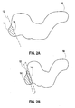
- the user identifies the desired fill region 14 of the shell 130.
- a boundary plane 12 in order to define 140 a boundary plane 12, the user moves a mouse 70 outside of the displayed shell 10 and draws a line (plane) 12 (e.g., by clicking and dragging the mouse 70, by separately clicking on two endpoints, or specifying the line or endpoints in some other known manner using the user input devices) respresentative of a plane having an axis in a direction perpendicular to the display 60 and having another perpendicular axis going through the displayed shell 10.
- a portion 14 of the shell that is bounded by the plane 12 is shaded or colored with some indicia that indicates it is the defined fill region. This could be done by the use of a color, degree of transparency, or any other form of distinguishing the fill portion of the shell 10 from the non-fill portion. By default, the smallest part of the two regions bounded by the plane 12 would be selected as the fill region 14.
- the three-dimensional model of the shell 10 may be rotated on the display with the user interface of the computer so that the selected fill region can be better displayed.
- the line 12 that was originally formed becomes a plane
- the linear intersection line becomes an ellipse or other shape 16 defined by the intersection of the plane 12 and the shell 10 as specified by the user.
- the fill region 14 can either default to the smaller of the split shell regions, or the user can be required to select the region 150. In either case, however, the non-selected region can be chosen, e.g., by clicking the mouse 70 over the non-selected region, as the selected region by the user via the user interface, if desired.
- the user can repeat the steps described above to specify the new position of the filled area 14.
- the user interface can be designed so that the drawing of a further line 12 removes the region selected by the drawing of a previous line 12.
- the user can provide some confirmation 170, via the user interface, indicating that this is the actual desired fill region 14. For example, the user can click a "Fill" button 68 presented on the display 60. This provides an indication to the software 92 that the indicated region 14 should be the fill region, and this fill region is identified by data on the system representative of the three-dimensional fill region. Although any form of such an indication could be provided, a one-mouse-button click provides, in a preferred embodiment, a very simple and easy mechanism for performing this function.
- the software may comprise a routine 93 that ensures all surfaces forming the internal shape of the shell are removed in the area where filling is applied. These surfaces include all surfaces in the region 14 except outer shell surface, inner venting channel surface and the selective fill plane.
- the fill plane(s) 12 located on the logical continuation of the line can be ignored.
- This process could be repeated to define multiple fill regions 14 for the shell 10, and the multiple fill regions 14 so defined could either be displayed simultaneously or individually.
- a selectable display option could be provided so that the current, all, or some (defined by a user selection) of the fill regions are displayed.
- the fill boundary can take on more complex shapes, e.g., spheres, ellipsoids, or any other three-dimensional surface shapes.
- Standard computer aided drafting (CAD) techniques could be used to define more complex boundary shapes.
- a reset function can be provided, e.g., by way of a reset button 66, so that any or all of the selective fill regions 14 defined can be removed.
- the selective fill routines 100 should be able to take into account some critical parts of the inner shell topology of the shell and avoid applying selective fill operations, which could damage the critical parts of the inner shell topology.
- These critical parts of the inner shell topology can be for example any kind of suspension systems integrated into the shell.
- the software has a mechanism 64 for alerting the user that the fill region 14 may need to be modified.
- a "traffic light” display element 64 having, e.g., red, yellow, and green light elements.
- a red light would indicate that the shell shape has been modified and that the selective fill process should be performed again to accommodate any changes affecting the fill region 14.
- a status bar 63 could provide some explanatory text, such as, "Changes in the previous functions have invalidated the Selective Fills.
- the traffic light element 64 can be added to a procedure dialog or toolbar of the display 90 or elsewhere. After each (re-)selection of the area selected to be filled, the traffic light 64 should show whether this selection is allowed.
- Various other rules 95 may be utilized in the software for ensuring that only permissible fills are implemented. For example, if the area selected for filling contains the receiver hole, then the "Fill" button 68 should be disabled, and an explanatory message can be provided in the status bar 63. If the area selected for filling 14 contains the complete opening of the shell, then the "Fill” button 68 should be disabled, and an explanatory message can be provided in the status bar 63. If the tip of the shell contains any openinings in addition to the standard opening on the bottom of the shell and the area selected for the filling 14 contains any part of the opening(s) on the tip of the shell, the "Fill” button 68 should be disabled, and an explanatory message can be provided in the status bar 63.
- the plane 13 which defines the bottom of the shell 10
- the plane 13 can be used for closing the selective fill plane contour 16 and for the filling operation as the additional boundary of the filled part 14. This case can happen in the case where a non-semi-modular shell is built, as illustrated by Figure 3A.
- the selective fill For a semi-modular cell, as illustrated in Figure 3B, if the area for filling 14 is selected and the selective fill plane 12 intersects the faceplate 18 geometry, then the "Fill" button 68 should be disabled, and an explanatory message can be provided in the status bar 63.
- This design does not allow use of the cutting plane 12 for the selective fill operation.
- the selective fill either has the shell material everywhere except the selective fill plane 12 itself, or if it does not (like in the case when selective fill plane intersects faceplate, as illustrated), then fill should not be allowed.
- the "Fill" button 68 could be disabled, and an explanatory message can be provided in the status bar 63.
- preferences on how the final fill region should be can be provided in the software via, e.g., a configuration edit dialog or preferences table 86.
- a selective filling color or degree of transparency for rendering the part 14 of the shell 10 selected for filling may be specified in preferences 86.
- the preferences table 86 can also indicate whether the Receiver, Faceplate, Electronics, and Wireless Coil are rendered in the display 60 or not by default, and it is also possible to indicate in the preferences table 86 whether a Grid is rendered on the display 60 by default in the procedure 92.
- a feature recognition routine 96 such as that disclosed in U.S. Application Serial Number 11/347,151 , herein incorporated by reference, may be used to automatically or assist in identifying the shell fillable areas such as helix, canal, anti-tragus, and to automatically fill these area on the device basis.
- the present invention may be described in terms of functional block components and various processing steps. Such functional blocks may be realized by any number of hardware and/or software components configured to perform the specified functions.
- the present invention may employ various integrated circuit components, e.g., memory elements, processing elements, logic elements, look-up tables, and the like, which may carry out a variety of functions under the control of one or more microprocessors or other control devices.
- the elements of the present invention are implemented using software programming or software elements the invention may be implemented with any programming or scripting language such as C, C++, Java, assembler, or the like, with the various algorithms being implemented with any combination of data structures, objects, processes, routines or other programming elements.
- the present invention could employ any number of conventional techniques for electronics configuration, signal processing and/or control, data processing and the like.
Landscapes
- Engineering & Computer Science (AREA)
- Manufacturing & Machinery (AREA)
- Health & Medical Sciences (AREA)
- General Health & Medical Sciences (AREA)
- Neurosurgery (AREA)
- Otolaryngology (AREA)
- Physics & Mathematics (AREA)
- Acoustics & Sound (AREA)
- Signal Processing (AREA)
- Processing Or Creating Images (AREA)
- Stored Programmes (AREA)
- Digital Computer Display Output (AREA)
Applications Claiming Priority (1)
| Application Number | Priority Date | Filing Date | Title |
|---|---|---|---|
| US11/583,593 US7609259B2 (en) | 2006-10-18 | 2006-10-18 | System and method for performing a selective fill for a hearing aid shell |
Publications (2)
| Publication Number | Publication Date |
|---|---|
| EP1915033A2 true EP1915033A2 (fr) | 2008-04-23 |
| EP1915033A3 EP1915033A3 (fr) | 2015-03-11 |
Family
ID=39004805
Family Applications (1)
| Application Number | Title | Priority Date | Filing Date |
|---|---|---|---|
| EP07118785.0A Withdrawn EP1915033A3 (fr) | 2006-10-18 | 2007-10-18 | Système et procédé pour effectuer le remplissage sélectif pour une coquille d'aide auditive |
Country Status (2)
| Country | Link |
|---|---|
| US (1) | US7609259B2 (fr) |
| EP (1) | EP1915033A3 (fr) |
Families Citing this family (6)
| Publication number | Priority date | Publication date | Assignee | Title |
|---|---|---|---|---|
| ES2378060T3 (es) * | 2001-03-02 | 2012-04-04 | 3Shape A/S | Procedimiento para modelar piezas auriculares personalizadas |
| US8554352B2 (en) * | 2009-05-07 | 2013-10-08 | Siemens Hearing Instruments, Inc. | Method of generating an optimized venting channel in a hearing instrument |
| JP5330090B2 (ja) * | 2009-05-20 | 2013-10-30 | キヤノン株式会社 | 放射線撮影装置、その表示処理方法、及びプログラム |
| US10158954B1 (en) * | 2017-12-17 | 2018-12-18 | Chester Zbigniew Pirzanski | Template based custom ear insert virtual shaping method |
| US10325418B1 (en) | 2018-11-15 | 2019-06-18 | Chester Zbigniew Pirzanski | 3D virtual automated modeling of custom posterior concha module |
| WO2020102722A1 (fr) * | 2018-11-16 | 2020-05-22 | Starkey Laboratories, Inc. | Modélisation de coque de dispositif à porter sur l'oreille |
Family Cites Families (5)
| Publication number | Priority date | Publication date | Assignee | Title |
|---|---|---|---|---|
| US6533062B1 (en) * | 2000-09-25 | 2003-03-18 | Phonak Ag | Production process for custom-moulded ear-plug devices |
| ES2378060T3 (es) * | 2001-03-02 | 2012-04-04 | 3Shape A/S | Procedimiento para modelar piezas auriculares personalizadas |
| EP1246506A1 (fr) * | 2001-03-26 | 2002-10-02 | Widex A/S | Système CAD-CAM pour préparer une prothèse auditive |
| DK1574111T3 (en) * | 2002-12-19 | 2017-10-02 | Siemens Corp | Automatic binaural ear shell modulation for hearing aids |
| US7308328B2 (en) * | 2003-05-15 | 2007-12-11 | Siemens Medical Solutions Usa, Inc. | Synchronized processing of ear shells for hearing aids |
-
2006
- 2006-10-18 US US11/583,593 patent/US7609259B2/en not_active Expired - Fee Related
-
2007
- 2007-10-18 EP EP07118785.0A patent/EP1915033A3/fr not_active Withdrawn
Also Published As
| Publication number | Publication date |
|---|---|
| EP1915033A3 (fr) | 2015-03-11 |
| US7609259B2 (en) | 2009-10-27 |
| US20080094392A1 (en) | 2008-04-24 |
Similar Documents
| Publication | Publication Date | Title |
|---|---|---|
| EP1915033A2 (fr) | Système et procédé pour effectuer le remplissage sélectif pour une coquille d'aide auditive | |
| US20020175948A1 (en) | Graphical user interface method and apparatus for interaction with finite element analysis applications | |
| US11556234B2 (en) | WYSIWYG editor for creating and editing a feature control frame for geometric dimensioning and tolerancing in computer-aided design system | |
| EP3711016B1 (fr) | Systèmes et procédés de segmentation d'images | |
| JP3647407B2 (ja) | 画像処理装置 | |
| CN112819741B (zh) | 一种图像融合方法、装置,电子设备及存储介质 | |
| US7103527B2 (en) | Negotiated interconnection of visual modeling elements | |
| CN112784330A (zh) | 一种基于ibim的多源图形处理方法 | |
| CN104991707A (zh) | 一种显示用户界面方法及装置 | |
| US12242774B2 (en) | Predictive modeling | |
| CN102177518B (zh) | 实现有限元模型的方法和设备 | |
| EP2410487B1 (fr) | Procédé pour modifier automatiquement une fonction graphique de sorte qu'elle se conforme à une limite de résolution | |
| EP1091325B1 (fr) | Paramètres définissables par l'utilisateur servant pour le calcul d'analyse d'éléments finis dans un programme CAD | |
| CN115131500A (zh) | 图像标注方法、装置、可读存储介质及电子设备 | |
| KR102833329B1 (ko) | 이미지의 전경 및 배경을 분리하는 방법 및 장치 | |
| US20030107602A1 (en) | Display system and display method that renders construction view of an object, and recording media thereof | |
| CN112328234A (zh) | 图像处理方法及装置 | |
| CN113436330A (zh) | 面积对象的生成方法、装置、电子设备及可读存储介质 | |
| JP2005327192A (ja) | ハードウエア設計システムおよびその方法 | |
| JP7651400B2 (ja) | 設計支援装置、制御方法、及びプログラム | |
| JP2025124592A (ja) | コンピュータ支援設計三次元モデルのトリミングされた表現の生成 | |
| CN108392270A (zh) | 医用接骨板数字化定制的方法 | |
| US20240062458A1 (en) | Information processing system, information processing method, and non-transitory computer readable medium | |
| CN113220375B (zh) | 基于Allegro软件生成镂空文丝印的方法及系统 | |
| JP2000048218A (ja) | コンピュータ支援設計装置及びコンピュータ支援設計方法並びにコンピュータ支援設計プログラムを記録した記録媒体 |
Legal Events
| Date | Code | Title | Description |
|---|---|---|---|
| PUAI | Public reference made under article 153(3) epc to a published international application that has entered the european phase |
Free format text: ORIGINAL CODE: 0009012 |
|
| AK | Designated contracting states |
Kind code of ref document: A2 Designated state(s): AT BE BG CH CY CZ DE DK EE ES FI FR GB GR HU IE IS IT LI LT LU LV MC MT NL PL PT RO SE SI SK TR |
|
| AX | Request for extension of the european patent |
Extension state: AL BA HR MK RS |
|
| PUAL | Search report despatched |
Free format text: ORIGINAL CODE: 0009013 |
|
| AK | Designated contracting states |
Kind code of ref document: A3 Designated state(s): AT BE BG CH CY CZ DE DK EE ES FI FR GB GR HU IE IS IT LI LT LU LV MC MT NL PL PT RO SE SI SK TR |
|
| AX | Request for extension of the european patent |
Extension state: AL BA HR MK RS |
|
| RIC1 | Information provided on ipc code assigned before grant |
Ipc: H04R 25/00 20060101AFI20150130BHEP |
|
| RAP1 | Party data changed (applicant data changed or rights of an application transferred) |
Owner name: SIVANTOS GMBH |
|
| AKY | No designation fees paid | ||
| AXX | Extension fees paid |
Extension state: AL Extension state: RS Extension state: BA Extension state: MK Extension state: HR |
|
| REG | Reference to a national code |
Ref country code: DE Ref legal event code: R108 |
|
| STAA | Information on the status of an ep patent application or granted ep patent |
Free format text: STATUS: THE APPLICATION IS DEEMED TO BE WITHDRAWN |
|
| 18D | Application deemed to be withdrawn |
Effective date: 20150912 |