EP1915083B1 - Dispositif de collecte de poussière pour aspirateur - Google Patents
Dispositif de collecte de poussière pour aspirateur Download PDFInfo
- Publication number
- EP1915083B1 EP1915083B1 EP05780568.1A EP05780568A EP1915083B1 EP 1915083 B1 EP1915083 B1 EP 1915083B1 EP 05780568 A EP05780568 A EP 05780568A EP 1915083 B1 EP1915083 B1 EP 1915083B1
- Authority
- EP
- European Patent Office
- Prior art keywords
- dust
- cyclones
- dust collecting
- collecting device
- primary
- Prior art date
- Legal status (The legal status is an assumption and is not a legal conclusion. Google has not performed a legal analysis and makes no representation as to the accuracy of the status listed.)
- Expired - Lifetime
Links
Images




Classifications
-
- A—HUMAN NECESSITIES
- A47—FURNITURE; DOMESTIC ARTICLES OR APPLIANCES; COFFEE MILLS; SPICE MILLS; SUCTION CLEANERS IN GENERAL
- A47L—DOMESTIC WASHING OR CLEANING; SUCTION CLEANERS IN GENERAL
- A47L9/00—Details or accessories of suction cleaners, e.g. mechanical means for controlling the suction or for effecting pulsating action; Storing devices specially adapted to suction cleaners or parts thereof; Carrying-vehicles specially adapted for suction cleaners
- A47L9/10—Filters; Dust separators; Dust removal; Automatic exchange of filters
- A47L9/16—Arrangement or disposition of cyclones or other devices with centrifugal action
-
- A—HUMAN NECESSITIES
- A47—FURNITURE; DOMESTIC ARTICLES OR APPLIANCES; COFFEE MILLS; SPICE MILLS; SUCTION CLEANERS IN GENERAL
- A47L—DOMESTIC WASHING OR CLEANING; SUCTION CLEANERS IN GENERAL
- A47L9/00—Details or accessories of suction cleaners, e.g. mechanical means for controlling the suction or for effecting pulsating action; Storing devices specially adapted to suction cleaners or parts thereof; Carrying-vehicles specially adapted for suction cleaners
- A47L9/10—Filters; Dust separators; Dust removal; Automatic exchange of filters
- A47L9/16—Arrangement or disposition of cyclones or other devices with centrifugal action
- A47L9/165—Construction of inlets
-
- A—HUMAN NECESSITIES
- A47—FURNITURE; DOMESTIC ARTICLES OR APPLIANCES; COFFEE MILLS; SPICE MILLS; SUCTION CLEANERS IN GENERAL
- A47L—DOMESTIC WASHING OR CLEANING; SUCTION CLEANERS IN GENERAL
- A47L9/00—Details or accessories of suction cleaners, e.g. mechanical means for controlling the suction or for effecting pulsating action; Storing devices specially adapted to suction cleaners or parts thereof; Carrying-vehicles specially adapted for suction cleaners
- A47L9/10—Filters; Dust separators; Dust removal; Automatic exchange of filters
- A47L9/16—Arrangement or disposition of cyclones or other devices with centrifugal action
- A47L9/1608—Cyclonic chamber constructions
-
- A—HUMAN NECESSITIES
- A47—FURNITURE; DOMESTIC ARTICLES OR APPLIANCES; COFFEE MILLS; SPICE MILLS; SUCTION CLEANERS IN GENERAL
- A47L—DOMESTIC WASHING OR CLEANING; SUCTION CLEANERS IN GENERAL
- A47L9/00—Details or accessories of suction cleaners, e.g. mechanical means for controlling the suction or for effecting pulsating action; Storing devices specially adapted to suction cleaners or parts thereof; Carrying-vehicles specially adapted for suction cleaners
- A47L9/10—Filters; Dust separators; Dust removal; Automatic exchange of filters
- A47L9/16—Arrangement or disposition of cyclones or other devices with centrifugal action
- A47L9/1616—Multiple arrangement thereof
- A47L9/1625—Multiple arrangement thereof for series flow
- A47L9/1633—Concentric cyclones
-
- A—HUMAN NECESSITIES
- A47—FURNITURE; DOMESTIC ARTICLES OR APPLIANCES; COFFEE MILLS; SPICE MILLS; SUCTION CLEANERS IN GENERAL
- A47L—DOMESTIC WASHING OR CLEANING; SUCTION CLEANERS IN GENERAL
- A47L9/00—Details or accessories of suction cleaners, e.g. mechanical means for controlling the suction or for effecting pulsating action; Storing devices specially adapted to suction cleaners or parts thereof; Carrying-vehicles specially adapted for suction cleaners
- A47L9/10—Filters; Dust separators; Dust removal; Automatic exchange of filters
- A47L9/16—Arrangement or disposition of cyclones or other devices with centrifugal action
- A47L9/1616—Multiple arrangement thereof
- A47L9/1641—Multiple arrangement thereof for parallel flow
-
- Y—GENERAL TAGGING OF NEW TECHNOLOGICAL DEVELOPMENTS; GENERAL TAGGING OF CROSS-SECTIONAL TECHNOLOGIES SPANNING OVER SEVERAL SECTIONS OF THE IPC; TECHNICAL SUBJECTS COVERED BY FORMER USPC CROSS-REFERENCE ART COLLECTIONS [XRACs] AND DIGESTS
- Y10—TECHNICAL SUBJECTS COVERED BY FORMER USPC
- Y10S—TECHNICAL SUBJECTS COVERED BY FORMER USPC CROSS-REFERENCE ART COLLECTIONS [XRACs] AND DIGESTS
- Y10S55/00—Gas separation
- Y10S55/03—Vacuum cleaner
Definitions
- the present invention relates to a dust collecting device for a vacuum cleaner, and more particularly, to a dust collecting device for a vacuum cleaner which collects dust by a cyclone principle.
- the cyclone dust collecting device is applied to a vacuum cleaner, for separating foreign matters, such as dust, from circulating air, to collect the dust.
- the cyclone principle utilizes a difference of centrifugal forces for separating foreign matters, such as dust, from air circulating in a spiral.
- the cyclone dust collecting device collecting dust by using the cyclone principle, is generally applied to the vacuum cleaner owing to advantages of the cyclone dust collecting device in that dust collecting performance is good and dust can be removed easily compared to a bag-type dust collecting device in which a dust bag is mounted in an air flow passage for collecting dust.
- a related art dust collecting device for a vacuum cleaner will be described with reference to FIG. 1 .
- the related art dust collecting device is provided with a primary cyclone dust colleting unit 10 for drawing contaminated air containing dust and collecting comparatively large sized particles of the dust therefrom, and a secondary cyclone dust collecting unit 20 on an outside of the primary cyclone dust colleting unit 10 for collecting comparatively small sized particles of the dust.
- the primary cyclone dust collecting unit 10 a cylindrical container having a bottom in close contact with a bottom of the dust collecting device, has a suction pipe 11 in a side surface of an upper portion for introduction of contaminated air containing foreign matters in a tangential direction of an inside wall of the primary cyclone dust collecting unit, and a discharge opening 12 at a center of a top for discharging air cleaned primarily.
- the primary cyclone dust collecting unit 10 has an upper space forming a primary cyclone 13 for separating foreign matters by centrifugal force, and a lower space forming a primary dust storage portion 14 for storing foreign matters separated by the centrifugal force.
- the air from the discharge opening 12 is introduced to the secondary cyclone dust collecting unit 20, and discharged upward after passed through a dust separating step, again.
- the secondary cyclone dust collecting unit 20 includes a plurality of small sized secondary cyclones 21 arranged in a circumferential direction around the upper portion of the primary cyclone dust collecting unit 10, and a secondary dust storage portion 22 for storing dust separated at the secondary cyclone dust collecting unit 21.
- the secondary dust storage portion 22 is under the secondary cyclones 21 around the primary dust storage portion.
- the primary dust storage portion 14 and the secondary dust storage portion 22 are separated by an outside wall of the primary cyclone dust collecting unit 10.
- the related art dust collecting device has a problem in that a dust collecting performance of the primary cyclone dust collecting unit that collects a major portion of the dust is poor because the foreign matters, such as dust, is separated and collected only with single primary cyclone unit.
- the suction pipe is asymmetric, which is extended from one side of the related art dust collecting device toward a center portion thereof, the related art dust collecting device has problems in that the suction pipe is long, air tightness between the cleaner body and the dust collecting device is poor, and a air flow resistance is high due to the bent air flow passage.
- the primary cyclone and the primary dust storage portion are formed as one unit in the cylindrical primary cyclone dust collecting unit having the same upper and lower inside diameters, the dust flies up from the primary dust storage portion toward an upper side of the primary cyclone by the spiral circulation of air in the primary cyclone, thereby leading the dust collecting performance poor.
- the secondary dust storage portion is around the primary dust storage portion, if a capacity of the primary dust storage portion is made greater, a width of the secondary dust storage portion becomes smaller, causing difficulty both in removal of foreign matters from a wall of he secondary dust storage portion, and checking an amount of dust accumulated in the primary dust storage portion due to the secondary dust storage portion that shades the primary dust storage portion.
- EP 1 488 729 describes a vacuum cleaner, in which the waste container-receptacle object of the invention is applicable, is of the type that bases its operation on the so-called cyclone or centrifugal effect, throwing the wastes drawn in against the side walls of the container to produce a depositing of said wastes in the bottom, where they are stored until same is emptied.
- the container comprises two independent tanks wherein most of the side surface and bottom thereof is closed by a tiltable cover, whose opening permits easy and effective emptying and cleaning.
- the tanks have respective inclined partition walls that reduce the amount of particles that rise up to the top area where some filters provided for in a top cover are located. This also permits the acceptable level of wastes to rise above such partition walls.
- GB-A-2362341 describes an upright vacuum cleaner comprising a body having a dust chamber and a motor chamber, a suction brush connected to the body, and a removable dual cyclone-type dust collecting means comprising an upper cover having a first air inlet and an air outlet, a cylindrical outer cyclone receptacle having open ends and being coupled to the upper cover, an inner cyclone receptacle coupled to the upper cover and a removable lower cover to allow removal of collected dust.
- the inner cyclone receptacle may comprise a grille with a plurality of holes and a second air inlet.
- a further cleaner is claimed having a single cyclone dust collecting means.
- An object of the present invention is to provide a dust collecting device for a vacuum cleaner, which has an improved dust collecting performance.
- the dust container is symmetric exterior in a left/right direction.
- the primary cyclones are connected to a suction air guide portion for guiding the air containing dust to the primary cyclones.
- the suction air guide portion is symmetric with respect to a plane of symmetry of the dust container.
- the primary cyclones are in the dust container, and symmetric to each other with respect to the plane of symmetry of the dust container.
- the primary cyclones are provided in the dust container in an up/down direction.
- the suction air guide portion includes a suction pipe having an inlet portion at an upper portion of an outside circumferential surface of the dust container, and a guide wall for guiding the air guided by the suction pipe to insides of the primary cyclones.
- the primary cyclones have first inlets between the guide wall and the suction pipe, respectively.
- the guide wall is opposite to the suction pipe, and has one end, and the other end connected to one side edge of one of the first inlets, and one side edge of the other one of the first inlets respectively, and a middle portion projected toward the suction pipe for splitting the air supplied through the suction pipe in two sides toward the first inlets.
- the primary cyclones have top ends connected to an upper cover openably provided to an upper portion of the dust container.
- the primary cyclones are spaced predetermined heights from a bottom of the dust container.
- the dust collecting device further includes a filter in the dust container for filtering dust from the air from the dust container.
- the filter is on one side of the primary cyclones, such that a portion of the air introduced to the primary cyclones is discharged to an outside of the dust container through the secondary cyclones, and rest of the air is discharged to the outside of the dust container through the filter.
- the dust container forms a bottom of the primary dust collecting chamber for storing dust separated by the primary cyclones, and a bottom of the secondary dust collecting chamber for storing dust separated by the secondary cyclones, and includes an openable bottom.
- the secondary cyclones includes secondary cyclone bodies mounted in the secondary cyclones in an up/down direction respectively, and a spiral circulation forming member in each of the secondary cyclone bodies.
- the spiral circulation forming member includes at least one blade provided to an upper portion of the secondary cyclone body.
- the at least one blade is provided to an outside circumferential surface of an air discharge pipe inserted in the upper portion of the secondary cyclone body for guiding air discharged from the secondary cyclone body.
- the air discharge member has a lower end connected to a top of the secondary cyclone body and a top connected to the top of the dust container.
- the dust container includes secondary dust containers between lower portions of the secondary cyclone bodies and the bottom of the dust container surrounded by an inside circumferential surface of the dust container, for storing dust separated by the secondary cyclone body.
- a canister type vacuum cleaner As one embodiment of a vacuum cleaner having a dust collecting device in accordance with a preferred embodiment of the present invention applied thereto, a canister type vacuum cleaner will be described.
- the vacuum cleaner includes a suction nozzle for drawing air containing foreign matters while moving along a floor to be cleaned a cleaner body provided separate from the suction nozzle, and a connection pipe connected between the suction nozzle and the cleaner body for guiding contaminated air from the suction nozzle to the cleaner body.
- the suction nozzle has a predetermined size of nozzle suction opening in a bottom for drawing dust from the floor by air suction force generated at the cleaner body.
- an electric unit for controlling the vacuum cleaner there are an electric unit for controlling the vacuum cleaner, and a motor-fan assembly for drawing air.
- the cleaner body has a hose connection portion at a front upper center for connecting the connection pipe thereto, wheels rotatably mounted at opposite sides of a rear of the cleaner body for smooth moving of the cleaner body on the floor, and a caster at a front portion of a bottom of the cleaner body, for changing a direction of the cleaner body.
- the cleaner body has the dust collecting device in accordance with a preferred embodiment of the present invention detachably mounted thereto for separating and collecting foreign matters, such as dust.
- Air from the dust collecting device passes a predetermined air discharge passage in the cleaner body, and the motor-fan assembly, and is discharged to an outside of the cleaner body.
- the dust collecting device may be mounted to a rear portion of the cleaner body or a front portion of the cleaner body.
- the cleaner body has a dust collecting device mounting portion at the rear or front portion of the cleaner body for mounting the dust collecting device.
- a suction flow passage passed through an upper portion of the cleaner body in a front/rear direction for guiding the air containing dust to the dust collecting device.
- the dust collecting device 100 in accordance with a preferred embodiment of the present invention will be described with reference to a case the dust collecting device is mounted to the rear portion of the cleaner body.
- the dust collecting device 100 in accordance with a preferred embodiment of the present invention includes a dust container 110 for storing dust, and a cyclone unit 200 in the dust container for separating dust by the cyclone principle.
- the cyclone unit 200 includes primary cyclones, and secondary cyclones, both for separating dust by the cyclone principle.
- the cyclone unit includes two primary cyclones 210, and 220, and two secondary cyclones 250, and 260 arranged in parallel, wherein the two secondary cyclones 250, and 260 are surrounded by the two primary cyclones, respectively.
- the dust container 110 surrounds the primary cyclones 210, and 220 for storing dust separated by the primary cyclones and the secondary cyclones.
- the dust container 110 has a symmetric exterior in a left/right direction.
- the exterior of the dust container 110 i.e., a portion on one side of the plane of symmetry and a portion on the other side of the plane of symmetry form symmetry.
- the plane of symmetry of the dust container 110 is an imaginary plane which is perpendicular to a bottom of the dust container, and divides the exterior of the dust container 110, equally.
- the dust container 110 forms an exterior of the dust collecting device in accordance with a preferred embodiment of the present invention, and it is preferable that a top thereof can be opened.
- the dust container 110 may include a dust container body 111 having an opened top, and an upper cover 112 for opening/closing the top of the dust container body 111.
- the upper cover 112 is openably provided to a top of the dust container 110.
- the upper cover 112 is provided with a air discharge cover (not shown), for collecting the air discharged from the cyclone unit having the dust separated therefrom, and discharging to the discharge flow passage in the cleaner body.
- the secondary cyclones are provided in the primary cyclones respectively, for separating dust from the primary cyclones 250, and 260 respectively by the cyclone principle.
- the two primary cyclones 210, and 220 are connected to a suction air guide portion 230 for guiding the air containing dust to the primary cyclones 210, and 220.
- the suction air guide portion 230 guides the air containing dust from an outside of the dust container 110, more specifically, from a suction flow passage of the cleaner body to an inside of the primary cyclones 210, and 220.
- the suction air guide portion 230 is connected to the suction flow passage which passes a front portion of the cleaner body, specifically, an upper center of the cleaner body, in a front/rear direction.
- suction air guide portion 230 is symmetry with respect to the plane of symmetry of the dust container 110.
- the plane of symmetry of the dust container 110 contains an axis of the suction air guide portion 230. Moreover, inside of the dust container 110 symmetric in a left/right direction, the two primary cyclones 210, and 220 are arranged in symmetry with respect to the plane of symmetry of the dust container 110.
- each of the primary cyclones 210, and 220 is cylindrical provided in the dust container 110 in an up/down direction:
- each of the primary cyclones 210, and 220 is provided in the dust container body 111 such that an axis direction thereof is vertical. Moreover, the primary cyclones are provided at positions spaced a distance from each other.
- the suction air guide portion 230 includes a suction pipe 231 connected to the suction flow passage, and a guide wall 232 for guiding the air guided by the suction pipe 231 to insides of the primary cyclones 210, and 220.
- the suction pipe 231 has an inlet 231 a at an upper outside circumference of the dust container 110, wherein the inlet 231a is at upper center of the exterior of the dust container body 111 when the dust container 110 is seen along the axis of the suction pipe 231.
- Each of the primary cyclones 210, and 220 has a first inlet 211, or 221 at an upper outside circumference between the guide wall 232 and the suction pipe 231, such that the air guided by the guide wall 232 is introduced to the primary cyclones through the first inlets 211, and 221 of the primary cyclones 210, and 220.
- the inlet 231a of the suction pipe is provided to an upper front of the dust container body 111 like the embodiment, the axis of the suction pipe 231 passes through the exterior of the dust container body 111 in a front/rear direction.
- the suction pipe 231 is extended toward the guide wall 232, such that the guide wall 232 is opposite to the suction pipe 231.
- the guide wall 232 has one end, and the other end connected to one side edge of one of the first inlets 211, and 221, and one side edge of the other one of the first inlets 211, and 221 respectively, and a middle portion projected toward the suction pipe 231 for splitting the air supplied through the suction pipe 231 in two sides toward the first inlets 211, and 221.
- the exterior of the dust container 110 is divided into a left side portion and a right side portion by the plane of symmetry in a front/rear direction, on the left/ right sides of the plane of symmetry, the primary cyclones 210, and 220 are provided respectively, and the inlets are provided to one side and the other side of the guide wall 232, respectively.
- the primary cyclones 210, and 220 if the primary cyclone 210 on a left side of the plane of symmetry will be called as a left side cyclone, and the primary cyclone 220 on a right side of the plane of symmetry will be called as a right side cyclone, the first inlets 211, and 221 are formed on a right side outside circumferential surface of the left side cyclone 210 and on a left side outside circumferential surface of the right side cyclone 220, respectively.
- a left end of the guide wall 232 is connected to a rear edge of the first inlet 211 in the outside circumferential surface of the left side cyclone 210, and a right end of the guide wall 232 is connected to a rear edge of the first inlet 221 in the outside circumferential surface of the right side cyclone 220.
- the guide wall has a middle portion 232a of a shape projected forward toward the suction pipe 231, i.e., a shape diverged as it goes toward a rear side the more.
- the dust container 110 includes a primary dust collecting chamber 120 which forms a primary dust collecting space for storing dust separated by the primary cyclones 210, and 220, and at least one secondary dust collecting chamber 130 which forms a secondary dust collecting space for storing dust separated by the secondary cyclones 250, and 260.
- the dust container 110 has a bottom which forms bottoms of the primary dust collecting chamber 120 and the secondary dust collecting chamber 130, and it is preferable that the bottom of the dust container 110, i.e., the bottom of the dust container body 111 can be opened for easy discharge of dust.
- the dust container 110 has an outside wall which forms an outside wall of the primary dust collecting chamber 120, and on an inside of the primary dust collecting chamber 120, the primary cyclones 210, and 220 are provided side by side.
- an inside circumferential surface of the dust container 110 forms an inside circumferential surface of the primary dust collecting chamber 120, and the inside circumferential surface of the primary dust collecting chamber 120 surrounds outside circumferential surfaces of the primary cyclones 210, and 220.
- the outside circumferential surfaces of the primary cyclones 210, and 220 are surrounded by the primary dust collecting chamber 120 in a state in contact to or not in contact to the inside circumferential surface of the primary dust collecting chamber 120.
- the word of "contact” is a concept including that the primary cyclones are formed as one body with the inside circumferential surface of the primary dust collecting chamber 120.
- a portion of the outside wall of each of the primary cyclones 210, and 220 is formed as one body with, and fixed to, the inside wall of the dust container body 111.
- the primary cyclones 210, and 220 may be connected to the upper cover 112.
- the primary cyclones 210, and 220 may be detachably connected to the upper cover 112, or may be formed as one body with the upper cover 112.
- the primary cyclones 210, and 220 are separated from the dust container body 111 together with the upper cover 112, thereby enabling easy cleaning of the primary cyclone unit 200.
- the primary cyclones 210, and 220 have bottoms spaced predetermined heights away from the bottom of the dust container 110 which forms the primary dust collecting chamber 120 respectively, and the bottoms of the primary cyclones 210, and 220 are opened fully, or have dust discharge holes (not shown) along bottom circumferences, for discharging dust to the primary dust collecting chamber 120.
- the primary dust collecting chamber 120 because the primary dust chamber 120 surrounds the primary cyclones 210, and 220, the primary dust collecting chamber 120 has a cross sectional area greater than cross sectional areas of the primary cyclones 210, and 220.
- the dust circulating in a spiral, and separated by centrifugal force in the primary cyclones 210, and 220 passes the bottoms of the primary cyclones 210, and 220, and spreads along an inside wall of the primary dust collecting chamber 120 by the centrifugal force.
- an amount of the dust laden on the air discharged from the primary cyclones 210, and 220 to the secondary cyclones 250, and 260 is minimized, to improve a dust separating performance of the primary cyclones 210, and 220, and a dust storage capacity of the primary dust collecting chamber 120.
- the dust container 110 includes a partition wall provided under the suction air guide portion 230, for preventing dust separated by the left side cyclone 210 and the right side cyclone 220 from mixing with each other, forming turbulences in lower portions of the left side cyclone 210 and the right side cyclone 220.
- the secondary cyclones 250, and 260 include secondary cyclone bodies 251, and 261 provided inside of the primary cyclones 210, and 220 in up/down directions for cleaning the air from the primary cyclones again, respectively.
- Each of the secondary cyclone bodies 251, and 261 has a cylindrical shape, or a cone shape substantially with a sectional area perpendicular to an axis thereof which becomes the smaller as it goes toward a lower side.
- each of the secondary cyclone bodies 251, and 261 may have a shape which is a combination of the two shapes.
- each of the secondary cyclone bodies 251, and 261 may substantially include a cylindrical upper body, and a lower body having a cross sectional area perpendicular to an axis thereof which becomes the smaller as it goes to a lower side.
- the lower body has an opened bottom for serving as a dust discharge opening.
- the secondary cyclones 250, and 260 are formed as one body with the upper cover 112, for mounting/dismounting on the dust container body 111 together with the upper clover 112.
- Each of the secondary cyclones includes a spiral circulation forming member 270 provided inside of the secondary cyclone body 251, or 261 for forming a spiral circulation in the secondary cyclone body 251, or 261.
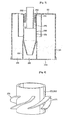
- the spiral circulation forming member 270 includes at least one blade 271 provided in the secondary cyclone body.
- the at least one blade 271 is provided to an outside circumferential surface of each of the air discharge pipe 252, and 262 inserted in an upper portion of the secondary cyclones 250, and 260.
- the air discharge pipes 252, and 262 serve to discharge the air passed through the dust separating step at the secondary cyclones 250, and 260 to an upper side of the upper cover 112, and it is preferable that the air discharge pipes 252, and 262 are cylindrical.
- the air discharge pipes 252, and 262 have axes the same with the secondary cyclone bodies 251, and 261, and pass the upper cover 112 in an up/down direction, respectively.
- the upper cover 112 has openings (not shown) passed through the upper cover 112 in an up/down direction in correspondence to the air discharge pipes 252, and 262.
- the at least one blade 271 has an inside surface formed as one body with an outside circumferential surface of the air discharge pipe 252, or 262, and an outside surface formed as one body with an inside circumferential surface of the secondary cyclone body 251, or 261.
- a plurality of helical blades 271 are provided to the outside circumferential surface of the air discharge pipe 252, or 262 at regular intervals in a circumferential direction of the air discharge pipe.
- the air introduced to the secondary cyclone bodies 251, and 261 passes through a dust separating step while circulating in a spiral in the secondary cyclone bodies 251, and 261 by the blades 271, and discharged to an upper side of the upper cover 112 through the air discharge pipes 252, and 262.
- each of the primary cyclones 210, and 280 has a hollow air discharge member 280 therein.
- the air passed through the dust separating step at the primary cyclones flows toward the secondary cyclone bodies 251, and 261 through the air discharge member 280.
- the air discharge member 280 has pass through holes 281 in an outside circumferential surface for pass through of the air, and prevents foreign matters larger than the pass through holes from introducing to the secondary cyclone bodies 251, and 261.
- the air discharge member 280 is provided between a top of the secondary cyclone body 251, or 261 and a bottom of the upper cover 112, and supported by the secondary cyclone body 251, or 261.
- the air discharge member 280 may have a cylindrical shape having an inside diameter the same with the inside diameter of the secondary cyclone body 251, or 261, or a cone shape having an inside diameter of a bottom thereof the same with the secondary cyclone body 251, or 261.
- the two secondary cyclones 250, and 260 are symmetry with respect to the plane of symmetry of the dust container 110.
- the dust container 110 there are secondary dust containers 131 for forming secondary dust collecting spaces in correspondence to the secondary cyclones, respectively.
- the secondary dust containers 131 are provided between the lower portions of the secondary cyclones 251, and 261, and the bottom of the dust container, and form an outside wall of the secondary dust collecting chamber 130.
- the secondary dust container 131 has a cylindrical shape substantially, with a bottom in close contact with the dust container 110, and a top formed as one body with an outside circumferential surface of the lower body of the secondary cyclone bodies 251, and 261.
- the secondary dust container 131 may have the bottom formed as one body with the bottom of the dust container 110, and the top in close contact with an outside circumferential surface of the lower body of the secondary cyclone body 251, or 261.
- a number of the secondary dust container 131 is the same with a number of the secondary cyclones, the number is not limited to this, but the number of the secondary dust container 131 may be one such that dust separated by the secondary cyclones is stored in the one secondary dust collecting chamber.
- the outside wall of the dust container 110 is formed of a material which can be see-through.
- an outside wall of the secondary dust container 110 is formed of a material which can be see-through.
- the air primarily cleaned as the comparatively large particles are separated therefrom is discharged to the secondary cyclones 250, and 260 through the air discharge members 212, and 222.
- the plurality of blades 271 form a spiral circulation of air inside of the secondary cyclone bodies 251, and 261, such that the air passed through a dust separation step in the secondary cyclone bodies 251, and 261 is discharged to an upper side of the upper cover 112 through the air discharge pipes 252, and 262, and therefrom to an outside of the cleaner body after passing through the predetermined air discharge flow passage in the cleaner body and the motor-fan assembly.
- a dust collecting device in accordance with another preferred embodiment of the present invention will be described with reference to FIGS 9 and 10 .
- the dust collecting device in accordance with another preferred embodiment of the present invention includes the dust container 110 which surrounds the cyclone unit in the dust collecting device in the foregoing embodiment of the present invention, and a filter 300 in the dust container 110.
- the filter 300 filters dust from the air from the dust container 110, and is provided on one side of the primary cyclones 210, and 220.
- an air discharge portion 112a for discharging air passed through the filter.
- a filter mounting portion 310 for mounting the filter.
- the air introduced to the primary cyclones 210, and 220 is discharged to an outside of the dust container 110 through two paths. That is, the dust collecting device of the embodiment has two air flow passages.
- a portion of the air introduced to the primary cyclones 210, and 220 is discharged to an outside of the dust container 110 through the secondary cyclones 250, and 260 and the air discharge pipes 252, and 262, and rest of the air is discharged to the outside of the dust container 110 through the filter 300.
- the filter 300 is provided to a rear of the primary cyclones 210, and 220, so that a portion of the air introduced to the primary cyclones 210, and 220 is discharged to the outside of the dust container 110 directly after passing through the filter via the primary dust collecting chamber 120.
- the dust collecting device of the present invention is applicable both to the canister type vacuum cleaner, and the upright type vacuum cleaner.
- the dust collecting device of the present invention having the foregoing design has the following advantages.
- the parallel arrangement of the two primary cyclones improves a dust collecting performance of the primary cyclone unit which separates a major portion of the dust, to improve a performance of the dust collecting device, on the whole.
- the symmetric exterior of the dust container in a left/right direction, to provide the suction pipe for guiding air to the primary cyclone unit at an upper center of the dust container improves air tightness to the cleaner body, and enables to reduce an air flow resistance.
- the sectional area of the dust storage portion formed larger than the cross sectional area of the primary cyclone unit permits to minimize an influence of the circulating air from the primary cyclone unit to a circulating air containing the dust, thereby improving a dust separating performance.
- the formation of the outside wall of the dust container of a material which can be see-through to enable easy determination of a dust amount in the primary dust collecting chamber which stores a major portion of the dust permits an appropriate selection of a time for emptying the dust container.
- the provision of the secondary cyclone in the primary cyclone permits to minimize an air flow distance, and an air flow loss, and to make an entire structure of the dust collecting device compact.
- the two air discharge paths from the dust container in the another preferred embodiment of the invention permits to reduce a load on the secondary cyclones, and an air resistance.
Landscapes
- Engineering & Computer Science (AREA)
- Mechanical Engineering (AREA)
- Filters For Electric Vacuum Cleaners (AREA)
- Cyclones (AREA)
Claims (18)
- Dispositif de collecte de poussière pour un aspirateur, comprenant :deux cyclones primaires parallèles (210, 220) pour séparer la poussière par un principe basé sur un cyclone ;caractérisé pardeux cyclones secondaires (250, 260) pour séparer la poussière introduite dans ceux-ci depuis les cyclones primaires (210, 220) par le principe basé sur un cyclone, les deux cyclones secondaires (250, 260) étant entouré par les cyclones primaires (210, 220) respectivement ; etun conteneur à poussière (110) pour stocker la poussière séparée par les cyclones primaires (210, 220) et par les cyclones secondaires (250, 260) ;une portion de guidage d'air aspiré (230) connectée au cyclone primaire pour guider l'air contenant de la poussière vers les cyclones primaires ;dans lequel la portion de guidage d'air aspiré (230) inclut :un tube de succion (231) ayant une portion d'entrée (231a) à une portion supérieure d'une surface circonférentielle extérieure du conteneur à poussière (110), etune paroi de guidage (232) pour guider l'air guidé par le tube de succion (231) vers les intérieurs des cyclones primaires (210, 220),dans lequel la paroi de guidage (232) est respectivement connectée au cyclone primaire (210, 220) et comprend une portion médiane (232a) en projection vers le tube de succion (231) pour scinder l'air fourni via le tube de succion (231) en deux côtés vers les cyclones primaires (210, 220).
- Dispositif de collecte de poussière selon la revendication 1, dans lequel le conteneur à poussière (106) présente un extérieur symétrique dans une direction gauche/droite.
- Dispositif de collecte de poussière selon la revendication 1, dans lequel la portion de guidage d'air aspiré (230) est symétrique par rapport à un plan de symétrie du conteneur à poussière (110).
- Dispositif de collecte de poussière selon la revendication 1, dans lequel les cyclones primaires (210, 220) sont dans le conteneur à poussière (110), et sont symétriques l'un de l'autre par rapport au plan de symétrie du conteneur à poussière (110).
- Dispositif de collecte de poussière selon la revendication 4, dans lequel les cyclones primaires (210, 220) sont prévus dans le conteneur à poussière (110) dans une direction montante/descendante.
- Dispositif de collecte de poussière selon la revendication 1, dans lequel les cyclones primaires (210, 220) ont des premières entrées entre la paroi de guidage (232) et le tube de succion (231), respectivement.
- Dispositif de collecte de poussière selon la revendication 6, dans lequel la paroi de guidage (232) est à l'opposé du tube de succion (231) et comporte une extrémité, et son autre extrémité est connectée à une bordure latérale de l'une des premières entrées (211, 221), et à une bordure latérale de l'autre des premières entrées (211, 221) respectivement.
- Dispositif de collecte de poussière selon la revendication 5, dans lequel les cyclones primaires (210, 220) ont des extrémités supérieures connectées à un couvercle supérieur (112) à ouvrir, prévu sur une portion supérieure du conteneur à poussière (110).
- Dispositif de collecte de poussière selon la revendication 5, dans lequel les cyclones primaires (210, 220) sont espacés à des hauteurs prédéterminées depuis un fond du conteneur à poussière (110).
- Dispositif de collecte de poussière selon la revendication 1, comprenant en outre un filtre (300) dans le conteneur à poussière (110) pour filtrer la poussière hors de l'air provenant du conteneur à poussière (110).
- Dispositif de collecte de poussière selon la revendication 10, dans lequel le filtre (300) est sur un côté des cyclones primaires (210, 220), de sorte qu'une portion de l'air introduit vers les cyclones primaires (210, 220) est déchargée vers l'extérieur du conteneur à poussière (110) via les cyclones secondaires (250, 260), et le reste de l'air est déchargé vers l'extérieur du conteneur à poussière (110) via le filtre (300).
- Dispositif de collecte de poussière selon la revendication 1, dans lequel le conteneur à poussière (110) forme un fond de la chambre de collecte de poussière primaire (120) pour stocker la poussière séparée par les cyclones primaires (210, 220), et un fond de la chambre de collecte de poussière secondaire (130) pour stocker la poussière séparée par les cyclones secondaires (250, 260), et inclut un fond susceptible d'être ouvert.
- Dispositif de collecte de poussière selon la revendication 1, dans lequel les cyclones secondaires (250, 260) incluent :des corps de cyclones secondaires (251, 261) montés dans les cyclones secondaires (250, 260) dans une direction montante/descendante, respectivement ; etun élément de formation de circulation en spirale (270) dans chacun des corps de cyclones secondaires (251, 261).
- Dispositif de collecte de poussière selon la revendication 13, dans lequel l'élément de formation de circulation en spirale (270) inclut au moins une pale (271) prévue dans une portion supérieure du corps de cyclone secondaire (251, 261).
- Dispositif de collecte de poussière selon la revendication 14, dans lequel ladite au moins une pale (271) est prévue sur une surface circonférentielle extérieure d'un tube de décharge d'air (252, 262) insérée dans la portion supérieure du corps de cyclone secondaire (251, 261) pour guider l'air déchargé depuis le corps de cyclone secondaire (251, 261).
- Dispositif de collecte de poussière selon la revendication 13, dans lequel les cyclones secondaires (250, 260) incluent des éléments de décharge d'air creux (250) dans les cyclones primaires (210, 220) respectivement, ayant chacun une pluralité de trous traversants (281) dans une surface circonférentielle extérieure pour le passage de l'air qui s'écoule vers le corps de cyclone secondaire (251, 261).
- Dispositif de collecte de poussière selon la revendication 16, dans lequel l'élément de décharge d'air (280) est prévu entre le sommet du corps de cyclone secondaire (251, 261) et le sommet du conteneur à poussière (110).
- Dispositif de collecte de poussière selon la revendication 13, dans lequel le conteneur à poussière (110) inclut des conteneurs à poussière secondaires (131) entre des portions inférieures des corps de cyclones secondaires (251, 261) et le fond du conteneur à poussière (110), entourés par une surface circonférentielle intérieure du conteneur à poussière (110), pour stocker la poussière séparée par le corps de cyclone secondaire (251, 261).
Applications Claiming Priority (1)
| Application Number | Priority Date | Filing Date | Title |
|---|---|---|---|
| PCT/KR2005/002684 WO2007021042A1 (fr) | 2005-08-17 | 2005-08-17 | Dispositif de collecte de poussière pour aspirateur |
Publications (3)
| Publication Number | Publication Date |
|---|---|
| EP1915083A1 EP1915083A1 (fr) | 2008-04-30 |
| EP1915083A4 EP1915083A4 (fr) | 2009-11-18 |
| EP1915083B1 true EP1915083B1 (fr) | 2015-03-18 |
Family
ID=37757685
Family Applications (1)
| Application Number | Title | Priority Date | Filing Date |
|---|---|---|---|
| EP05780568.1A Expired - Lifetime EP1915083B1 (fr) | 2005-08-17 | 2005-08-17 | Dispositif de collecte de poussière pour aspirateur |
Country Status (5)
| Country | Link |
|---|---|
| US (1) | US7935159B2 (fr) |
| EP (1) | EP1915083B1 (fr) |
| KR (1) | KR100934668B1 (fr) |
| CN (1) | CN101282674B (fr) |
| WO (1) | WO2007021042A1 (fr) |
Families Citing this family (15)
| Publication number | Priority date | Publication date | Assignee | Title |
|---|---|---|---|---|
| CN101262806B (zh) | 2005-08-17 | 2010-10-13 | Lg电子株式会社 | 用于真空吸尘器的集尘装置 |
| US7695537B2 (en) * | 2007-07-23 | 2010-04-13 | Chieh-Yuan Cheng | Dust collector with a function of secondary collection |
| KR101455676B1 (ko) * | 2008-01-02 | 2014-10-30 | 삼성전자주식회사 | 듀얼 싸이클론 집진장치 및 이를 구비하는 청소기 |
| JP5306968B2 (ja) * | 2009-11-06 | 2013-10-02 | 三菱電機株式会社 | 電気掃除機 |
| GB2499620B (en) * | 2012-02-21 | 2019-05-22 | Caltec Production Solutions Ltd | Fluid separator |
| CN103536249B (zh) * | 2012-07-12 | 2017-04-12 | 湖北随州合力汽车销售有限公司 | 一种吸尘车的除尘分离箱 |
| JP5472417B1 (ja) * | 2012-09-28 | 2014-04-16 | 三菱電機株式会社 | 遠心分離装置 |
| WO2014072469A1 (fr) | 2012-11-09 | 2014-05-15 | Aktiebolaget Electrolux | Agencement de séparateur de poussière cyclone, séparateur de poussière cyclone et aspirateur cyclone |
| KR102202268B1 (ko) * | 2014-12-17 | 2021-01-13 | 엘지전자 주식회사 | 진공 청소기용 집진장치 |
| CN104545695B (zh) * | 2015-01-28 | 2016-08-31 | 莱克电气股份有限公司 | 一种二级尘气分离结构及包含该结构的尘杯 |
| US10814259B2 (en) * | 2015-04-30 | 2020-10-27 | Atlas Copco Airpower, Naamloze Vennootschap | Device for separating liquid from a gas stream coming from a liquid injected vacuum pump or compressor |
| US20180036653A1 (en) * | 2016-08-03 | 2018-02-08 | Jci Cyclonic Technologies Ltd. | Dual cyclone separator |
| BE1025205B1 (nl) * | 2017-04-27 | 2018-12-11 | Atlas Copco Airpower Naamloze Vennootschap | Inrichting voor het afscheiden van vloeistof uit een gasstroom in een vloeistof-geïnjecteerde compressor en werkwijze daarvoor |
| CN111227711A (zh) * | 2020-03-24 | 2020-06-05 | 苏州市伟克斯电器有限公司 | 集尘桶组件以及吸尘器 |
| USD1032980S1 (en) * | 2022-08-29 | 2024-06-25 | Nantong Suning Environmental Protection Technology Co., Ltd | Dust collector |
Family Cites Families (13)
| Publication number | Priority date | Publication date | Assignee | Title |
|---|---|---|---|---|
| GB2362341B (en) | 2000-05-16 | 2002-12-04 | Samsung Kwangju Electronics Co | Upright-type vacuum cleaner |
| GB0104668D0 (en) | 2001-02-24 | 2001-04-11 | Dyson Ltd | Cyclonic separating apparatus |
| JP3659191B2 (ja) * | 2001-05-08 | 2005-06-15 | 松下電器産業株式会社 | 遠心力集塵装置及びそれを用いた電気掃除機 |
| JP4131927B2 (ja) | 2002-10-15 | 2008-08-13 | 株式会社東芝 | 電気掃除機 |
| CN2592103Y (zh) | 2002-12-04 | 2003-12-17 | 深圳索雷克家用电器有限公司 | 立式吸尘器 |
| GB2399780A (en) | 2003-03-28 | 2004-09-29 | Dyson Ltd | Arrangement of cyclones for noise damping |
| EP1488729A3 (fr) | 2003-06-16 | 2008-03-19 | Matsushita Electric Industrial Co., Ltd. | Receptacle de poubelle pour aspirateur |
| CN2631412Y (zh) | 2003-07-25 | 2004-08-11 | 深圳索雷克家用电器有限公司 | 二次旋风吸尘器 |
| GB2406067B (en) * | 2003-09-08 | 2006-11-08 | Samsung Kwangju Electronics Co | Cyclonic dust-separating apparatus |
| KR100592098B1 (ko) | 2004-02-11 | 2006-06-22 | 삼성광주전자 주식회사 | 진공청소기의 사이클론 집진장치 |
| US7309368B2 (en) | 2004-02-11 | 2007-12-18 | Samsung Gwangju Electronics Co., Ltd. | Cyclone dust-collecting apparatus |
| KR100645376B1 (ko) * | 2005-03-29 | 2006-11-14 | 삼성광주전자 주식회사 | 멀티사이클론 집진장치 |
| KR101472776B1 (ko) * | 2007-11-05 | 2014-12-17 | 삼성전자주식회사 | 진공청소기의 멀티 사이클론 집진장치 |
-
2005
- 2005-08-17 US US11/990,503 patent/US7935159B2/en not_active Expired - Fee Related
- 2005-08-17 WO PCT/KR2005/002684 patent/WO2007021042A1/fr not_active Ceased
- 2005-08-17 EP EP05780568.1A patent/EP1915083B1/fr not_active Expired - Lifetime
- 2005-08-17 KR KR1020087003510A patent/KR100934668B1/ko not_active Expired - Fee Related
- 2005-08-17 CN CN2005800513232A patent/CN101282674B/zh not_active Expired - Fee Related
Also Published As
| Publication number | Publication date |
|---|---|
| CN101282674B (zh) | 2010-12-15 |
| KR20080032181A (ko) | 2008-04-14 |
| KR100934668B1 (ko) | 2009-12-31 |
| US20090199359A1 (en) | 2009-08-13 |
| US7935159B2 (en) | 2011-05-03 |
| CN101282674A (zh) | 2008-10-08 |
| EP1915083A1 (fr) | 2008-04-30 |
| EP1915083A4 (fr) | 2009-11-18 |
| WO2007021042A1 (fr) | 2007-02-22 |
Similar Documents
| Publication | Publication Date | Title |
|---|---|---|
| EP1915084B2 (fr) | Dispositif de collecte de poussière pour aspirateur | |
| US7857878B2 (en) | Dust collection unit for vacuum cleaner | |
| EP1915083B1 (fr) | Dispositif de collecte de poussière pour aspirateur | |
| US7935162B2 (en) | Dust collecting device for vacuum cleaner | |
| EP1915082B1 (fr) | Dispositif de collecte de poussiere pour aspirateur | |
| EP2142065B1 (fr) | Dispositif de séparation de poussière d'aspirateur | |
| EP1676514B1 (fr) | Aspirateur | |
| KR100546627B1 (ko) | 진공 청소기의 집진장치 | |
| KR101306695B1 (ko) | 집진장치 | |
| EP1679026A2 (fr) | Appareil permettant de recueillir des particules de poussiere et aspirateur comprenant celui-ci | |
| KR100546628B1 (ko) | 진공 청소기의 집진장치 | |
| KR100556444B1 (ko) | 진공 청소기의 집진장치 | |
| KR101250038B1 (ko) | 진공 청소기 | |
| KR100556443B1 (ko) | 진공 청소기의 집진장치 | |
| KR100546624B1 (ko) | 청소기의 집진장치 |
Legal Events
| Date | Code | Title | Description |
|---|---|---|---|
| PUAI | Public reference made under article 153(3) epc to a published international application that has entered the european phase |
Free format text: ORIGINAL CODE: 0009012 |
|
| 17P | Request for examination filed |
Effective date: 20080206 |
|
| AK | Designated contracting states |
Kind code of ref document: A1 Designated state(s): AT BE BG CH CY CZ DE DK EE ES FI FR GB GR HU IE IS IT LI LT LU LV MC NL PL PT RO SE SI SK TR |
|
| RIN1 | Information on inventor provided before grant (corrected) |
Inventor name: LEE, SUNG HWA Inventor name: JEONG, KYEONG SEON,C/O DAC RESEARCH INSTITUTE, LG Inventor name: SON, YOUNG BOK Inventor name: HYUN, KIE TAK,C/O DAC RESEARCH INSTITUTE, LG ELECT Inventor name: KIM, IL JOONG |
|
| A4 | Supplementary search report drawn up and despatched |
Effective date: 20091020 |
|
| 17Q | First examination report despatched |
Effective date: 20100119 |
|
| DAX | Request for extension of the european patent (deleted) | ||
| GRAP | Despatch of communication of intention to grant a patent |
Free format text: ORIGINAL CODE: EPIDOSNIGR1 |
|
| INTG | Intention to grant announced |
Effective date: 20141009 |
|
| RAP1 | Party data changed (applicant data changed or rights of an application transferred) |
Owner name: LG ELECTRONICS INC. |
|
| GRAS | Grant fee paid |
Free format text: ORIGINAL CODE: EPIDOSNIGR3 |
|
| GRAA | (expected) grant |
Free format text: ORIGINAL CODE: 0009210 |
|
| AK | Designated contracting states |
Kind code of ref document: B1 Designated state(s): AT BE BG CH CY CZ DE DK EE ES FI FR GB GR HU IE IS IT LI LT LU LV MC NL PL PT RO SE SI SK TR |
|
| REG | Reference to a national code |
Ref country code: GB Ref legal event code: FG4D |
|
| REG | Reference to a national code |
Ref country code: CH Ref legal event code: EP |
|
| REG | Reference to a national code |
Ref country code: IE Ref legal event code: FG4D |
|
| REG | Reference to a national code |
Ref country code: AT Ref legal event code: REF Ref document number: 715987 Country of ref document: AT Kind code of ref document: T Effective date: 20150415 |
|
| REG | Reference to a national code |
Ref country code: DE Ref legal event code: R096 Ref document number: 602005046095 Country of ref document: DE Effective date: 20150430 |
|
| REG | Reference to a national code |
Ref country code: NL Ref legal event code: VDEP Effective date: 20150318 |
|
| REG | Reference to a national code |
Ref country code: NL Ref legal event code: VDEP Effective date: 20150318 |
|
| PG25 | Lapsed in a contracting state [announced via postgrant information from national office to epo] |
Ref country code: SE Free format text: LAPSE BECAUSE OF FAILURE TO SUBMIT A TRANSLATION OF THE DESCRIPTION OR TO PAY THE FEE WITHIN THE PRESCRIBED TIME-LIMIT Effective date: 20150318 Ref country code: LT Free format text: LAPSE BECAUSE OF FAILURE TO SUBMIT A TRANSLATION OF THE DESCRIPTION OR TO PAY THE FEE WITHIN THE PRESCRIBED TIME-LIMIT Effective date: 20150318 Ref country code: FI Free format text: LAPSE BECAUSE OF FAILURE TO SUBMIT A TRANSLATION OF THE DESCRIPTION OR TO PAY THE FEE WITHIN THE PRESCRIBED TIME-LIMIT Effective date: 20150318 |
|
| REG | Reference to a national code |
Ref country code: AT Ref legal event code: MK05 Ref document number: 715987 Country of ref document: AT Kind code of ref document: T Effective date: 20150318 |
|
| REG | Reference to a national code |
Ref country code: LT Ref legal event code: MG4D |
|
| PG25 | Lapsed in a contracting state [announced via postgrant information from national office to epo] |
Ref country code: GR Free format text: LAPSE BECAUSE OF FAILURE TO SUBMIT A TRANSLATION OF THE DESCRIPTION OR TO PAY THE FEE WITHIN THE PRESCRIBED TIME-LIMIT Effective date: 20150619 Ref country code: LV Free format text: LAPSE BECAUSE OF FAILURE TO SUBMIT A TRANSLATION OF THE DESCRIPTION OR TO PAY THE FEE WITHIN THE PRESCRIBED TIME-LIMIT Effective date: 20150318 |
|
| PG25 | Lapsed in a contracting state [announced via postgrant information from national office to epo] |
Ref country code: NL Free format text: LAPSE BECAUSE OF FAILURE TO SUBMIT A TRANSLATION OF THE DESCRIPTION OR TO PAY THE FEE WITHIN THE PRESCRIBED TIME-LIMIT Effective date: 20150318 |
|
| PG25 | Lapsed in a contracting state [announced via postgrant information from national office to epo] |
Ref country code: SK Free format text: LAPSE BECAUSE OF FAILURE TO SUBMIT A TRANSLATION OF THE DESCRIPTION OR TO PAY THE FEE WITHIN THE PRESCRIBED TIME-LIMIT Effective date: 20150318 Ref country code: EE Free format text: LAPSE BECAUSE OF FAILURE TO SUBMIT A TRANSLATION OF THE DESCRIPTION OR TO PAY THE FEE WITHIN THE PRESCRIBED TIME-LIMIT Effective date: 20150318 Ref country code: RO Free format text: LAPSE BECAUSE OF FAILURE TO SUBMIT A TRANSLATION OF THE DESCRIPTION OR TO PAY THE FEE WITHIN THE PRESCRIBED TIME-LIMIT Effective date: 20150318 Ref country code: ES Free format text: LAPSE BECAUSE OF FAILURE TO SUBMIT A TRANSLATION OF THE DESCRIPTION OR TO PAY THE FEE WITHIN THE PRESCRIBED TIME-LIMIT Effective date: 20150318 Ref country code: PT Free format text: LAPSE BECAUSE OF FAILURE TO SUBMIT A TRANSLATION OF THE DESCRIPTION OR TO PAY THE FEE WITHIN THE PRESCRIBED TIME-LIMIT Effective date: 20150720 Ref country code: CZ Free format text: LAPSE BECAUSE OF FAILURE TO SUBMIT A TRANSLATION OF THE DESCRIPTION OR TO PAY THE FEE WITHIN THE PRESCRIBED TIME-LIMIT Effective date: 20150318 |
|
| PG25 | Lapsed in a contracting state [announced via postgrant information from national office to epo] |
Ref country code: PL Free format text: LAPSE BECAUSE OF FAILURE TO SUBMIT A TRANSLATION OF THE DESCRIPTION OR TO PAY THE FEE WITHIN THE PRESCRIBED TIME-LIMIT Effective date: 20150318 Ref country code: AT Free format text: LAPSE BECAUSE OF FAILURE TO SUBMIT A TRANSLATION OF THE DESCRIPTION OR TO PAY THE FEE WITHIN THE PRESCRIBED TIME-LIMIT Effective date: 20150318 Ref country code: IS Free format text: LAPSE BECAUSE OF FAILURE TO SUBMIT A TRANSLATION OF THE DESCRIPTION OR TO PAY THE FEE WITHIN THE PRESCRIBED TIME-LIMIT Effective date: 20150718 |
|
| REG | Reference to a national code |
Ref country code: DE Ref legal event code: R097 Ref document number: 602005046095 Country of ref document: DE |
|
| PG25 | Lapsed in a contracting state [announced via postgrant information from national office to epo] |
Ref country code: IT Free format text: LAPSE BECAUSE OF FAILURE TO SUBMIT A TRANSLATION OF THE DESCRIPTION OR TO PAY THE FEE WITHIN THE PRESCRIBED TIME-LIMIT Effective date: 20150318 |
|
| PLBE | No opposition filed within time limit |
Free format text: ORIGINAL CODE: 0009261 |
|
| STAA | Information on the status of an ep patent application or granted ep patent |
Free format text: STATUS: NO OPPOSITION FILED WITHIN TIME LIMIT |
|
| PG25 | Lapsed in a contracting state [announced via postgrant information from national office to epo] |
Ref country code: DK Free format text: LAPSE BECAUSE OF FAILURE TO SUBMIT A TRANSLATION OF THE DESCRIPTION OR TO PAY THE FEE WITHIN THE PRESCRIBED TIME-LIMIT Effective date: 20150318 |
|
| 26N | No opposition filed |
Effective date: 20151221 |
|
| PG25 | Lapsed in a contracting state [announced via postgrant information from national office to epo] |
Ref country code: SI Free format text: LAPSE BECAUSE OF FAILURE TO SUBMIT A TRANSLATION OF THE DESCRIPTION OR TO PAY THE FEE WITHIN THE PRESCRIBED TIME-LIMIT Effective date: 20150318 |
|
| PG25 | Lapsed in a contracting state [announced via postgrant information from national office to epo] |
Ref country code: MC Free format text: LAPSE BECAUSE OF FAILURE TO SUBMIT A TRANSLATION OF THE DESCRIPTION OR TO PAY THE FEE WITHIN THE PRESCRIBED TIME-LIMIT Effective date: 20150318 Ref country code: LU Free format text: LAPSE BECAUSE OF FAILURE TO SUBMIT A TRANSLATION OF THE DESCRIPTION OR TO PAY THE FEE WITHIN THE PRESCRIBED TIME-LIMIT Effective date: 20150817 |
|
| REG | Reference to a national code |
Ref country code: CH Ref legal event code: PL |
|
| GBPC | Gb: european patent ceased through non-payment of renewal fee |
Effective date: 20150817 |
|
| PG25 | Lapsed in a contracting state [announced via postgrant information from national office to epo] |
Ref country code: LI Free format text: LAPSE BECAUSE OF NON-PAYMENT OF DUE FEES Effective date: 20150831 Ref country code: CH Free format text: LAPSE BECAUSE OF NON-PAYMENT OF DUE FEES Effective date: 20150831 |
|
| REG | Reference to a national code |
Ref country code: IE Ref legal event code: MM4A |
|
| REG | Reference to a national code |
Ref country code: FR Ref legal event code: ST Effective date: 20160429 |
|
| PG25 | Lapsed in a contracting state [announced via postgrant information from national office to epo] |
Ref country code: GB Free format text: LAPSE BECAUSE OF NON-PAYMENT OF DUE FEES Effective date: 20150817 Ref country code: IE Free format text: LAPSE BECAUSE OF NON-PAYMENT OF DUE FEES Effective date: 20150817 |
|
| PG25 | Lapsed in a contracting state [announced via postgrant information from national office to epo] |
Ref country code: BE Free format text: LAPSE BECAUSE OF FAILURE TO SUBMIT A TRANSLATION OF THE DESCRIPTION OR TO PAY THE FEE WITHIN THE PRESCRIBED TIME-LIMIT Effective date: 20150318 Ref country code: FR Free format text: LAPSE BECAUSE OF NON-PAYMENT OF DUE FEES Effective date: 20150831 |
|
| PG25 | Lapsed in a contracting state [announced via postgrant information from national office to epo] |
Ref country code: HU Free format text: LAPSE BECAUSE OF FAILURE TO SUBMIT A TRANSLATION OF THE DESCRIPTION OR TO PAY THE FEE WITHIN THE PRESCRIBED TIME-LIMIT; INVALID AB INITIO Effective date: 20050817 Ref country code: BG Free format text: LAPSE BECAUSE OF FAILURE TO SUBMIT A TRANSLATION OF THE DESCRIPTION OR TO PAY THE FEE WITHIN THE PRESCRIBED TIME-LIMIT Effective date: 20150318 |
|
| PG25 | Lapsed in a contracting state [announced via postgrant information from national office to epo] |
Ref country code: CY Free format text: LAPSE BECAUSE OF FAILURE TO SUBMIT A TRANSLATION OF THE DESCRIPTION OR TO PAY THE FEE WITHIN THE PRESCRIBED TIME-LIMIT Effective date: 20150318 |
|
| PG25 | Lapsed in a contracting state [announced via postgrant information from national office to epo] |
Ref country code: TR Free format text: LAPSE BECAUSE OF FAILURE TO SUBMIT A TRANSLATION OF THE DESCRIPTION OR TO PAY THE FEE WITHIN THE PRESCRIBED TIME-LIMIT Effective date: 20150318 |
|
| PGFP | Annual fee paid to national office [announced via postgrant information from national office to epo] |
Ref country code: DE Payment date: 20190705 Year of fee payment: 15 |
|
| REG | Reference to a national code |
Ref country code: DE Ref legal event code: R119 Ref document number: 602005046095 Country of ref document: DE |
|
| PG25 | Lapsed in a contracting state [announced via postgrant information from national office to epo] |
Ref country code: DE Free format text: LAPSE BECAUSE OF NON-PAYMENT OF DUE FEES Effective date: 20210302 |