EP1915519B1 - Exhaust pipe - Google Patents
Exhaust pipe Download PDFInfo
- Publication number
- EP1915519B1 EP1915519B1 EP06808051A EP06808051A EP1915519B1 EP 1915519 B1 EP1915519 B1 EP 1915519B1 EP 06808051 A EP06808051 A EP 06808051A EP 06808051 A EP06808051 A EP 06808051A EP 1915519 B1 EP1915519 B1 EP 1915519B1
- Authority
- EP
- European Patent Office
- Prior art keywords
- tube
- fibres
- conduit according
- holding layer
- inner tube
- Prior art date
- Legal status (The legal status is an assumption and is not a legal conclusion. Google has not performed a legal analysis and makes no representation as to the accuracy of the status listed.)
- Not-in-force
Links
Images
Classifications
-
- F—MECHANICAL ENGINEERING; LIGHTING; HEATING; WEAPONS; BLASTING
- F01—MACHINES OR ENGINES IN GENERAL; ENGINE PLANTS IN GENERAL; STEAM ENGINES
- F01N—GAS-FLOW SILENCERS OR EXHAUST APPARATUS FOR MACHINES OR ENGINES IN GENERAL; GAS-FLOW SILENCERS OR EXHAUST APPARATUS FOR INTERNAL-COMBUSTION ENGINES
- F01N13/00—Exhaust or silencing apparatus characterised by constructional features
- F01N13/08—Other arrangements or adaptations of exhaust conduits
- F01N13/10—Other arrangements or adaptations of exhaust conduits of exhaust manifolds
-
- F—MECHANICAL ENGINEERING; LIGHTING; HEATING; WEAPONS; BLASTING
- F01—MACHINES OR ENGINES IN GENERAL; ENGINE PLANTS IN GENERAL; STEAM ENGINES
- F01N—GAS-FLOW SILENCERS OR EXHAUST APPARATUS FOR MACHINES OR ENGINES IN GENERAL; GAS-FLOW SILENCERS OR EXHAUST APPARATUS FOR INTERNAL-COMBUSTION ENGINES
- F01N13/00—Exhaust or silencing apparatus characterised by constructional features
- F01N13/14—Exhaust or silencing apparatus characterised by constructional features having thermal insulation
-
- F—MECHANICAL ENGINEERING; LIGHTING; HEATING; WEAPONS; BLASTING
- F01—MACHINES OR ENGINES IN GENERAL; ENGINE PLANTS IN GENERAL; STEAM ENGINES
- F01N—GAS-FLOW SILENCERS OR EXHAUST APPARATUS FOR MACHINES OR ENGINES IN GENERAL; GAS-FLOW SILENCERS OR EXHAUST APPARATUS FOR INTERNAL-COMBUSTION ENGINES
- F01N13/00—Exhaust or silencing apparatus characterised by constructional features
- F01N13/08—Other arrangements or adaptations of exhaust conduits
- F01N13/10—Other arrangements or adaptations of exhaust conduits of exhaust manifolds
- F01N13/102—Other arrangements or adaptations of exhaust conduits of exhaust manifolds having thermal insulation
-
- F—MECHANICAL ENGINEERING; LIGHTING; HEATING; WEAPONS; BLASTING
- F01—MACHINES OR ENGINES IN GENERAL; ENGINE PLANTS IN GENERAL; STEAM ENGINES
- F01N—GAS-FLOW SILENCERS OR EXHAUST APPARATUS FOR MACHINES OR ENGINES IN GENERAL; GAS-FLOW SILENCERS OR EXHAUST APPARATUS FOR INTERNAL-COMBUSTION ENGINES
- F01N13/00—Exhaust or silencing apparatus characterised by constructional features
- F01N13/16—Selection of particular materials
-
- F—MECHANICAL ENGINEERING; LIGHTING; HEATING; WEAPONS; BLASTING
- F01—MACHINES OR ENGINES IN GENERAL; ENGINE PLANTS IN GENERAL; STEAM ENGINES
- F01N—GAS-FLOW SILENCERS OR EXHAUST APPARATUS FOR MACHINES OR ENGINES IN GENERAL; GAS-FLOW SILENCERS OR EXHAUST APPARATUS FOR INTERNAL-COMBUSTION ENGINES
- F01N2310/00—Selection of sound absorbing or insulating material
- F01N2310/02—Mineral wool, e.g. glass wool, rock wool, asbestos or the like
Definitions
- the elements of the exhaust line between the engine outlet and the pollution control members comprise an inner ceramic tube surrounded by an outer tube of metal between which is interposed an insulating material.
- the ceramic tube because of its low thermal inertia, greatly reduces the heat transfer of the exhaust gas to the ceramic tube.
- the low thermal expansion of the inner ceramic tube makes it possible to produce monobloc internal pipes even for engines that release exhaust gases at very high temperatures, in particular greater than 1000.degree. C. without risk of thermomechanical rupture.
- Such a structure is used in particular in the exhaust manifolds provided immediately at the output of the engine.
- Such a collector is described for example in the document US 6,725,656 B2 .
- the thick layer of ceramic fibers has a thickness of between 1 mm and 40 mm and preferably between 2 mm and 20 mm.
- a so-called thin layer of stress isolation is provided between the thick layer of ceramic fibers and the outer tube of metal.
- This thin layer of stress isolation is between 0.05 mm and 2 mm and preferably between 0.1 mm and 0.5 mm.
- This layer of stress insulation is designed to absorb the vibrations of the engine and the road to prevent the destruction of the thick ceramic fiber layer.
- This layer also attenuates the vibrations, in particular by compensating the differential thermal expansions between the layer of thick ceramic fibers and the outer tube of metal during the heating of the exhaust line. Indeed, when the inner tube is traversed by gases at high temperatures, there are significant differential thermal expansions because the dense inner ceramic tube and the thick layer of ceramic fibers have relatively low expansion coefficients in comparison with the outer tube made of metal.
- US 6,725,656 B2 thus describes a multilayer structure comprising at least a dense ceramic inner layer, a thermally insulating thick layer of ceramic fibers and a metal layer. This structure is optionally supplemented by a thin layer of stress insulation for protecting the thick layer of ceramic fibers from vibrations.
- an object of the invention is an exhaust duct for satisfactory heat delivery comprising an inorganic matrix composite inner pipe held in an outer metal structure.
- the subject of the invention is an exhaust duct of the aforementioned type, characterized in that the thickness of the holding layer is between 2 mm and 10 mm, and preferably between 3 mm and 6 mm, and in that the minimum holding pressure exerted by the holding layer on the inner tube is between 10 -4 MPa and 10 -1 MPa.
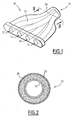
- the exhaust manifold 10 illustrated on the figure 1 is intended to be disposed at the output of a heat engine at the entrance of an exhaust line of a motor vehicle.
- This exhaust line comprises downstream of the manifold 10, possibly a supercharging system (turbo) and one or more depollution elements capable of operating at high temperature.
- Turbo supercharging system
- the collector 10 has a plurality of inlets 12 converging towards an outlet flange 14.
- the inlets 12 are connected to the outlet flange 14 by ducts 20 opening into each other.
- each conduit 20 comprises an inner tube 22 of inorganic matrix composite, in particular ceramic, and an outer metal tube 24 between which is disposed a holding layer 26 made of a ceramic fibrous material.
- the conduit consists of only three layers 22, 24 and 26.
- the outer tube 24 is formed of a metal wall having a thickness of between 0.5 and 3 mm. According to a first embodiment, the outer tube 24 is a cylindrical metal tube including steel, aluminum or titanium.
- the outer tube 24 is formed of two metal half-shells 27 in the form of gutters joined by opposite longitudinal joints 28.
- the outer tube 24 is provided with flanges allowing its connection with, upstream, the engine and downstream, the exhaust line of the vehicle.
- the choice of a metal outer tube is justified by the need to ensure optimum sealing upstream of the pollution control elements, and in particular at the junction of the outer tube with the upstream and downstream metal flanges.
- the authorized leakage flow rate is 25 liters / hour, at 20 ° C. under 1.3 bars.
- the inner tube 22 is a tube formed from an inorganic matrix composite material, in particular a ceramic material. Examples of inorganic matrix composite materials capable of forming the inner tube 22 are given in the patent applications US6134881 and W02004106705 . These materials are formed by the combination of a matrix consisting of at least one inorganic polymer, preferably of geopolymer type, based on aluminosilicate.
- the inner tube 22 is formed of a wall having a thickness of less than 2 mm.
- the holding layer 26 has a thickness of between 2 and 10 mm. It is preferably between 3 and 6 mm.
- the holding layer 26 is formed of a layer of ceramic fibers, especially long ceramic fibers preferably associated with an organic binder and / or inorganic.
- the organic binder is only useful when placing the holding layer around the inner tube; it is consumed during the first temperature rise of the exhaust duct on the vehicle. This binder represents from 0 to 15% by weight of the new holding layer.
- the inorganic binder is used when it is necessary to ensure better cohesion between the fibers during operation of the vehicle and must not be burned.
- This binder represents from 0 to 10% by weight of the organic binder-free holding layer.
- the ceramic fibers represent 90 to 100% by weight of the holding layer, the remainder being the inorganic binder.
- the ceramic fibers present in the holding layer 26 are selected from the group consisting of silica fibers, alumina fibers, zirconium fibers, borosilicate alumina fibers and a mixture thereof.
- the sheets may be needled, which improves their behavior over time.
- the fibers used are mullite fibers combining alumina and silica in a ratio of 72% and 28%, respectively.
- the density of the material constituting the holding layer is between 500 g / m 2 and 3000 g / m 2 .
- This holding layer 26 must maintain the inner tube 22 in the outer tube 24 regardless of the operating conditions.
- the minimum pressure to be applied to maintain said inner tube in the metal tube is determined.
- This minimum pressure takes into account, in addition to the above mentioned solicitations, a specific corrective factor of the operating behavior of the inner ceramic tube and the holding layer. A coefficient of friction intervenes in this corrective factor.
- the material constituting the holding layer is chosen so that the coefficient of friction of the damping layer against the surfaces of the inner and outer tubes is between 0.15 and 0.7.
- the minimum holding pressure is between 10 -4 and 10 -1 MPa and preferably between 10 -3 MPa and 5.10 -2 MPa.
- the value of 10 -3 MPa corresponds to an inner tube of 100 grams having a contact area of 40 dm 2 with the holding layer subjected to an acceleration of 10 g and a pressure drop of 100 Pa. This pressure drop is induced by the friction of the gases against the wall of the inner tube.
- the value of 5.10 -2 MPa corresponds to an internal tube of 200 grams having a contact surface of 20 dm 2 with the holding layer and subjected to an acceleration of 40 g and a pressure drop of 250 Pa.
- GBD Gap Bulk Density
- Density is a characteristic of the tablecloth.
- the usable GBD range is 0.1 to 0.6. The minimum value is given to avoid vibrational deterioration of the fibers, the maximum value is given to avoid the deterioration of fibers by compression.
- the pressure exerted will be greater than the minimum holding pressure and less than the maximum pressure supported. by the fibers and the inner tube. It is still necessary to take into account that, in use, the clearance between the inner tube and the outer tube may vary by plus or minus 1 mm due to the differential expansion between the inner tube and the outer tube.
- the GBD is 0.3.
- the holding pressure exerted by the ply on the internal ceramic matrix composite tube is then, for the chosen type of ply, 0.2 MPa.
- This GBD of 0.3 is well within the recommended range of GBD.This pressure is greater than the minimum holding pressure calculated for this application (5.10 -2 MPa) and lower than the mechanical strength of the inner tube.
- the maximum clearance for this same application is 4.25 mm, corresponding to a GBD of 0.22 and a holding pressure of 6.10 -2 MPa.
- the GBD remains within the range of use of the web and the induced pressure remains above the minimum holding pressure.
- the holding material correctly ensures the maintenance of the inner tube of inorganic matrix composite in the outer metal tube regardless of the temperature of the exhaust line and the flow conditions. gaseous and acceleration to which the inner tube is subjected without deteriorating or damaging the inner tube.
Landscapes
- Engineering & Computer Science (AREA)
- Chemical & Material Sciences (AREA)
- Combustion & Propulsion (AREA)
- Mechanical Engineering (AREA)
- General Engineering & Computer Science (AREA)
- Exhaust Silencers (AREA)
- Steroid Compounds (AREA)
- Valve Device For Special Equipments (AREA)
- Seal Device For Vehicle (AREA)
Abstract
Description
La présente invention concerne un conduit d'échappement comportant, disposés de manière concentrique :
- un tube interne en composite à matrice inorganique ;
- un tube externe métallique ; et
- une couche de maintien d'un matériau fibreux.
- an inner tube of inorganic matrix composite;
- a metal outer tube; and
- a layer for holding a fibrous material.
De nos jours, l'implantation d'organes de dépollution dans les lignes d'échappement nécessite une gestion précise des flux thermiques du moteur jusqu'à la sortie d'échappement. En particulier, il convient de permettre que l'essentiel de la chaleur produite par le moteur parvienne aux équipements de dépollution implantés sur la ligne d'échappement. Un tel transfert est exigé notamment lors du démarrage du véhicule afin de permettre une montée rapide en température des éléments catalytiques. En effet, avant une température prédéterminée, ceux-ci ne sont pas actifs.Nowadays, the implementation of pollution control components in the exhaust lines requires precise management of the thermal flows of the engine to the exhaust outlet. In particular, it is necessary to allow most of the heat produced by the engine to reach the pollution control equipment located on the exhaust line. Such a transfer is required especially when starting the vehicle to allow a rapid rise in temperature of the catalytic elements. Indeed, before a predetermined temperature, they are not active.
Afin de permettre une montée rapide en température du catalyseur, il est connu que les éléments de la ligne d'échappement compris entre la sortie du moteur et les organes de dépollution comportent un tube interne en céramique entouré d'un tube externe en métal entre lesquels est interposé un matériau isolant. En effet, le tube céramique, du fait de sa faible inertie thermique, réduit fortement le transfert thermique des gaz d'échappement vers le tube céramique.In order to allow a rapid rise in temperature of the catalyst, it is known that the elements of the exhaust line between the engine outlet and the pollution control members comprise an inner ceramic tube surrounded by an outer tube of metal between which is interposed an insulating material. Indeed, the ceramic tube, because of its low thermal inertia, greatly reduces the heat transfer of the exhaust gas to the ceramic tube.
Par ailleurs, la faible dilatation thermique du tube interne céramique permet de réaliser des conduites internes monobloc même pour des moteurs libérant des gaz d'échappement à très hautes températures, notamment supérieures à 1000°C sans risque de rupture thermomécanique.Furthermore, the low thermal expansion of the inner ceramic tube makes it possible to produce monobloc internal pipes even for engines that release exhaust gases at very high temperatures, in particular greater than 1000.degree. C. without risk of thermomechanical rupture.
Une telle structure est utilisée notamment dans les collecteurs d'échappement prévus immédiatement en sortie du moteur.Such a structure is used in particular in the exhaust manifolds provided immediately at the output of the engine.
Un tel collecteur est décrit par exemple dans le document
Dans ce document, il est proposé de prévoir entre le tube interne de céramique dense et le tube externe de métal, une couche relativement épaisse, thermiquement isolante, de fibres céramiques en contact avec le tube de céramique. La couche épaisse de fibres céramiques a une épaisseur comprise entre 1 mm et 40 mm et de préférence entre 2 mm et 20 mm.In this document, it is proposed to provide between the dense inner ceramic tube and the outer metal tube, a relatively thick, thermally insulating layer of ceramic fibers in contact with the ceramic tube. The thick layer of ceramic fibers has a thickness of between 1 mm and 40 mm and preferably between 2 mm and 20 mm.
Dans un mode de réalisation particulier, une couche mince dite d'isolation des contraintes est prévue entre la couche épaisse de fibres céramique et le tube externe de métal. Cette couche mince d'isolation des contraintes est comprise entre 0,05 mm et 2 mm et de préférence entre 0,1 mm et 0,5 mm. Cette couche d'isolation des contraintes a vocation à absorber les vibrations du moteur et de la route pour éviter la destruction de la couche de fibres de céramique épaisse. Cette couche atténue aussi les vibrations, notamment en compensant les expansions thermiques différentielles entre la couche de fibres de céramique épaisse et le tube externe de métal lors de l'échauffement de la ligne d'échappement. En effet, lorsque le tube interne est parcouru par des gaz à hautes températures, on constate des expansions thermiques différentielles importantes car le tube interne de céramique dense ainsi que la couche épaisse de fibres céramiques ont des coefficients de dilatation relativement faibles en comparaison du tube externe en métal.In a particular embodiment, a so-called thin layer of stress isolation is provided between the thick layer of ceramic fibers and the outer tube of metal. This thin layer of stress isolation is between 0.05 mm and 2 mm and preferably between 0.1 mm and 0.5 mm. This layer of stress insulation is designed to absorb the vibrations of the engine and the road to prevent the destruction of the thick ceramic fiber layer. This layer also attenuates the vibrations, in particular by compensating the differential thermal expansions between the layer of thick ceramic fibers and the outer tube of metal during the heating of the exhaust line. Indeed, when the inner tube is traversed by gases at high temperatures, there are significant differential thermal expansions because the dense inner ceramic tube and the thick layer of ceramic fibers have relatively low expansion coefficients in comparison with the outer tube made of metal.
Cette couche mince d'isolation des contraintes est nécessaire dans le dispositif décrit dans
Or, en plus des vibrations susceptibles d'endommager la couche épaisse de fibres céramiques, une structure du type de celle décrite dans
Or, l'enseignement de
C'est pourquoi l'invention a pour objet un conduit d'échappement permettant un acheminement satisfaisant de la chaleur comprenant une conduite interne en composite à matrice inorganique maintenue dans une structure métallique externe.Therefore, an object of the invention is an exhaust duct for satisfactory heat delivery comprising an inorganic matrix composite inner pipe held in an outer metal structure.
A cet effet, l'invention a pour objet un conduit d'échappement du type précité, caractérisé en ce que l'épaisseur de la couche de maintien est comprise entre 2 mm et 10 mm, et de préférence entre 3 mm et 6 mm, et en ce que la pression de maintien minimale exercée par la couche de maintien sur le tube interne est comprise entre 10-4MPa et 10-1 MPa.For this purpose, the subject of the invention is an exhaust duct of the aforementioned type, characterized in that the thickness of the holding layer is between 2 mm and 10 mm, and preferably between 3 mm and 6 mm, and in that the minimum holding pressure exerted by the holding layer on the inner tube is between 10 -4 MPa and 10 -1 MPa.
Selon des modes particuliers de réalisation, le conduit ci-après comporte une ou plusieurs des caractéristiques suivantes :
- la pression de maintien minimale exercée par la couche de maintien sur le tube interne est comprise entre 10-3 MPa et 5.10-2 MPa,
- le tube externe métallique a une épaisseur comprise entre 0,5 mm et 3 mm,
- le tube externe métallique est choisi dans le groupe consistant en un tube d'acier, un tube d'aluminium et un tube de titane,
- le tube externe est formé de deux demi-coquilles en forme de gouttières assemblées par des joints longitudinaux,
- le tube interne en composite à matrice inorganique a une épaisseur inférieure à 2 mm,
- le tube interne composite à matrice inorganique comprend une matrice constituée par au moins un polymère inorganique,
- le polymère inorganique est un géopolymère à base d'aluminosilicate,
- le tube interne composite à matrice inorganique comprend une matrice renforcée par des fibres, notamment à base de carbure de silicium (SiC), de carbone, de silice (Si02), ou d'un fil métallique inoxydable résistant à des températures égales ou supérieures à 600°,
- la couche de maintien comprend une nappe de fibres de céramique,
- la couche de maintien comprend des fibres de céramique et un liant inorganique, la couche de maintien comprenant entre 90 % à 100 % en poids de fibres céramiques,
- les fibres céramiques sont des fibres sélectionnées dans le groupe consistant en des fibres de silice, de fibres d'alumine, de fibres de zirconium, de fibres d'alumine-borosilicate; et de mélanges de celles-ci,
- les fibres contenues dans la couche de maintien sont un mélange de fibres d'alumine et de fibres de silice dans un rapport de respectivement 72 et 28 %,
- la GBD du matériau constituant la couche de maintien est comprise entre 0,1 et 0,6,
- la densité du matériau constituant la couche de maintien est comprise entre 500 g/m2 et 3000 g/m2,
- le coefficient de frottement du matériau formant la couche de maintien contre les surfaces des tubes interne et externe est compris entre 0,15 et 0,7, et
- le collecteur d'échappement comporte au moins un conduit d'échappement tel que défini ci-dessus.
- the minimum holding pressure exerted by the retaining layer on the inner tube is between 10 -3 MPa and 5.10 -2 MPa,
- the outer metal tube has a thickness of between 0.5 mm and 3 mm,
- the outer metal tube is selected from the group consisting of a steel tube, an aluminum tube and a titanium tube,
- the outer tube is formed of two half-shells in the form of gutters assembled by longitudinal joints,
- the inorganic matrix composite inner tube has a thickness of less than 2 mm,
- the inorganic matrix composite inner tube comprises a matrix consisting of at least one inorganic polymer,
- the inorganic polymer is a geopolymer based on aluminosilicate,
- the inorganic matrix composite inner tube comprises a matrix reinforced with fibers, in particular based on silicon carbide (SiC), carbon, silica (SiO2), or a stainless wire resistant to temperatures of 600 ° and above,
- the holding layer comprises a layer of ceramic fibers,
- the holding layer comprises ceramic fibers and an inorganic binder, the holding layer comprising between 90% to 100% by weight of ceramic fibers,
- the ceramic fibers are fibers selected from the group consisting of silica fibers, alumina fibers, zirconium fibers, alumina-borosilicate fibers; and mixtures thereof,
- the fibers contained in the holding layer are a mixture of alumina fibers and silica fibers in a ratio of 72 and 28% respectively,
- the GBD of the material constituting the holding layer is between 0.1 and 0.6,
- the density of the material constituting the holding layer is between 500 g / m 2 and 3000 g / m 2 ,
- the coefficient of friction of the material forming the holding layer against the surfaces of the inner and outer tubes is between 0.15 and 0.7, and
- the exhaust manifold comprises at least one exhaust duct as defined above.
L'invention sera mieux comprise à la lecture de la description qui va suivre, donnée uniquement à titre d'exemple et faite en se référent aux dessins sur lesquels :
- la
figure 1 est une vue en perspective d'un collecteur d'échappement selon l'invention ; et - la
figure 2 est une vue en section d'un conduit d'échappement du collecteur de lafigure 1 .
- the
figure 1 is a perspective view of an exhaust manifold according to the invention; and - the
figure 2 is a sectional view of an exhaust duct of the collector of thefigure 1 .
Le collecteur d'échappement 10 illustré sur la
Le collecteur 10 comporte plusieurs entrées 12 convergeant vers une bride de sortie 14. Les entrées 12 sont reliées à la bride de sortie 14 par des conduits 20 débouchant les uns dans les autres.The
Comme illustré sur la
De préférence, le conduit est constitué seulement des trois couches 22, 24 et 26.Preferably, the conduit consists of only three
Le tube externe 24 est formé d'une paroi métallique ayant une épaisseur comprise entre 0,5 et 3 mm. Suivant un premier mode de réalisation, le tube externe 24 est un tube cylindrique métallique notamment d'acier, d'aluminium ou de titane.The
En variante, et comme illustré sur la
A chacune de ses extrémités, le tube externe 24 est pourvu de brides permettant sa liaison avec, en amont, le moteur et en aval, la ligne d'échappement du véhicule.At each of its ends, the
Le choix d'un tube externe métallique se justifie par la nécessité d'assurer une étanchéité optimale en amont des éléments de dépollution, et notamment au niveau de la jonction du tube externe avec les brides métalliques amont et aval. A titre indicatif, le débit de fuite autorisé est de 25 litres/heure, à 20°C sous 1,3 bars.Le tube interne 22 est un tube formé à partir d'un matériau composite à matrice inorganique notamment céramique. Des exemples de matériaux composites à matrice inorganique pouvant permettre la formation du tube interne 22 sont donnés dans les demandes de brevet
La couche de maintien 26 présente une épaisseur comprise entre 2 et 10 mm. Elle est de préférence comprise entre 3 et 6 mm.The holding
La couche de maintien 26 est formée d'une nappe de fibres céramiques, notamment de fibres de céramique longues associées préférablement à un liant organique et / ou inorganique.The holding
Le liant organique est utile uniquement lors de la mise en place de la couche de maintien autour du tube interne ; il se consume lors de la première montée en température du conduit d'échappement sur le véhicule. Ce liant représente de 0 à 15 % en masse de la couche de maintien neuve.The organic binder is only useful when placing the holding layer around the inner tube; it is consumed during the first temperature rise of the exhaust duct on the vehicle. This binder represents from 0 to 15% by weight of the new holding layer.
Le liant inorganique est utilisé lorsqu'il est nécessaire d'assurer une meilleure cohésion entre les fibres lors du fonctionnement du véhicule et ne doit donc pas se consumer. Ce liant représente de 0 à 10 % en masse de la couche de maintien hors liant organique.The inorganic binder is used when it is necessary to ensure better cohesion between the fibers during operation of the vehicle and must not be burned. This binder represents from 0 to 10% by weight of the organic binder-free holding layer.
Ainsi, en configuration de fonctionnement, les fibres céramiques représentent 90 à 100 % en poids de la couche de maintien, le reste éventuel étant le liant inorganique.Thus, in the operating configuration, the ceramic fibers represent 90 to 100% by weight of the holding layer, the remainder being the inorganic binder.
Les fibres de céramique présentes dans la couche de maintien 26 sont sélectionnées dans le groupe consistant en des fibres de silice, des fibres d'alumine, des fibres de zirconium, des fibres d'alumine borosilicate et un mélange de celles-ci. Les nappes peuvent être aiguilletées, ce qui permet d'améliorer leur tenue dans le temps.The ceramic fibers present in the
De préférence, les fibres utilisées sont des fibres de mullite associant alumine et silice dans un rapport respectivement de 72 % et 28 %.Preferably, the fibers used are mullite fibers combining alumina and silica in a ratio of 72% and 28%, respectively.
La densité du matériau constituant la couche de maintien est comprise entre 500 g/m2 et 3000 g/m2.The density of the material constituting the holding layer is between 500 g / m 2 and 3000 g / m 2 .
Cette couche de maintien 26 doit assurer le maintien du tube interne 22 dans le tube externe 24 quelles que soient les conditions de fonctionnement.This holding
En fonction des caractéristiques du tube interne en céramique et de la nature de la couche de maintien (masse, surface de contact avec la couche de maintien), de l'accélération maximale à laquelle il est soumise et du flux et de la pression maximaux des gaz d'échappement, la pression minimale à appliquer pour maintenir ledit tube interne dans le tube métallique est déterminée. Cette pression minimale prend en compte, en plus des sollicitations mentionnées ci dessus, un facteur correctif spécifique du comportement en fonctionnement du tube interne céramique et de la couche de maintien. Un coefficient de frottement intervient dans ce facteur correctif. En fonction du matériau constituant les tubes interne et externe, le matériau constituant la couche de maintien est choisi de sorte que le coefficient de frottement de la couche amortisseur contre les surfaces des tubes interne et externe est compris entre 0,15 et 0,7. La pression minimale de maintien est comprise entre 10-4 et 10-1 MPa et de préférence entre 10-3 MPa et 5.10-2 MPa.Depending on the characteristics of the inner ceramic tube and the nature of the holding layer (mass, contact surface with the holding layer), the maximum acceleration to which it is subjected and the maximum flow and pressure of the exhaust gas, the minimum pressure to be applied to maintain said inner tube in the metal tube is determined. This minimum pressure takes into account, in addition to the above mentioned solicitations, a specific corrective factor of the operating behavior of the inner ceramic tube and the holding layer. A coefficient of friction intervenes in this corrective factor. Depending on the material constituting the inner and outer tubes, the material constituting the holding layer is chosen so that the coefficient of friction of the damping layer against the surfaces of the inner and outer tubes is between 0.15 and 0.7. The minimum holding pressure is between 10 -4 and 10 -1 MPa and preferably between 10 -3 MPa and 5.10 -2 MPa.
La valeur de 10-3 MPa correspond à un tube interne de 100 grammes ayant une surface de contact de 40 dm2 avec la couche de maintien soumis à une accélération de 10g et une perte de charge de 100Pa. Cette perte de charge est induite par le frottement des gaz contre la paroi du tube interne. La valeur de 5.10-2 MPa correspond à un tube interne de 200 grammes ayant une surface de contact de 20 dm2 avec la couche de maintien et soumis à une accélération de 40g et une perte de charge de 250Pa.The value of 10 -3 MPa corresponds to an inner tube of 100 grams having a contact area of 40 dm 2 with the holding layer subjected to an acceleration of 10 g and a pressure drop of 100 Pa. This pressure drop is induced by the friction of the gases against the wall of the inner tube. The value of 5.10 -2 MPa corresponds to an internal tube of 200 grams having a contact surface of 20 dm 2 with the holding layer and subjected to an acceleration of 40 g and a pressure drop of 250 Pa.
On a constaté que, en fonction du type de nappe choisi pour constituer la couche de maintien 26, il est nécessaire, d'une part d'empêcher la destruction des fibres constituant la nappe et d'autre part d'éviter d'endommager le tube interne en composite à matrice inorganique. Pour cela, il est primordial de ne pas dépasser une certaine pression exercée sur le tube interne et donc une certaine compression de la nappe: cette pression maximale est comprise entre 0,1 et 1 MPa et de préférence entre 0,3 et 0,7 MPa.It has been found that, depending on the type of sheet chosen to constitute the holding
La GBD (Gap Bulk Density) est le rapport entre la densité en kilogrammes par mètre carré de la nappe choisie pour constituer la couche de maintien et le jeu en millimètres entre les tubes externe et interne. La densité est une caractéristique propre à la nappe. Dans le cadre de l'invention, la valeur du jeu entre les tubes externe et interne est dictée notamment par les contraintes de forme de l'élément de ligne d'échappement. La plage de GBD utilisable est comprise entre 0,1 et 0,6 . LIa valeur minimale est donnée pour éviter la détérioration des fibres par les vibrations, la valeur maximale est donnée pour éviter la détérioration des fibres par la compression.GBD (Gap Bulk Density) is the ratio between the density in kilograms per square meter of the chosen layer to form the support layer and the clearance in millimeters between the outer and inner tubes. Density is a characteristic of the tablecloth. In the context of the invention, the value of the clearance between the outer and inner tubes is dictated in particular by the shape constraints of the exhaust line element. The usable GBD range is 0.1 to 0.6. The minimum value is given to avoid vibrational deterioration of the fibers, the maximum value is given to avoid the deterioration of fibers by compression.
La relation entre la GBD et la pression P exercée sur le tube interne par la couche de maintien est donnée, pour une nappe constituée de fibres céramique longues, par une équation du type P = A . (GBD)3 + B. (GBD)2 + C (GBD) + D.The relationship between the GBD and the pressure P exerted on the inner tube by the holding layer is given, for a sheet made of long ceramic fibers, by an equation of the P = A type. (GBD) 3 + B. (GBD) 2 + C (GBD) + D.
Lors du choix d'une nappe de densité donnée destinée à assurer le maintien du tube interne séparé du tube externe par un jeu donné, on s'assure que la pression exercée sera supérieure à la pression minimale de maintien et inférieure à la pression maximale supportée par les fibres et le tube interne. Il faut encore pour cela tenir compte du fait que, en cours d'utilisation, le jeu entre le tube interne et le tube externe peut varier de plus ou moins 1 mm en raison de la dilatation différentielle entre le tube interne et le tube externe.When choosing a sheet of specific density intended to maintain the inner tube separated from the outer tube by a given clearance, it is ensured that the pressure exerted will be greater than the minimum holding pressure and less than the maximum pressure supported. by the fibers and the inner tube. It is still necessary to take into account that, in use, the clearance between the inner tube and the outer tube may vary by plus or minus 1 mm due to the differential expansion between the inner tube and the outer tube.
Ainsi, pour une couche de maintien 26 formée à partir d'une nappe constituées de fibres céramiques longues de densité de 900 g/m2, mise en place entre un tube interne (conduite composite de 200 grammes ayant une surface de contact de 20 dm2 avec la nappe de maintien et soumise à une accélération de 40g) et un tube externe séparés par un jeu minimum de 3 mm, la GBD est de 0,3. La pression de maintien exercée par la nappe sur le tube interne en composite à matrice céramique est alors, pour le type de nappe choisi, de 0,2 MPa. Cette GBD de 0,3 est bien située dans la plage de GBD conseillée.Cette pression est supérieure à la pression minimale de maintien calculée pour cette application (5.10-2 MPa) et inférieure à la tenue mécanique du tube interne.Thus, for a
Le jeu maximum pour cette même application est de 4,25 mm, correspondant à une GBD de 0,22 et une pression de maintien de 6.10-2 MPa. La GBD reste dans la plage d'utilisation de la nappe et la pression induite reste supérieure à la pression minimale de maintien.The maximum clearance for this same application is 4.25 mm, corresponding to a GBD of 0.22 and a holding pressure of 6.10 -2 MPa. The GBD remains within the range of use of the web and the induced pressure remains above the minimum holding pressure.
On constate qu'avec un tel conduit d'échappement, le matériau de maintien assure correctement la maintien du tube interne en composite à matrice inorganique dans le tube externe en métal quelle que soit la température de la ligne d'échappement et les conditions de flux gazeux et d'accélération auxquelles est soumis le tube interne sans se détériorer ni endommager le tube interne.It is noted that with such an exhaust duct, the holding material correctly ensures the maintenance of the inner tube of inorganic matrix composite in the outer metal tube regardless of the temperature of the exhaust line and the flow conditions. gaseous and acceleration to which the inner tube is subjected without deteriorating or damaging the inner tube.
Claims (17)
- Exhaust conduit (20) comprising the following arranged concentrically:• an inner tube made of a composite with an inorganic matrix (22);• an outer metal tube (24);• a holding layer (26) made of a fibrous material;wherein the thickness of the holding layer (26) lies in the range of between 2 mm and 10 mm, preferably between 3 mm and 6 mm, characterised in that the minimum holding pressure exerted by the holding layer (26) on the inner tube (22) lies in the range of between 10-4 MPa and 10-1MPa.
- Conduit according to claim 1, characterised in that the minimum holding pressure exerted by the holding layer (26) on the inner tube (22) lies in the range of between 10-3 MPa and 5.10-2 MPa.
- Conduit according to any one of the preceding claims, characterised in that the outer metal tube (24) has a thickness in the range of 0.5 mm and 3 mm.
- Conduit according to any one of the preceding claims, characterised in that the outer metal tube (24) is selected from the group comprising a steel tube, an aluminium tube and a titanium tube.
- Conduit according to any one of the preceding claims, characterised in that the outer tube (24) is formed from two half-shells (27) in the form of channels joined together by longitudinal joints (28).
- Conduit according to any one of the preceding claims, characterised in that the inner tube made of composite material with an inorganic matrix (22) has a thickness of less than 2 mm.
- Conduit according to any one of the preceding claims, characterised in that the inner tube made of composite material with an inorganic matrix (22) contains a matrix formed by at least one inorganic polymer.
- Conduit according to claim 7, characterised in that the inorganic polymer is an alumino-silicate-based geopolymer.
- Conduit according to any one of the preceding claims, characterised in that the inner tube made of a composite material with an inorganic matrix (22) contains a matrix reinforced by fibres, in particular based on silicon carbide (SiC), carbon, silicon dioxide (SiO2) or a non-oxidising metal wire resistant to temperatures equal to or higher than 600°.
- Conduit according to any one of the preceding claims, characterised in that the holding layer (26) comprises a layer of ceramic fibres.
- Conduit according to any one of the preceding claims, characterised in that the holding layer (26) comprises ceramic fibres and an inorganic binder, wherein the holding layer contains between 90% and 100% by wt. of ceramic fibres.
- Conduit according to claim 11, characterised in that the ceramic fibres are fibres selected from the group comprising silicon dioxide fibres, aluminium fibres, zirconium fibres, alumino-borosilicate fibres and mixtures thereof.
- Conduit according to claim 12, characterised in that the fibres contained in the holding layer (26) are a mixture of aluminium fibres and silicon dioxide fibres in a ratio of 72 and 28% respectively.
- Conduit according to any one of the preceding claims, characterised in that the GBD of the material forming the holding layer (26) is in the range of between 0.1 and 0.6.
- Conduit according to any one of the preceding claims, characterised in that the density of the material forming the holding layer (26) is in the range of between 500 g/m2 and 3000 g/m2 .
- Conduit according to any one of the preceding claims, characterised in that the coefficient of friction of the material forming the holding layer (26) against the surfaces of the inner tube (22) and outer tube (24) is between 0.15 and 0.7.
- Exhaust manifold (10) comprising at least one exhaust conduit (20) according to any one of the preceding claims.
Applications Claiming Priority (2)
| Application Number | Priority Date | Filing Date | Title |
|---|---|---|---|
| FR0508466A FR2889721B1 (en) | 2005-08-09 | 2005-08-09 | EXHAUST CONDUIT |
| PCT/FR2006/001896 WO2007017583A1 (en) | 2005-08-09 | 2006-08-03 | Exhaust pipe |
Publications (2)
| Publication Number | Publication Date |
|---|---|
| EP1915519A1 EP1915519A1 (en) | 2008-04-30 |
| EP1915519B1 true EP1915519B1 (en) | 2009-02-25 |
Family
ID=35998559
Family Applications (1)
| Application Number | Title | Priority Date | Filing Date |
|---|---|---|---|
| EP06808051A Not-in-force EP1915519B1 (en) | 2005-08-09 | 2006-08-03 | Exhaust pipe |
Country Status (8)
| Country | Link |
|---|---|
| US (1) | US20090183502A1 (en) |
| EP (1) | EP1915519B1 (en) |
| JP (1) | JP2009504968A (en) |
| KR (1) | KR20080080980A (en) |
| AT (1) | ATE423896T1 (en) |
| DE (1) | DE602006005375D1 (en) |
| FR (1) | FR2889721B1 (en) |
| WO (1) | WO2007017583A1 (en) |
Families Citing this family (9)
| Publication number | Priority date | Publication date | Assignee | Title |
|---|---|---|---|---|
| FR2916227B1 (en) | 2007-05-18 | 2009-08-21 | Faurecia Sys Echappement | EXHAUST PIPE OF A MOTOR VEHICLE |
| CN101922590A (en) * | 2010-02-09 | 2010-12-22 | 徐州胜海机械制造科技有限公司 | Wear-resisting heat-resisting corrosion-resisting compound pipe and production method thereof |
| US10508583B2 (en) | 2012-08-30 | 2019-12-17 | Bosal Emission Control Systems Nv | Composite exhaust element |
| US9790836B2 (en) | 2012-11-20 | 2017-10-17 | Tenneco Automotive Operating Company, Inc. | Loose-fill insulation exhaust gas treatment device and methods of manufacturing |
| DE102014112053A1 (en) * | 2014-08-22 | 2016-02-25 | Krones Ag | Pipeline for hot gases and process for their production |
| EP3541608B1 (en) * | 2016-11-18 | 2021-12-29 | Novo Plastics Inc. | Exhaust subsystem with fiber pipe and method of forming fiber pipe |
| CN107387219A (en) * | 2017-07-19 | 2017-11-24 | 冠立科技扬州有限公司 | A kind of motorcycle exhaust blast pipe |
| KR102572381B1 (en) * | 2018-11-27 | 2023-09-01 | 생-고뱅 퍼포먼스 플라스틱스 코포레이션 | fluid manifold |
| IT202000018757A1 (en) * | 2020-07-31 | 2022-01-31 | Aeronautical Service S R L | MULTILAYER TUBULAR CONDUIT AND PRODUCTION METHOD. |
Family Cites Families (13)
| Publication number | Priority date | Publication date | Assignee | Title |
|---|---|---|---|---|
| JP2001259438A (en) * | 2000-03-22 | 2001-09-25 | Ibiden Co Ltd | Catalytic converter |
| JPS5728837B2 (en) * | 1973-10-09 | 1982-06-18 | ||
| JPS60187712A (en) * | 1984-03-08 | 1985-09-25 | Nissan Motor Co Ltd | Exhaust manifold for internal-combustion engine |
| JPH0255823A (en) * | 1988-08-17 | 1990-02-26 | Nippon Steel Corp | Exhaust manifold |
| US5163289A (en) * | 1991-10-08 | 1992-11-17 | Manville Corporation | Automotive exhaust system |
| US5419127A (en) * | 1993-11-22 | 1995-05-30 | Soundwich Inc | Insulated damped exhaust manifold |
| US5842342A (en) * | 1997-02-21 | 1998-12-01 | Northrop Grumman Corporation | Fiber reinforced ceramic matrix composite internal combustion engine intake/exhaust port liners |
| US6349542B1 (en) * | 1998-08-17 | 2002-02-26 | Soundwich, Inc. | Silicon carbide (SiC) composite exhaust manifold and method of making it |
| EP0992659B1 (en) * | 1998-10-05 | 2007-05-02 | Scambia Industrial Developments Aktiengesellschaft | Exhaust pipe element and method for producing an exhaust pipe element |
| US7399718B2 (en) * | 2001-02-26 | 2008-07-15 | Fraunhofer-Gesellschaft Zur Foerderung Der Angewandten Forschung E.V. | Water-repellent and vapor-permeable multilayer material for outdoor applications |
| US20040177609A1 (en) * | 2001-12-07 | 2004-09-16 | Moore Dan T. | Insulated exhaust manifold having ceramic inner layer that is highly resistant to thermal cycling |
| US6725656B2 (en) * | 2001-12-07 | 2004-04-27 | Dan T. Moore Company | Insulated exhaust manifold |
| US20070163250A1 (en) * | 2004-03-03 | 2007-07-19 | Sane Ajit Y | Highly insulated exhaust manifold |
-
2005
- 2005-08-09 FR FR0508466A patent/FR2889721B1/en not_active Expired - Fee Related
-
2006
- 2006-08-03 US US12/063,482 patent/US20090183502A1/en not_active Abandoned
- 2006-08-03 KR KR1020087005465A patent/KR20080080980A/en not_active Ceased
- 2006-08-03 WO PCT/FR2006/001896 patent/WO2007017583A1/en not_active Ceased
- 2006-08-03 EP EP06808051A patent/EP1915519B1/en not_active Not-in-force
- 2006-08-03 AT AT06808051T patent/ATE423896T1/en not_active IP Right Cessation
- 2006-08-03 DE DE602006005375T patent/DE602006005375D1/en active Active
- 2006-08-03 JP JP2008525596A patent/JP2009504968A/en active Pending
Also Published As
| Publication number | Publication date |
|---|---|
| US20090183502A1 (en) | 2009-07-23 |
| ATE423896T1 (en) | 2009-03-15 |
| WO2007017583A1 (en) | 2007-02-15 |
| KR20080080980A (en) | 2008-09-05 |
| FR2889721A1 (en) | 2007-02-16 |
| JP2009504968A (en) | 2009-02-05 |
| EP1915519A1 (en) | 2008-04-30 |
| FR2889721B1 (en) | 2007-11-02 |
| DE602006005375D1 (en) | 2009-04-09 |
Similar Documents
| Publication | Publication Date | Title |
|---|---|---|
| EP2129878B1 (en) | Method for assembling end to end two parts having different thermal expansion coefficients and assembly thus obtained | |
| CA2979474C (en) | Turbine ring assembly comprising a plurality of ring sectors made from ceramic matrix composite material | |
| EP2107307B1 (en) | Gas turbine combustor with sectorised internal and external walls | |
| WO1998032957A1 (en) | Flexible uncoupling joint mounted in the exhaust line of a motor vehicle engine | |
| EP1915519B1 (en) | Exhaust pipe | |
| EP1329609A1 (en) | Improvement to a flexible decoupling joint for an exhaust line of a motor vehicle engine | |
| EP1780398B1 (en) | Intake silencer for a turbo compressed engine | |
| FR2549529A1 (en) | EXHAUST TUBING FOR MOTOR VEHICLE ENGINES | |
| WO2008142350A1 (en) | Motor vehicle exhaust pipe | |
| FR2924467A1 (en) | Internal combustion engine's exhaust unit, has internal exhaust duct and inner casing connected together as outer envelopes to define intermediate insulation volume between duct and casing and between envelopes | |
| EP2096348B1 (en) | Exhaust duct, manufacturing method of this duct and vehicle equipped with this duct | |
| FR2936009A1 (en) | Exhaust gas purifying device for e.g. diesel engine, of motor vehicle, has maintenance unit cooperated with support surfaces of base, where surfaces are supported by lateral face of base and axially recessed in end faces of base | |
| FR2860266A1 (en) | EXHAUST PIPE AND MOTOR PROPELLER GROUP COMPRISING IT | |
| FR2924753A1 (en) | METHOD FOR MANUFACTURING A MOTOR VEHICLE EXHAUST LINE ELEMENT AND CORRESPONDING EXHAUST ELEMENT | |
| EP2959124B1 (en) | Device for treating exhaust gases by catalysis | |
| FR2917779A1 (en) | Physical and chemical depollution element for e.g. hybrid motor vehicle, has heat insulation unit interposed between depollution unit and casing and designed for providing only thermal insulation of element | |
| EP1797296A1 (en) | Exhaust conduit | |
| FR3027959A1 (en) | FIRE PROTECTION OF A COMPOSITE MATERIAL PART OF A GAS TURBINE | |
| FR2877694A1 (en) | EXHAUST PIPE AND METHOD FOR MANUFACTURING EXHAUST PIPE | |
| FR3129678A1 (en) | PART FOR A TURBOMACHINE COMPRISING A THERMAL BARRIER COATING IN GEOPOLYMER | |
| FR2893353A1 (en) | DOUBLE-WALL EXHAUST MANIFOLD COMPRISING A FLEXIBLE THERMAL INSULATION INTERMEDIATE LAYER FORMING MOLDING CORE | |
| FR2870289A1 (en) | EXHAUST MANIFOLD FOR INTERNAL COMBUSTION ENGINE | |
| FR3153113A1 (en) | Vehicle exhaust system for reuse of exhaust gases | |
| FR2946086A1 (en) | Exhaust manifold for supercharged combustion engine, has two parts connected to groups of cylinders of engine, respectively and forming single outlet, where first part is made of cast iron and second part is made of steel | |
| WO2019053343A1 (en) | Assembly comprising a thin-walled exhaust line and a stiffening structure, and vehicle equipped with such an assembly |
Legal Events
| Date | Code | Title | Description |
|---|---|---|---|
| PUAI | Public reference made under article 153(3) epc to a published international application that has entered the european phase |
Free format text: ORIGINAL CODE: 0009012 |
|
| 17P | Request for examination filed |
Effective date: 20080205 |
|
| AK | Designated contracting states |
Kind code of ref document: A1 Designated state(s): AT BE BG CH CY CZ DE DK EE ES FI FR GB GR HU IE IS IT LI LT LU LV MC NL PL PT RO SE SI SK TR |
|
| GRAP | Despatch of communication of intention to grant a patent |
Free format text: ORIGINAL CODE: EPIDOSNIGR1 |
|
| GRAS | Grant fee paid |
Free format text: ORIGINAL CODE: EPIDOSNIGR3 |
|
| GRAA | (expected) grant |
Free format text: ORIGINAL CODE: 0009210 |
|
| AK | Designated contracting states |
Kind code of ref document: B1 Designated state(s): AT BE BG CH CY CZ DE DK EE ES FI FR GB GR HU IE IS IT LI LT LU LV MC NL PL PT RO SE SI SK TR |
|
| REG | Reference to a national code |
Ref country code: GB Ref legal event code: FG4D Free format text: NOT ENGLISH |
|
| REG | Reference to a national code |
Ref country code: CH Ref legal event code: EP |
|
| REG | Reference to a national code |
Ref country code: IE Ref legal event code: FG4D Free format text: LANGUAGE OF EP DOCUMENT: FRENCH |
|
| REF | Corresponds to: |
Ref document number: 602006005375 Country of ref document: DE Date of ref document: 20090409 Kind code of ref document: P |
|
| PG25 | Lapsed in a contracting state [announced via postgrant information from national office to epo] |
Ref country code: FI Free format text: LAPSE BECAUSE OF FAILURE TO SUBMIT A TRANSLATION OF THE DESCRIPTION OR TO PAY THE FEE WITHIN THE PRESCRIBED TIME-LIMIT Effective date: 20090225 Ref country code: LT Free format text: LAPSE BECAUSE OF FAILURE TO SUBMIT A TRANSLATION OF THE DESCRIPTION OR TO PAY THE FEE WITHIN THE PRESCRIBED TIME-LIMIT Effective date: 20090225 Ref country code: SI Free format text: LAPSE BECAUSE OF FAILURE TO SUBMIT A TRANSLATION OF THE DESCRIPTION OR TO PAY THE FEE WITHIN THE PRESCRIBED TIME-LIMIT Effective date: 20090225 Ref country code: NL Free format text: LAPSE BECAUSE OF FAILURE TO SUBMIT A TRANSLATION OF THE DESCRIPTION OR TO PAY THE FEE WITHIN THE PRESCRIBED TIME-LIMIT Effective date: 20090225 |
|
| NLV1 | Nl: lapsed or annulled due to failure to fulfill the requirements of art. 29p and 29m of the patents act | ||
| PG25 | Lapsed in a contracting state [announced via postgrant information from national office to epo] |
Ref country code: SE Free format text: LAPSE BECAUSE OF FAILURE TO SUBMIT A TRANSLATION OF THE DESCRIPTION OR TO PAY THE FEE WITHIN THE PRESCRIBED TIME-LIMIT Effective date: 20090525 Ref country code: LV Free format text: LAPSE BECAUSE OF FAILURE TO SUBMIT A TRANSLATION OF THE DESCRIPTION OR TO PAY THE FEE WITHIN THE PRESCRIBED TIME-LIMIT Effective date: 20090225 Ref country code: PL Free format text: LAPSE BECAUSE OF FAILURE TO SUBMIT A TRANSLATION OF THE DESCRIPTION OR TO PAY THE FEE WITHIN THE PRESCRIBED TIME-LIMIT Effective date: 20090225 Ref country code: IS Free format text: LAPSE BECAUSE OF FAILURE TO SUBMIT A TRANSLATION OF THE DESCRIPTION OR TO PAY THE FEE WITHIN THE PRESCRIBED TIME-LIMIT Effective date: 20090625 Ref country code: AT Free format text: LAPSE BECAUSE OF FAILURE TO SUBMIT A TRANSLATION OF THE DESCRIPTION OR TO PAY THE FEE WITHIN THE PRESCRIBED TIME-LIMIT Effective date: 20090225 |
|
| REG | Reference to a national code |
Ref country code: IE Ref legal event code: FD4D |
|
| PG25 | Lapsed in a contracting state [announced via postgrant information from national office to epo] |
Ref country code: PT Free format text: LAPSE BECAUSE OF FAILURE TO SUBMIT A TRANSLATION OF THE DESCRIPTION OR TO PAY THE FEE WITHIN THE PRESCRIBED TIME-LIMIT Effective date: 20090812 Ref country code: IE Free format text: LAPSE BECAUSE OF FAILURE TO SUBMIT A TRANSLATION OF THE DESCRIPTION OR TO PAY THE FEE WITHIN THE PRESCRIBED TIME-LIMIT Effective date: 20090225 Ref country code: ES Free format text: LAPSE BECAUSE OF FAILURE TO SUBMIT A TRANSLATION OF THE DESCRIPTION OR TO PAY THE FEE WITHIN THE PRESCRIBED TIME-LIMIT Effective date: 20090605 Ref country code: DK Free format text: LAPSE BECAUSE OF FAILURE TO SUBMIT A TRANSLATION OF THE DESCRIPTION OR TO PAY THE FEE WITHIN THE PRESCRIBED TIME-LIMIT Effective date: 20090225 Ref country code: EE Free format text: LAPSE BECAUSE OF FAILURE TO SUBMIT A TRANSLATION OF THE DESCRIPTION OR TO PAY THE FEE WITHIN THE PRESCRIBED TIME-LIMIT Effective date: 20090225 |
|
| PG25 | Lapsed in a contracting state [announced via postgrant information from national office to epo] |
Ref country code: SK Free format text: LAPSE BECAUSE OF FAILURE TO SUBMIT A TRANSLATION OF THE DESCRIPTION OR TO PAY THE FEE WITHIN THE PRESCRIBED TIME-LIMIT Effective date: 20090225 Ref country code: RO Free format text: LAPSE BECAUSE OF FAILURE TO SUBMIT A TRANSLATION OF THE DESCRIPTION OR TO PAY THE FEE WITHIN THE PRESCRIBED TIME-LIMIT Effective date: 20090225 |
|
| PLBE | No opposition filed within time limit |
Free format text: ORIGINAL CODE: 0009261 |
|
| STAA | Information on the status of an ep patent application or granted ep patent |
Free format text: STATUS: NO OPPOSITION FILED WITHIN TIME LIMIT |
|
| PG25 | Lapsed in a contracting state [announced via postgrant information from national office to epo] |
Ref country code: BG Free format text: LAPSE BECAUSE OF FAILURE TO SUBMIT A TRANSLATION OF THE DESCRIPTION OR TO PAY THE FEE WITHIN THE PRESCRIBED TIME-LIMIT Effective date: 20090525 |
|
| 26N | No opposition filed |
Effective date: 20091126 |
|
| BERE | Be: lapsed |
Owner name: FAURECIA SYSTEMES D'ECHAPPEMENT Effective date: 20090831 |
|
| PG25 | Lapsed in a contracting state [announced via postgrant information from national office to epo] |
Ref country code: MC Free format text: LAPSE BECAUSE OF NON-PAYMENT OF DUE FEES Effective date: 20090831 |
|
| PG25 | Lapsed in a contracting state [announced via postgrant information from national office to epo] |
Ref country code: BE Free format text: LAPSE BECAUSE OF NON-PAYMENT OF DUE FEES Effective date: 20090831 |
|
| PG25 | Lapsed in a contracting state [announced via postgrant information from national office to epo] |
Ref country code: GR Free format text: LAPSE BECAUSE OF FAILURE TO SUBMIT A TRANSLATION OF THE DESCRIPTION OR TO PAY THE FEE WITHIN THE PRESCRIBED TIME-LIMIT Effective date: 20090526 |
|
| PG25 | Lapsed in a contracting state [announced via postgrant information from national office to epo] |
Ref country code: IT Free format text: LAPSE BECAUSE OF FAILURE TO SUBMIT A TRANSLATION OF THE DESCRIPTION OR TO PAY THE FEE WITHIN THE PRESCRIBED TIME-LIMIT Effective date: 20090225 |
|
| REG | Reference to a national code |
Ref country code: CH Ref legal event code: PL |
|
| GBPC | Gb: european patent ceased through non-payment of renewal fee |
Effective date: 20100803 |
|
| PG25 | Lapsed in a contracting state [announced via postgrant information from national office to epo] |
Ref country code: LU Free format text: LAPSE BECAUSE OF NON-PAYMENT OF DUE FEES Effective date: 20090803 Ref country code: LI Free format text: LAPSE BECAUSE OF NON-PAYMENT OF DUE FEES Effective date: 20100831 Ref country code: CH Free format text: LAPSE BECAUSE OF NON-PAYMENT OF DUE FEES Effective date: 20100831 |
|
| PG25 | Lapsed in a contracting state [announced via postgrant information from national office to epo] |
Ref country code: HU Free format text: LAPSE BECAUSE OF FAILURE TO SUBMIT A TRANSLATION OF THE DESCRIPTION OR TO PAY THE FEE WITHIN THE PRESCRIBED TIME-LIMIT Effective date: 20090826 |
|
| PG25 | Lapsed in a contracting state [announced via postgrant information from national office to epo] |
Ref country code: TR Free format text: LAPSE BECAUSE OF FAILURE TO SUBMIT A TRANSLATION OF THE DESCRIPTION OR TO PAY THE FEE WITHIN THE PRESCRIBED TIME-LIMIT Effective date: 20090225 Ref country code: GB Free format text: LAPSE BECAUSE OF NON-PAYMENT OF DUE FEES Effective date: 20100803 |
|
| PG25 | Lapsed in a contracting state [announced via postgrant information from national office to epo] |
Ref country code: CY Free format text: LAPSE BECAUSE OF FAILURE TO SUBMIT A TRANSLATION OF THE DESCRIPTION OR TO PAY THE FEE WITHIN THE PRESCRIBED TIME-LIMIT Effective date: 20090225 |
|
| PGFP | Annual fee paid to national office [announced via postgrant information from national office to epo] |
Ref country code: CZ Payment date: 20110727 Year of fee payment: 6 Ref country code: DE Payment date: 20110830 Year of fee payment: 6 Ref country code: FR Payment date: 20110830 Year of fee payment: 6 |
|
| PG25 | Lapsed in a contracting state [announced via postgrant information from national office to epo] |
Ref country code: CZ Free format text: LAPSE BECAUSE OF NON-PAYMENT OF DUE FEES Effective date: 20120803 |
|
| REG | Reference to a national code |
Ref country code: FR Ref legal event code: ST Effective date: 20130430 |
|
| PG25 | Lapsed in a contracting state [announced via postgrant information from national office to epo] |
Ref country code: DE Free format text: LAPSE BECAUSE OF NON-PAYMENT OF DUE FEES Effective date: 20130301 |
|
| PG25 | Lapsed in a contracting state [announced via postgrant information from national office to epo] |
Ref country code: FR Free format text: LAPSE BECAUSE OF NON-PAYMENT OF DUE FEES Effective date: 20120831 |
|
| REG | Reference to a national code |
Ref country code: DE Ref legal event code: R119 Ref document number: 602006005375 Country of ref document: DE Effective date: 20130301 |