EP1915964A1 - Vorrichtung zur räumlichen Positionierung eines Gerätes - Google Patents
Vorrichtung zur räumlichen Positionierung eines Gerätes Download PDFInfo
- Publication number
- EP1915964A1 EP1915964A1 EP07020688A EP07020688A EP1915964A1 EP 1915964 A1 EP1915964 A1 EP 1915964A1 EP 07020688 A EP07020688 A EP 07020688A EP 07020688 A EP07020688 A EP 07020688A EP 1915964 A1 EP1915964 A1 EP 1915964A1
- Authority
- EP
- European Patent Office
- Prior art keywords
- receiving body
- arm
- brake
- lateral surface
- rings
- Prior art date
- Legal status (The legal status is an assumption and is not a legal conclusion. Google has not performed a legal analysis and makes no representation as to the accuracy of the status listed.)
- Granted
Links
- 238000005096 rolling process Methods 0.000 claims description 9
- 230000035939 shock Effects 0.000 description 6
- 208000000913 Kidney Calculi Diseases 0.000 description 2
- 206010029148 Nephrolithiasis Diseases 0.000 description 2
- 230000008468 bone growth Effects 0.000 description 2
- 239000012528 membrane Substances 0.000 description 2
- OIRDTQYFTABQOQ-UHTZMRCNSA-N Vidarabine Chemical compound C1=NC=2C(N)=NC=NC=2N1[C@@H]1O[C@H](CO)[C@@H](O)[C@@H]1O OIRDTQYFTABQOQ-UHTZMRCNSA-N 0.000 description 1
- 206010052428 Wound Diseases 0.000 description 1
- 208000027418 Wounds and injury Diseases 0.000 description 1
- 210000000617 arm Anatomy 0.000 description 1
- 230000001419 dependent effect Effects 0.000 description 1
- 238000011161 development Methods 0.000 description 1
- 230000018109 developmental process Effects 0.000 description 1
- 230000000694 effects Effects 0.000 description 1
- 239000000758 substrate Substances 0.000 description 1
- 239000013598 vector Substances 0.000 description 1
Images


Classifications
-
- A—HUMAN NECESSITIES
- A61—MEDICAL OR VETERINARY SCIENCE; HYGIENE
- A61B—DIAGNOSIS; SURGERY; IDENTIFICATION
- A61B17/00—Surgical instruments, devices or methods
- A61B17/22—Implements for squeezing-off ulcers or the like on inner organs of the body; Implements for scraping-out cavities of body organs, e.g. bones; for invasive removal or destruction of calculus using mechanical vibrations; for removing obstructions in blood vessels, not otherwise provided for
- A61B17/225—Implements for squeezing-off ulcers or the like on inner organs of the body; Implements for scraping-out cavities of body organs, e.g. bones; for invasive removal or destruction of calculus using mechanical vibrations; for removing obstructions in blood vessels, not otherwise provided for for extracorporeal shock wave lithotripsy [ESWL], e.g. by using ultrasonic waves
- A61B17/2255—Means for positioning patient, shock wave apparatus or locating means, e.g. mechanical aspects, patient beds, support arms or aiming means
-
- A—HUMAN NECESSITIES
- A61—MEDICAL OR VETERINARY SCIENCE; HYGIENE
- A61B—DIAGNOSIS; SURGERY; IDENTIFICATION
- A61B17/00—Surgical instruments, devices or methods
- A61B2017/00681—Aspects not otherwise provided for
- A61B2017/0069—Aspects not otherwise provided for with universal joint, cardan joint
-
- A—HUMAN NECESSITIES
- A61—MEDICAL OR VETERINARY SCIENCE; HYGIENE
- A61B—DIAGNOSIS; SURGERY; IDENTIFICATION
- A61B90/00—Instruments, implements or accessories specially adapted for surgery or diagnosis and not covered by any of the groups A61B1/00 - A61B50/00, e.g. for luxation treatment or for protecting wound edges
- A61B90/50—Supports for surgical instruments, e.g. articulated arms
- A61B2090/508—Supports for surgical instruments, e.g. articulated arms with releasable brake mechanisms
-
- A—HUMAN NECESSITIES
- A61—MEDICAL OR VETERINARY SCIENCE; HYGIENE
- A61B—DIAGNOSIS; SURGERY; IDENTIFICATION
- A61B90/00—Instruments, implements or accessories specially adapted for surgery or diagnosis and not covered by any of the groups A61B1/00 - A61B50/00, e.g. for luxation treatment or for protecting wound edges
- A61B90/50—Supports for surgical instruments, e.g. articulated arms
Definitions
- the invention relates to a device for the spatial positioning of a, in particular medically applicable, device which is supported by means of an arm on a holding device or the like. Swiveling.
- Such a locating and positioning device which can be moved substantially along a C-shaped curved rail in space.
- the patient's treatment center is preferably located in the center of the C-shaped track, such device may support both X-ray and shock wave generators to treat bone growth or kidney stone disintegration.
- the alignment of the medical device is thus carried out on a circular section, which lies in a common plane with the treatment center of the patient.
- the treatment center is to be positioned centrally with respect to the circular arc configured holding device to place the X-rays and the focal point for the generated shock waves device specific. This means that even low positioning inaccuracies outside of the center of the holder lead to unwanted medical side effects.
- the shock waves have a characteristic that is responsible for the desired treatment success in this position are not suitable. Therefore, it must be ensured permanently that the treatment center of the patient is arranged exactly in the spatial area of the center of the arch-shaped holding device.
- the device can be aligned only in one plane with respect to the treatment center. Consequently, the geometric adjustments to arrange the treatment center at the predetermined center point, make time-consuming, since the treatment center, so the patient, with respect to the holding device is exactly positioned and must be fixed in this position during the treatment period.
- a mobility of the device along the holding device is namely in the prior art only along the C-shaped curved rail possible, so that in this way a two-dimensional orientation of the device is present
- the movement of the device should be simple and efficient.
- a ring-shaped receiving body is mounted, that on the device a spherical cap shaped outer surface is provided, which is encompassed by the receiving body wholly or partially and that the outer circumferential surface of the device relative to the receiving body is pivotally held in this.
- the inside of the receiving body is arranged at a distance from the outer lateral surface, when the inner side is concentric with the outer lateral surface, and if at least one sliding or rolling bearing is provided between the receiving body and supported thereon Outer shell surface acts as a relative movement between the device and the receiving body as part of the holding device is possible by the existing sliding or rolling bearing and this relative movement in the direction of two of the three space vectors is feasible.
- the movement between the outer circumferential surface and the receiving body is ensured by the geometric configuration of the outer lateral surface and the inner contour of the receiving body adapted thereto, without the device slipping out of the receiving body due to the positioning possibilities. Rather, the annular receiving body surrounds the outer circumferential surface partially or completely, in order to support these and at the same time allow a relative movement in the room.
- the holding device consists of an arm, at the end of a hinge between the latter and the receiving body is provided so that the device is pivotable about the longitudinal axis of the arm.
- two subsections overlap for the adjustment of the device in a vertical plane. Both sections of the adjustment angle are spatially limited overlapping to achieve a total adjustment range of +/- 45 "..
- the device in an adjustment plane which is perpendicular to the longitudinal axis of the device and parallel to the longitudinal axis of the arm, in a Adjustment angle of +/- 26 ° are moved, so that by a superposition of the two adjustment movements a diagonal spatial orientation of the device is possible.
- the limitation of the adjustment angle is determined by the geometric dimensions of the outer circumferential surface with respect to the diameter of the cylinder-shaped device.
- the immediately adjacent to the outer surface cylindrical surface of the device acts as a stop and is at the maximum possible set deflection on the side portion of the receiving body.
- FIG. 1 shows a device 1, by means of which a medical device 2 can be produced by means of which, for example, shock waves can be used to break up kidney stones or to form bone growth or to heal wounds.
- the shock waves generated by the device 2 are to pass through a membrane bellows 3 directly into a schematically illustrated treatment center 4, which lies inside a patient, not shown.
- the membrane bellows 3 touches the skin of the patient or is spaced therefrom.
- the medical device 2 can also be designed as an X-ray device or the like and be arranged at a distance from the treatment center 4 or the patient.
- the device 2 is mounted on a L-shaped arm 6 on a designed as a car holder 5.
- the holding device 5 is therefore movable along a substrate.
- the L-shaped arm 6 consists of a arranged between the legs of the arm 6 pivot 7, so that the arm 6 is pivotable by 360 ° with respect to the holding device 5.
- the rotary joint 7 can be moved vertically adjustable along the vertical leg of the arm 6.
- a hinge 21 is provided at the free end of the arm 6, which will be explained in more detail below.
- a receiving body 11 mounted on the swivel joint 21 is a receiving body 11, which in its entirety forms a completely closed ring.
- the receiving body 11 is formed in two parts. Further, the receiving body 11 may be configured as an open ring, but having at least one ring portion of 185 °.
- the device 2 consists essentially of a housing which has a cylindrical lateral surface 27. Approximately in the geometric center 20 of the device 2, a spherical cap-shaped outer circumferential surface 13 is provided, which is completely or partially encompassed by the receiving body 11. By the receiving body 11, therefore, the device 2 is supported on the holding device 5 such that the device 2 is movable relative to the receiving body 11.
- the receiving body 11 has a concentrically curved inner side 12, which extends at a distance from the outer lateral surface 13. Between these two surfaces should be a constant distance to accommodate a sliding or rolling bearing, by which the device 2 is pivotally supported on the receiving body 11.
- the rings 14 and 15 are used, in which in turn a plurality of balls 16 are rotatably arranged.
- the rings 14 and 15 thus form together with the balls 16 two spaced rolling bearings, by which the outer circumferential surface 13 is pivotally supported without the housing 2 can be pulled out of the receiving body 11 in the direction of the longitudinal axis 9.
- one or two sliding bearings can be accommodated in the interior of the receiving body 11.
- the longitudinal axis 9 corresponds to the Z-axis of the coordinate system shown in Figure 1; by the plane formed by the x and y axes, the possibility of movement of the device 2 or the diaphragm bellows 3 is defined.
- the distance between the inner side 12 and the outer circumferential surface 13 corresponds to the ball radius of the balls 16. Furthermore, the balls 16 are perpendicular to the outer circumferential surface 13, regardless of the angular position of the outer lateral surface 13 with respect to the receiving body 11th
- the inside 12 of the receiving body 11 is associated with a brake 17 which is held stationary in the receiving body 11 and extends approximately centrally between the two rings 14 and 15.
- the brake 17 acts on the outer lateral surface 13 in such a way that the movement of the device 2 is detected by brake elements 17 inserted into the brake 17.
- the brake 17 is composed of two retaining rings whose free opposite ends are held together by an actuator 18.
- the receiving body 11 is connected via the rotary joint 21, which is designed in the form of a dovetail guide 22.
- the one leg of the arm 6 is constructed of two telescopically slidable struts 8.
- the struts 8 can be detached from each other, so that the interior of the receiving body 11th assigned sub-area is accessible from the outside.
- a lid 23 is provided, which can be locked by a arranged in the interior of the strut 8 screw 24.
- the receiving body 11 can be moved perpendicular to the longitudinal axis of the strut 8 due to the existing pivot joint 21.
- Figure 1 can be found in which directions the device 2 is spatially aligned. For manual operation while two opposite handles 25 are provided on the device.
- the device 2 can be moved about the pivot 21, ie about the longitudinal axis of the struts 8, in the vertical direction. Furthermore, the device 2 in a plane which is parallel to the longitudinal axis of the struts 8, aligned, because the outer circumferential surface 13 can be moved within the receiving body 11, and that long until the cylinder jacket surface 27, in the region of the outer circumferential surface 13th runs as a stop 28 abuts against the end face of the receiving body 11.
- the geometric relationships between the diameter of the outer circumferential surface 13 and the inner diameter of the receiving body 11 are selected such that an adjustment angle ⁇ of +/- 26 ° about the center 20 of the device 2 is possible.
- This is a first section of the adjustment angle ⁇ .
- a second section of the adjustment angle ⁇ is generated via the rotation possibilities of the rotary joint 21.
- the deflection in the vertical direction, ie in the plane which is perpendicular to the longitudinal axis 9 of the device 2 is approximately +/- 45 °.
- the patient or its treatment center 4 remains stationary and stationary.
- the device 2 can be positioned exactly without the treatment center 4 being moved.
- a screen 26 is provided with a positioning and navigation system, not shown, by which the attending physician the possibility receives to permanently monitor the orientation of the device 2 with respect to the treatment center 4.
Landscapes
- Health & Medical Sciences (AREA)
- Surgery (AREA)
- Life Sciences & Earth Sciences (AREA)
- Molecular Biology (AREA)
- General Health & Medical Sciences (AREA)
- Vascular Medicine (AREA)
- Engineering & Computer Science (AREA)
- Biomedical Technology (AREA)
- Heart & Thoracic Surgery (AREA)
- Medical Informatics (AREA)
- Orthopedic Medicine & Surgery (AREA)
- Animal Behavior & Ethology (AREA)
- Nuclear Medicine, Radiotherapy & Molecular Imaging (AREA)
- Public Health (AREA)
- Veterinary Medicine (AREA)
- Apparatus For Radiation Diagnosis (AREA)
- Accommodation For Nursing Or Treatment Tables (AREA)
- Wire Bonding (AREA)
- Die Bonding (AREA)
- Vehicle Body Suspensions (AREA)
Abstract
Description
- Die Erfindung bezieht sich auf eine Vorrichtung zur räumlichen Positionierung eines, insbesondere medizinisch einsetzbaren, Gerätes, das mittels eines Armes an einer Halteeinrichtung oder dgl. verschwenkbar abgestützt ist.
- Aus der
DE 3427 001 C1 ist eine solche Ortungs- und Positioniervorrichtung bekannt geworden, die im Wesentlichen entlang einer C-förmig gebogenen Schiene im Raum verfahrbar ist. Das Behandlungszentrum des Patienten wird vorzugsweise im Zentrum der C-förmig ausgebildeten Schiene angeordnet, eine solche Vorrichtung kann sowohl Röntgen- als auch um Stoßwellenerzeugungsgeräte zur Behandlung des Knochenwachstums bzw. zur Zertrümmerung von Nierensteinen abstützen. Die Ausrichtung des medizinischen Gerätes erfolgt demnach auf einem Kreisabschnitt, der in einer gemeinsamen Ebene mit dem Behandlungszentrum des Patienten liegt. - Als nachteilig bei diesem Stand der Technik hat sich herausgestellt, dass das Behandlungszentrum zentrisch in Bezug auf die kreisbogenförmig ausgestaltete Haltevorrichtung zu positionieren ist, um die Röntgenstrahlen bzw. den Fokuspunkt für die erzeugten Stoßwellen gerätespezifisch anzuordnen. Dies bedeutet, dass bereits geringe Positionierungenauigkeiten außerhalb des Mittelpunktes der Haltevorrichtung zu ungewünschten medizinischen Nebeneffekten führen. Beispielsweise weisen die Stoßwellen eine Charakteristik auf, die für den gewünschten Behandlungserfolg in dieser Position nicht geeignet sind. Daher ist permanent zu gewährleisten, dass das Behandlungszentrum des Patienten exakt im räumlichen Bereich des Zentrums der bogenförmigen Haltevorrichtung angeordnet ist.
- Des Weiteren ist nachteilig, dass das Gerät ausschließlich in einer Ebene in Bezug auf das Behandlungszentrum ausgerichtet werden kann. Folglich sind die geometrischen Anpassungen, um das Behandlungszentrum im vorgegebenen Zentrumspunkt anzuordnen, zeitaufwendig vorzunehmen, da das Behandlungszentrum, also der Patient, in Bezug auf die Haltevorrichtung exakt zu positionieren ist und während der Behandlungsdauer in dieser Position fixiert werden muß. Eine Verfahrbarkeit des Gerätes entlang der Haltevorrichtung ist nämlich beim bekannten Stand der Technik ausschließlich entlang der C-förmig gebogenen Schiene möglich, so dass hierdurch eine zweidimensionale Ausrichtung des Gerätes vorliegt
- Es ist daher Aufgabe der Erfindung, eine Vorrichtung der eingangs genannten Gattung bereitzustellen, mittels der das Gerät im Raum in Bezug auf ein Behandlungszentrum eines Patienten ausrichtbar und feststellbar ist. Die Bewegung des Gerätes soll einfach und effizient sein.
- Diese Aufgabe wird dadurch gelöst, dass an dem freien Ende des Armes ein ringförmig ausgebildeter Aufnahmekörper angebracht ist, dass an dem Gerät eine kugelkalottenförmig gestaltete Außenmantelfläche vorgesehen ist, die von dem Aufnahmekörper ganz oder teilweise umgriffen ist und dass die Außenmantelfläche des Gerätes relativ zu dem Aufnahmekörper verschwenkbar in diesem gehalten ist.
- Weitere vorteilhafte Weiterbildungen der Erfindung ergeben sich aus den Unteransprüchen.
- Es ist besonders vorteilhaft, wenn die Innenseite des Aufnahmekörpers beabstandet zu der Außenmantelfläche angeordnet ist, wenn die Innenseite konzentrisch zu der Außenmantelfläche verläuft und wenn zwischen dem Aufnahmekörper und an diesem abgestützt mindestens ein Gleit- oder ein Wälzlager vorgesehen ist, das auf die Außenmantelfläche einwirkt, da durch das vorhandene Gleit- oder Wälzlager eine Relativbewegung zwischen dem Gerät und dem Aufnahmekörper als Bestandteil der Haltevorrichtung möglich ist und diese Relativbewegung in Richtung von zwei der drei Raumvektoren durchführbar ist.
- Die Bewegung zwischen der Außenmantelfläche und dem Aufnahmekörper ist durch die geometrische Ausgestaltung der Außenmantelfläche und die daran angepasste Innenkontur des Aufnahmekörpers gewährleistet, ohne dass das Gerät aus dem Aufnahmekörper aufgrund der Positioniermöglichkeiten verrutscht. Vielmehr umgreift der ringförmige Aufnahmekörper die Außenmantelfläche teilweise oder ganz, um diese abzustützen und gleichzeitig eine Relativbewegung im Raum zuzulassen.
- Die Ausrichtung- und Positionierungsmöglichkeiten des Gerätes im Raum werden dadurch erhöht, dass die Haltevorrichtung aus einem Arm besteht, an dessen Ende ein Drehgelenk zwischen diesem und dem Aufnahmekörper vorgesehen ist, so dass das Gerät um die Längsachse des Armes verschwenkbar ist. Somit überlagern sich zwei Teilabschnitte für die Verstellungsmöglichkeit des Gerätes in einer vertikalen Ebene. Beide Teilabschnitte des Verstellwinkels sind räumlich begrenzt überlagernd sich, um einen gesamten Verstellwinkelbereich von +/- 45" zu erreichen. Des Weiteren kann das Gerät in einer Verstellebene, die senkrecht zu der Längsachse des Gerätes und parallel zu der Längsachse des Armes verläuft, in einem Verstellwinkel von +/- 26° bewegt werden, so dass durch eine Überlagerung der beiden Verstellbewegungen eine diagonale räumliche Ausrichtung des Gerätes insgesamt möglich ist.
- Die Begrenzung des Verstellwinkels wird durch die geometrischen Abmessungen der Außenmantelfläche in Bezug auf den Durchmesser des zylinderförmig ausgebildeten Gerätes vorgegeben. Die zu der Außenmantelfläche unmittelbar benachbart angeordnete zylindrische Mantelfläche des Gerätes wirkt nämlich als Anschlag und liegt bei der maximal möglich eingestellten Auslenkung an dem Seitenbereich des Aufnahmekörpers an.
- In der Zeichnung ist ein erfindungsgemäßes Ausführungsbeispiel dargestellt, das nachfolgend näher erläutert wird. Im Einzelnen zeigt:
- Figur 1
- eine Vorrichtung zur räumlichen Positionierung eines Stoßwellenerzeugungs-Gerätes, das mittels eines Armes an einer Halteeinrichtung verschwenkbar abgestützt ist, in perspektivischer Ansicht,
- Figur 2
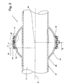
- die Vorrichtung gemäß Figur 1, entlang der Schnittlinie II - II,
- Figur 3
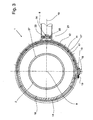
- die Vorrichtung gemäß Figur 2 entlang der Schnittlinie III - III, und
- Figur 4
- eine vergrößerte Teilansicht der Vorrichtung aus Figur 2 im Bereich IV.
- In Figur 1 ist eine Vorrichtung 1 dargestellt, durch die ein medizinisches Gerät 2, durch das beispielsweise Stoßwellen zur Zertrümmerung von Nierensteinen oder zur Bildung von Knochenwachstum oder zur Wundheilung erzeugt werden können. Die von dem Gerät 2 generierten Stoßwellen sollen durch ein Membranbalg 3 unmittelbar in ein schematisch dargestelltes Behandlungszentrum 4 gelangen, das im Inneren eines nicht dargestellten Patienten liegt. Der Membranbalg 3 berührt die Haut des Patienten oder ist von diesem beabstandet angeordnet. Das medizinische Gerät 2 kann auch als Röntgengerät oder dgl. ausgebildet und von dem Behandlungszentrum 4 oder dem Patienten beabstandet angeordnet sein.
- Das Gerät 2 ist über einen L-förmig ausgebildeten Arm 6 an einer als Wagen ausgestalteten Halteeinrichtung 5 angebracht. Die Halteeinrichtung 5 ist demnach entlang eines Untergrundes verfahrbar. Der L-förmig ausgebildete Arm 6 besteht aus einem zwischen den Schenkeln des Armes 6 angeordneten Drehgelenk 7, so dass der Arm 6 um 360° in Bezug auf die Halteeinrichtung 5 verschwenkbar ist. Darüber hinaus kann das Drehgelenk 7 entlang des vertikalen Schenkels des Armes 6 höhenverstellbar verfahren werden.
- Am freien Ende des Armes 6 ist ein Drehgelenk 21 vorgesehen, das nachfolgend noch näher erläutert wird. An dem Drehgelenk 21 ist ein Aufnahmekörper 11 angebracht, der in seiner Gesamtheit einen vollständig geschlossenen Ring bildet. Zu Montage- bzw. Demontagezwecken ist der Aufnahmekörper 11 zweiteilig ausgebildet. Ferner kann der Aufnahmekörper 11 als offener Ring ausgestaltet sein, der jedoch mindestens einen Ringabschnitt von 185° aufweist.
- Das Gerät 2 besteht im Wesentlichen aus einem Gehäuse, das eine zylinderförmige Mantelfläche 27 aufweist. Etwa im geometrischen Zentrum 20 des Gerätes 2 ist eine kugelkalottenförmige Außenmantelfläche 13 vorgesehen, die vollständig oder teilweise von dem Aufnahmekörper 11 umgriffen ist. Durch den Aufnahmekörper 11 wird demnach das Gerät 2 an der Halteeinrichtung 5 derart abgestützt, dass das Gerät 2 relativ zu dem Aufnahmekörper 11 beweglich ist.
- Den Figuren 2 und 4 kann entnommen werden, dass der Aufnahmekörper 11 eine konzentrisch gekrümmte Innenseite 12 aufweist, die zu der Außenmantelfläche 13 beabstandet verläuft. Zwischen diesen beiden Flächen soll ein konstanter Abstand vorliegen, um ein Gleit- oder Wälzlager unterzubringen, durch das das Gerät 2 verschwenkbar am Aufnahmekörper 11 abgestützt ist.
- An der Innenseite 12 des Aufnahmekörpers 11 sind zwei Ringe 14 und 15 eingesetzt, in denen wiederum eine Vielzahl von Kugeln 16 drehbar angeordnet sind. Die Ringe 14 und 15 bilden demnach zusammen mit den Kugeln 16 zwei zueinander beabstandete Wälzlager, durch die die Außenmantelfläche 13 verschwenkbar gehalten ist, ohne dass das Gehäuse 2 aus dem Aufnahmekörper 11 in Richtung dessen Längsachse 9 herausgezogen werden kann. In ähnlich konstruktiver Weise können ein oder zwei Gleitlager im Inneren des Aufnahmekörpers 11 untergebracht sein. Die Längsachse 9 entspricht dabei der Z-Achse des in Figur 1 dargestellten Koordinatensystems; durch die von der x-und der y-Achse gebildeten Ebene wird die Bewegungsmöglichkeit des Gerätes 2 bzw. des Membranbalges 3 definiert.
- Der Abstand zwischen der Innenseite 12 und der Außenmantelfläche 13 entspricht dem Kugelradius der Kugeln 16. Des Weiteren liegen die Kugeln 16 senkrecht auf der Außenmantelfläche 13 an, und zwar unabhängig von der Winkelstellung der Außenmantelfläche 13 in Bezug auf den Aufnahmekörper 11.
- Des Weiteren ist der Innenseite 12 des Aufnahmekörpers 11 eine Bremse 17 zugeordnet, die in dem Aufnahmekörper 11 ortsfest gehalten ist und etwa mittig zwischen den beiden Ringen 14 und 15 verläuft. Die Bremse 17 wirkt auf die Außenmantelfläche 13 derart ein, dass die Bewegung des Gerätes 2 durch in die Bremse 17 eingesetzte Bremsglieder 17 festgestellt wird. Zu diesem Zweck ist die Bremse 17 aus zwei Halteringen zusammengesetzt, deren freie gegenüberliegende Enden durch ein Stellglied 18 zusammengehalten sind.
- In Figur 3 ist die Funktionsweise des Stellgliedes 18 dargestellt, das über einen Winkelhebel mit den beiden freien Enden der Bremse 17 verbunden ist. Durch Bewegen des Stellgliedes 18 in Richtung des Gerätes 2 werden somit die beiden freien Ende aufgrund des vorhandenen Winkelhebels auseinandergedrückt und folglich vergrößert sich der Innendurchmesser der Bremse 17, wodurch die Reibkraft auf die Außenmantelfläche 13 reduziert wird bzw, gänzlich entfällt. Die Bremsglieder 17' sind folglich von der Außenmantelfläche 13 beabstandet angeordnet. Damit kann das Gerät 2 relativ zu dem Aufnahmekörper 11 bewegt werden. Durch Bewegen des Stellgliedes 18 wird des Weiteren eine Rückstellfeder 19 zusammengedrückt. Wird nunmehr das Stellglied 18 losgelassen, drückt die Rückstellfeder 19 die beiden freien Enden der Bremse 17 zusammen, so dass erneut eine Bremskraft durch die Bremsglieder 17' auf die Außenmantelfläche 13 einwirkt und daher eine Bewegung des Gerätes 2 relativ zu dem Aufnahmekörper 11 nicht oder nur mit erheblichem Kraftaufwand möglich ist.
- Des Weiteren ist der Figur 3 zu entnehmen, dass der Aufnahmekörper 11 über das Drehgelenk 21, das in Form einer Schwalbenschwanzführung 22 ausgebildet ist, verbunden ist. Der eine Schenkel des Armes 6 ist dabei aus zwei teleskopartig ineinander verschieblichen Streben 8 aufgebaut. Zu Montagezwecken können die Streben 8 voneinander gelöst werden, so dass das Innere der dem Aufnahmekörper 11 zugeordnete Teilbereich von außen zugänglich ist. Zur Abdeckung der Schwalbenschwanzführung 22 ist ein Deckel 23 vorgesehen, der durch eine im Inneren der Strebe 8 angeordnete Schraube 24 arretierbar ist. Somit kann der Aufnahmekörper 11 senkrecht um die Längsachse der Strebe 8 aufgrund des vorhandenen Drehgelenkes 21 bewegt werden.
- Insbesondere der Figur 1 kann entnommen werden, in welchen Richtungen das Gerät 2 räumlich ausrichtbar ist. Zur manuellen Bedienbarkeit sind dabei an dem Gerät 2 zwei gegenüberliegende Haltegriffe 25 vorgesehen.
- Das Gerät 2 kann um das Drehgelenk 21, also um die Längsachse der Streben 8, in vertikaler Richtung bewegt werden. Des Weiteren ist das Gerät 2 in einer Ebene, die parallel zu der Längsachse der Streben 8 verläuft, ausrichtbar, denn die Außenmantelfläche 13 kann innerhalb des Aufnahmekörpers 11 bewegt werden, und zwar so lange, bis die Zylindermantelfläche 27, die im Bereich der Außenmantelfläche 13 verläuft, als Anschlag 28 an der Stirnseite des Aufnahmekörpers 11 anliegt.
- Im gewählten Ausführungsbeispiel sind die geometrischen Verhältnisse zwischen dem Durchmesser der Außenmantelfläche 13 und dem Innendurchmesser des Aufnahmekörpers 11 derart gewählt, dass ein Verstellwinkel α von +/- 26° um das Zentrum 20 des Gerätes 2 möglich ist. Hierbei handelt es sich um einen ersten Teilabschnitt des Verstellwinkels α. Ein zweiter Teilabschnitt des Verstellwinkels α wird über die Drehmöglichkeiten des Drehgelenkes 21 generiert. Die Auslenkung in vertikaler Richtung, also in der Ebene, die senkrecht zu der Längsachse 9 des Gerätes 2 verläuft, beträgt etwa +/- 45°.
- Aufgrund des konstruktiven Aufbaus der Vorrichtung 1 ist es nunmehr möglich, dass der Patient bzw. dessen Behandlungszentrum 4 ortsfest und stationär verbleibt. Das Gerät 2 kann ohne dass das Behandlungszentrum 4 zu bewegen ist, exakt zu diesem positioniert werden. Hierfür ist ein Bildschirm 26 mit einem nicht dargestellten Ortungs- und Navigationssystem vorgesehen, durch das der behandelnde Arzt die Möglichkeit erhält, die Ausrichtung des Gerätes 2 in Bezug auf das Behandlungszentrum 4 permanent zu überwachen.
Claims (17)
- Vorrichtung (1) zur räumlichen Positionierung eines, insbesondere medizinisch einsetzbaren, Gerätes (2), das mittels eines Armes (6) an einer Halteeinrichtung (5) oder dgl. verschwenkbar abgestützt ist,
dadurch gekennzeichnet,
dass an dem freien Ende des Armes (6) ein ringförmig ausgebildeter Aufnahmekörper (11) angebracht ist, dass an dem Gerät (2) eine kugelkalottenförmig gestaltete Außenmantelfläche (13) vorgesehen ist, die von dem Aufnahmekörper (11) ganz oder teilweise umgriffen ist, und dass die Außenmantelfläche (13) des Gerätes (2) relativ zu dem Aufnahmekörper (11) verschwenkbar in diesem gehalten ist. - Vorrichtung nach Anspruch 1,
dadurch gekennzeichnet,
dass die Innenseite (12) des Aufnahmekörpers (11) beabstandet zu der Außenmantelfläche (13) angeordnet ist, dass die Innenseite (12) konzentrisch zu der Außenmantelfläche (13) verläuft und dass zwischen dem Aufnahmekörper (11) und an diesem abgestützt mindestens ein Gleit- oder ein Wälzlager (13, 15, 16) vorgesehen ist, das auf die Außenmantelfläche (13) einwirkt. - Vorrichtung nach Anspruch 2,
dadurch gekennzeichnet,
dass das Wälzlager aus zwei Ringen (14, 15) besteht, die im Inneren des Aufnahmekörpers (11) fest angebracht und beabstandet zueinander ausgerichtet sind, dass die zwei Ringe (14, 15) parallel zueinander und senkrecht zu der Längsachse des Gerätes (2) verlaufen, dass in den beiden Ringen (14, 15) jeweils eine Vielzahl von aus diesen abstehenden Rollkörpem, die vorzugsweise in Form von Kugeln (16) ausgestattet sind, eingesetzt sind, die auf der Außenmantelfläche (13) des Gerätes (2) aufliegen, und dass die Rollkörper (16) drehbar in dem jeweiligen Ring (14, 15) gelagert sind. - Vorrichtung nach Anspruch 3,
dadurch gekennzeichnet,
dass die beiden Ringe (14, 15) im Bereich der beiden Stirnseiten des Aufnahmekörpers (11) angeordnet sind, und dass die Krümmung der Ringe (14, 15) konzentrisch zu der Außenmantelfläche (13) verläuft. - Vorrichtung nach Anspruch 4,
dadurch gekennzeichnet,
dass jeder der Rollkörper (16) senkrecht auf der Außenmantelfläche (13) des Gerätes (2) aufliegt. - Vorrichtung nach einem oder mehreren der vorgenannten Ansprüche,
dadurch gekennzeichnet,
dass zwischen dem Aufnahmekörper (11) und dem Arm (6) ein Drehgelenk (21) angeordnet ist, durch das das Gerät (2) senkrecht zu der von dem Arm (6) gebildeten Achse (10) beweglich ausrichtbar ist. - Vorrichtung nach Anspruch 6,
dadurch gekennzeichnet,
dass das Drehgelenk (21) aus zwei drehbar ineinander gelagerten Führungsgliedern (22, 23) besteht, die vorzugsweise in Form einer Schwalbenschwanzführung (22) miteinander verbunden sind. - Vorrichtung nach Anspruch 7,
dadurch gekennzeichnet,
dass die Öffnungen in der Schwalbenschwanzführung (22) durch einen Deckel (23) oder dgl. in Richtung der Längsachse (10) des Armes (6) verschlossen sind. - Vorrichtung nach einem oder mehreren der vorgenannten Ansprüche,
dadurch gekennzeichnet,
dass im Inneren des Aufnahmekörpers (11) eine von außen bedienbare Bremse (17) vorgesehen ist, die auf der Außenmantelfläche (13) anliegt und auf diese einstellbar einwirkt. - Vorrichtung nach Anspruch 9,
dadurch gekennzeichnet,
dass die Bremse (17) aus einem zweiteiligen Ring besteht, der die Außenmantelfläche (13) vollständig umgreift und dessen beiden freien Enden von außen mittels eines Stellgliedes (18) auseinander drückbar sind und dass die beiden freien Enden der Bremse (17) mittels einer Rückstellfeder (19) zusammengepresst sind. - Vorrichtung nach Anspruch 9 oder 10,
dadurch gekennzeichnet,
dass die Bremse (17) in der Mittelebne des Aufnahmekörpers (11) angeordnet ist. - Vorrichtung nach einem oder mehreren der vorgenannten Ansprüche,
dadurch gekennzeichnet,
dass der Arm (6) aus zwei teleskopartig ineinander verschiebbaren Stützstreben (8) gebildet ist. - Vorrichtung nach einem oder mehreren der vorgenannten Ansprüche,
dadurch gekennzeichnet,
dass zur manuellen Ausrichtung des Gerätes (2) an diesem ein oder mehrere Haltegriffe (25) vorgesehen ist bzw. sind. - Vorrichtung nach einem oder mehreren der vorgenannten Ansprüche,
dadurch gekennzeichnet,
dass die Oberfläche des Gerätes (2), die parallel zu dessen Längsachse (9) und im Bereich der Außenmantelfläche (13) verläuft, als Anschlag (28) für die Bewegungsfreiheit des Gerätes (2) dient. - Vorrichtung nach einem oder mehreren der vorgenannten Ansprüche,
dadurch gekennzeichnet,
dass die Außenmantelfläche (13) derart beschaffen ist, dass die Rollkörper (16) auf dieser möglichst reibungsarm abrollen. - Vorrichtung nach einem oder mehreren der vorgenannten Ansprüche,
dadurch gekennzeichnet,
dass das Gerät (2) in einer ersten Ebene, die senkrecht zu der Längsachse (9) des Gerätes verläuft, in einem Verstellwinkel (α) von +/- 26° und in einer zweiten Ebene, die senkrecht zu der ersten Ebene verläuft in einem Verstellwinkel (β) von +/- 45° beweglich ist. - Vorrichtung nach Anspruch 16,
dadurch gekennzeichnet,
dass der Verstellwinkel (β) in zwei unterschiedlichen Verstell-Abschnitten aufgeteilt ist.
Applications Claiming Priority (1)
| Application Number | Priority Date | Filing Date | Title |
|---|---|---|---|
| DE102006050781A DE102006050781A1 (de) | 2006-10-27 | 2006-10-27 | Vorrichtung zur räumlichen Positionierung eines Gerätes |
Publications (2)
| Publication Number | Publication Date |
|---|---|
| EP1915964A1 true EP1915964A1 (de) | 2008-04-30 |
| EP1915964B1 EP1915964B1 (de) | 2010-12-01 |
Family
ID=38972985
Family Applications (1)
| Application Number | Title | Priority Date | Filing Date |
|---|---|---|---|
| EP07020688A Not-in-force EP1915964B1 (de) | 2006-10-27 | 2007-10-23 | Vorrichtung zur räumlichen Positionierung eines Gerätes |
Country Status (4)
| Country | Link |
|---|---|
| US (1) | US7871047B2 (de) |
| EP (1) | EP1915964B1 (de) |
| AT (1) | ATE489910T1 (de) |
| DE (2) | DE102006050781A1 (de) |
Families Citing this family (4)
| Publication number | Priority date | Publication date | Assignee | Title |
|---|---|---|---|---|
| DE102005017724A1 (de) * | 2005-04-15 | 2006-11-09 | Ast Gmbh | Fokussiereinrichtung für eine Vorrichtung zur Erzeugung von Stoßwellen |
| EP3167838B1 (de) * | 2015-11-13 | 2021-02-17 | Ondal Medical Systems GmbH | Drehbare verbindung mit einem bremsungsmechanismus |
| US11867191B2 (en) * | 2019-08-01 | 2024-01-09 | Saudi Arabian Oil Company | Aerodynamic anti-rotation device |
| CN115596952A (zh) * | 2022-10-10 | 2023-01-13 | 四川大学华西医院(Cn) | 一种体外冲击波治疗仪机头固定装置 |
Citations (8)
| Publication number | Priority date | Publication date | Assignee | Title |
|---|---|---|---|---|
| US2659953A (en) * | 1951-10-12 | 1953-11-24 | Theodore A Woolsey | Coupling clamp with constant spring loading |
| US3783262A (en) * | 1973-04-03 | 1974-01-01 | Us Army | Portable surgical lamp |
| GB2074337A (en) * | 1980-04-15 | 1981-10-28 | Univ Technology | Adjustable support for an optical or other instrument |
| DE3427001C1 (de) | 1984-07-21 | 1986-02-06 | Dornier System Gmbh, 7990 Friedrichshafen | Ortungs- und Positioniervorrichtung |
| US5810712A (en) * | 1996-09-27 | 1998-09-22 | Ohio Medical Instrument Company, Inc. | Surgical endoscope support and pivot |
| US20030202841A1 (en) * | 2002-04-26 | 2003-10-30 | Hiroshi Marunaka | Ball joint with spherical rollers |
| EP1649818A2 (de) | 2004-10-22 | 2006-04-26 | Ethicon Endo-Surgery, Inc. | Führungsinstrument für die Benutzung mit einem Bilderzeugungssystem |
| WO2007085953A1 (en) * | 2006-01-26 | 2007-08-02 | Nanyang Technological University | Apparatus and method for motorised placement of needle |
Family Cites Families (33)
| Publication number | Priority date | Publication date | Assignee | Title |
|---|---|---|---|---|
| US4276779A (en) * | 1979-03-29 | 1981-07-07 | Raytheon Company | Dynamically focussed array |
| DE3146626C2 (de) * | 1981-11-25 | 1985-10-10 | Dornier System Gmbh, 7990 Friedrichshafen | Vorrichtung zum Zerstören von im Körper eines Lebewesens befindlichen Konkrementen |
| US4537074A (en) * | 1983-09-12 | 1985-08-27 | Technicare Corporation | Annular array ultrasonic transducers |
| EP0209053A3 (de) * | 1985-07-18 | 1987-09-02 | Wolfgang Prof. Dr. Eisenmenger | Verfahren und Einrichtung zur berührungsfreien Zertrümmerung von Konkrementen im Körper von Lebewesen |
| US4984575A (en) * | 1987-04-16 | 1991-01-15 | Olympus Optical Co., Ltd. | Therapeutical apparatus of extracorporeal type |
| DE3803275A1 (de) * | 1988-02-04 | 1989-08-17 | Dornier Medizintechnik | Piezoelektrische stosswellenquelle |
| DE3907605C2 (de) * | 1989-03-09 | 1996-04-04 | Dornier Medizintechnik | Stosswellenquelle |
| DE4039408A1 (de) | 1989-12-22 | 1991-06-27 | Siemens Ag | Stosswellengenerator mit einem reflektor |
| DE4007669C3 (de) * | 1990-03-10 | 1997-11-13 | Wolf Gmbh Richard | Vorrichtung zur Stoßwellenbehandlung |
| DE4113697A1 (de) * | 1991-04-26 | 1992-11-05 | Dornier Medizintechnik | Vorrichtung zur fokalbereichsortung fuer die lithotripsie |
| DE4211274C1 (en) * | 1992-04-03 | 1993-04-15 | Siemens Ag, 8000 Muenchen, De | Medical treatment unit e.g. for bone fractures - produces marking on monitor to indicate different positions of radiation beam in region to be treated |
| DE4212809C2 (de) * | 1992-04-16 | 1996-08-14 | Siemens Ag | Therapieeinrichtung zur Behandlung eines Lebewesens mit fokussierten akustischen Wellen |
| FR2690719B1 (fr) * | 1992-04-30 | 1996-06-07 | Jean Lemasson | Capot de protection d'un palier de roulement d'un arbre, notamment d'un tambour de convoyeur. |
| DE4229630C2 (de) * | 1992-09-04 | 1994-06-16 | Siemens Ag | Akustische Linse |
| DE4241161C2 (de) * | 1992-12-07 | 1995-04-13 | Siemens Ag | Akustische Therapieeinrichtung |
| DE4244218C1 (de) * | 1992-12-24 | 1994-04-07 | Hans Heuser | Friktionswickelwelle |
| DE4315282C2 (de) * | 1993-05-07 | 1999-10-07 | Siemens Ag | Verwendung einer akustischen Druckimpulsquelle |
| US5595178A (en) * | 1994-10-02 | 1997-01-21 | Hmt High Medical Technologies Gmbh | System, method and apparatus for treatment of degenerative bone |
| DE19548000C1 (de) * | 1995-12-21 | 1997-07-10 | Dornier Medizintechnik | Vorrichtung zur Ortung von Konkrementen im Körper eines Patienten |
| US6128575A (en) * | 1998-06-10 | 2000-10-03 | Hughes Electrnoics Corporation | Methods for accurately inserting satellite constellations into common orbit planes |
| DE19841951C2 (de) * | 1998-09-14 | 2002-08-29 | Storz Medical Ag Kreuzlingen | Verfahren zur Visualisierung der Ausrichtung von therapeutischen Schallwellen auf einen zu behandelnden bzw. zu bearbeitenden Bereich |
| US6755796B2 (en) * | 1999-02-07 | 2004-06-29 | Medispec Ltd. | Pressure-pulse therapy apparatus |
| US6306089B1 (en) * | 1999-09-24 | 2001-10-23 | Atl Ultrasound, Inc. | Ultrasonic diagnostic imaging system with customized measurements and calculations |
| DE10065450B4 (de) | 2000-12-27 | 2005-05-04 | Schwarze, Werner, Dr. | Vorrichtung zur Erzeugung von Stoßwellen |
| US6434216B1 (en) * | 2001-03-16 | 2002-08-13 | Ge Medical Systems Global Technology Company, Llc | Source pin loader method and apparatus for positron emission tomography |
| DE10158519B4 (de) * | 2001-11-29 | 2005-01-13 | Dornier Medtech Holding International Gmbh | Stoß- und Druckwellen-Therapiegerät |
| DE10160532C1 (de) * | 2001-12-10 | 2003-06-26 | Dornier Medizintechnik | Verfahren und Vorrichtung zur dreidimensionalen Ortung eines Konkrements |
| US6695270B1 (en) * | 2002-08-15 | 2004-02-24 | Ole Falk Smed | Flat panel display system |
| DE10304435B3 (de) | 2003-02-04 | 2004-07-15 | Dornier Medtech Systems Gmbh | Linsensystem für einen Stoßwellengenerator |
| FR2872580B1 (fr) | 2004-06-30 | 2006-09-01 | Valeo Equip Electr Moteur | Procede de mesure du courant electrique dans une pluralite de conducteurs |
| DE102005017724A1 (de) | 2005-04-15 | 2006-11-09 | Ast Gmbh | Fokussiereinrichtung für eine Vorrichtung zur Erzeugung von Stoßwellen |
| US7207714B1 (en) * | 2006-05-26 | 2007-04-24 | Harkeerat Dhillon | Extensible positioning and targeting apparatus for a beam emitting source |
| US7610079B2 (en) * | 2006-07-25 | 2009-10-27 | Ast Gmbh | Shock wave imaging system |
-
2006
- 2006-10-27 DE DE102006050781A patent/DE102006050781A1/de not_active Withdrawn
-
2007
- 2007-10-23 AT AT07020688T patent/ATE489910T1/de active
- 2007-10-23 EP EP07020688A patent/EP1915964B1/de not_active Not-in-force
- 2007-10-23 DE DE502007005821T patent/DE502007005821D1/de active Active
- 2007-10-25 US US11/924,398 patent/US7871047B2/en not_active Expired - Fee Related
Patent Citations (8)
| Publication number | Priority date | Publication date | Assignee | Title |
|---|---|---|---|---|
| US2659953A (en) * | 1951-10-12 | 1953-11-24 | Theodore A Woolsey | Coupling clamp with constant spring loading |
| US3783262A (en) * | 1973-04-03 | 1974-01-01 | Us Army | Portable surgical lamp |
| GB2074337A (en) * | 1980-04-15 | 1981-10-28 | Univ Technology | Adjustable support for an optical or other instrument |
| DE3427001C1 (de) | 1984-07-21 | 1986-02-06 | Dornier System Gmbh, 7990 Friedrichshafen | Ortungs- und Positioniervorrichtung |
| US5810712A (en) * | 1996-09-27 | 1998-09-22 | Ohio Medical Instrument Company, Inc. | Surgical endoscope support and pivot |
| US20030202841A1 (en) * | 2002-04-26 | 2003-10-30 | Hiroshi Marunaka | Ball joint with spherical rollers |
| EP1649818A2 (de) | 2004-10-22 | 2006-04-26 | Ethicon Endo-Surgery, Inc. | Führungsinstrument für die Benutzung mit einem Bilderzeugungssystem |
| WO2007085953A1 (en) * | 2006-01-26 | 2007-08-02 | Nanyang Technological University | Apparatus and method for motorised placement of needle |
Also Published As
| Publication number | Publication date |
|---|---|
| ATE489910T1 (de) | 2010-12-15 |
| DE102006050781A1 (de) | 2008-04-30 |
| EP1915964B1 (de) | 2010-12-01 |
| US7871047B2 (en) | 2011-01-18 |
| DE502007005821D1 (de) | 2011-01-13 |
| US20090014607A1 (en) | 2009-01-15 |
Similar Documents
| Publication | Publication Date | Title |
|---|---|---|
| DE19746956C2 (de) | Medizinisches System aufweisend ein Röntgengerät und ein Therapiegerät mit einer Quelle fokussierter akustischer Wellen | |
| DE102008032294A1 (de) | Röntgeneinrichtung | |
| EP2982880A2 (de) | Vorrichtung zum selbsthemmenden bidirektionalen antrieb einer medizinischen behandlungsvorrichtung | |
| DE3724816A1 (de) | Kugellagerverbindung | |
| DE2744509A1 (de) | Abstuetzvorrichtung | |
| EP0699419A2 (de) | Osteosynthetischer Fixateur | |
| EP1915964B1 (de) | Vorrichtung zur räumlichen Positionierung eines Gerätes | |
| EP1720467B1 (de) | Anlage zur bildgestützten stosswellenbehandlung | |
| DE4135328C2 (de) | Extrakorporales Therapiegerät | |
| DE102015207736B4 (de) | Mobiles C-Bogen-Röntgengerät | |
| DE102004010004B4 (de) | Anlage zur nichtinvasiven medizinischen Behandlung | |
| DE2500958B2 (de) | Fraeswerkzeug zur aufbereitung des pfannenlagers bei totalprothetischem hueftgelenkersatz | |
| EP0739609B1 (de) | Lithotripsievorrichtung | |
| DE102005056698B4 (de) | Medizinische Strahlentherapieeinrichtung mit verschiebbarer Position des Strahlaustrittsfensters | |
| DE3101865C2 (de) | ||
| EP2105098B1 (de) | Druckwellentherapievorrichtung mit integrierter Röntgenanlage | |
| EP1095625B1 (de) | Haltesystem für Hilfsinstrumente insbesondere in der minimal invasiven Chirurgie | |
| DE10236177B4 (de) | Lithotripter | |
| DE102016121201B4 (de) | Orthese | |
| DE102010007334B4 (de) | Beinhalteranordnung für ein medizinisches Untersuchungs- oder Behandlungsgerät, Patientenlagerungsvorrichtung mit einer Beinhalteranordnung und Verwendung einer derartigen Patientenlagerungsvorrichtung | |
| EP1506744B1 (de) | Lithotripter | |
| DE10236176B4 (de) | Lithotripter | |
| DE10303462B4 (de) | Lithotripter | |
| DE19512957A1 (de) | Kinematik für medizintechnische Geräte | |
| WO2003005922A1 (de) | Fixierungsring zur kopffixierung |
Legal Events
| Date | Code | Title | Description |
|---|---|---|---|
| PUAI | Public reference made under article 153(3) epc to a published international application that has entered the european phase |
Free format text: ORIGINAL CODE: 0009012 |
|
| AK | Designated contracting states |
Kind code of ref document: A1 Designated state(s): AT BE BG CH CY CZ DE DK EE ES FI FR GB GR HU IE IS IT LI LT LU LV MC MT NL PL PT RO SE SI SK TR |
|
| AX | Request for extension of the european patent |
Extension state: AL BA HR MK RS |
|
| 17P | Request for examination filed |
Effective date: 20081017 |
|
| 17Q | First examination report despatched |
Effective date: 20081125 |
|
| AKX | Designation fees paid |
Designated state(s): AT BE BG CH CY CZ DE DK EE ES FI FR GB GR HU IE IS IT LI LT LU LV MC MT NL PL PT RO SE SI SK TR |
|
| GRAP | Despatch of communication of intention to grant a patent |
Free format text: ORIGINAL CODE: EPIDOSNIGR1 |
|
| GRAS | Grant fee paid |
Free format text: ORIGINAL CODE: EPIDOSNIGR3 |
|
| GRAA | (expected) grant |
Free format text: ORIGINAL CODE: 0009210 |
|
| AK | Designated contracting states |
Kind code of ref document: B1 Designated state(s): AT BE BG CH CY CZ DE DK EE ES FI FR GB GR HU IE IS IT LI LT LU LV MC MT NL PL PT RO SE SI SK TR |
|
| REG | Reference to a national code |
Ref country code: GB Ref legal event code: FG4D Free format text: NOT ENGLISH |
|
| REG | Reference to a national code |
Ref country code: CH Ref legal event code: EP |
|
| REG | Reference to a national code |
Ref country code: IE Ref legal event code: FG4D |
|
| REF | Corresponds to: |
Ref document number: 502007005821 Country of ref document: DE Date of ref document: 20110113 Kind code of ref document: P |
|
| REG | Reference to a national code |
Ref country code: NL Ref legal event code: VDEP Effective date: 20101201 |
|
| PG25 | Lapsed in a contracting state [announced via postgrant information from national office to epo] |
Ref country code: LT Free format text: LAPSE BECAUSE OF FAILURE TO SUBMIT A TRANSLATION OF THE DESCRIPTION OR TO PAY THE FEE WITHIN THE PRESCRIBED TIME-LIMIT Effective date: 20101201 |
|
| LTIE | Lt: invalidation of european patent or patent extension |
Effective date: 20101201 |
|
| PG25 | Lapsed in a contracting state [announced via postgrant information from national office to epo] |
Ref country code: SI Free format text: LAPSE BECAUSE OF FAILURE TO SUBMIT A TRANSLATION OF THE DESCRIPTION OR TO PAY THE FEE WITHIN THE PRESCRIBED TIME-LIMIT Effective date: 20101201 Ref country code: BG Free format text: LAPSE BECAUSE OF FAILURE TO SUBMIT A TRANSLATION OF THE DESCRIPTION OR TO PAY THE FEE WITHIN THE PRESCRIBED TIME-LIMIT Effective date: 20110301 Ref country code: LV Free format text: LAPSE BECAUSE OF FAILURE TO SUBMIT A TRANSLATION OF THE DESCRIPTION OR TO PAY THE FEE WITHIN THE PRESCRIBED TIME-LIMIT Effective date: 20101201 Ref country code: SE Free format text: LAPSE BECAUSE OF FAILURE TO SUBMIT A TRANSLATION OF THE DESCRIPTION OR TO PAY THE FEE WITHIN THE PRESCRIBED TIME-LIMIT Effective date: 20101201 Ref country code: FI Free format text: LAPSE BECAUSE OF FAILURE TO SUBMIT A TRANSLATION OF THE DESCRIPTION OR TO PAY THE FEE WITHIN THE PRESCRIBED TIME-LIMIT Effective date: 20101201 Ref country code: CY Free format text: LAPSE BECAUSE OF FAILURE TO SUBMIT A TRANSLATION OF THE DESCRIPTION OR TO PAY THE FEE WITHIN THE PRESCRIBED TIME-LIMIT Effective date: 20101201 Ref country code: NL Free format text: LAPSE BECAUSE OF FAILURE TO SUBMIT A TRANSLATION OF THE DESCRIPTION OR TO PAY THE FEE WITHIN THE PRESCRIBED TIME-LIMIT Effective date: 20101201 |
|
| REG | Reference to a national code |
Ref country code: IE Ref legal event code: FD4D |
|
| PG25 | Lapsed in a contracting state [announced via postgrant information from national office to epo] |
Ref country code: GR Free format text: LAPSE BECAUSE OF FAILURE TO SUBMIT A TRANSLATION OF THE DESCRIPTION OR TO PAY THE FEE WITHIN THE PRESCRIBED TIME-LIMIT Effective date: 20110302 |
|
| PG25 | Lapsed in a contracting state [announced via postgrant information from national office to epo] |
Ref country code: ES Free format text: LAPSE BECAUSE OF FAILURE TO SUBMIT A TRANSLATION OF THE DESCRIPTION OR TO PAY THE FEE WITHIN THE PRESCRIBED TIME-LIMIT Effective date: 20110312 Ref country code: EE Free format text: LAPSE BECAUSE OF FAILURE TO SUBMIT A TRANSLATION OF THE DESCRIPTION OR TO PAY THE FEE WITHIN THE PRESCRIBED TIME-LIMIT Effective date: 20101201 Ref country code: PT Free format text: LAPSE BECAUSE OF FAILURE TO SUBMIT A TRANSLATION OF THE DESCRIPTION OR TO PAY THE FEE WITHIN THE PRESCRIBED TIME-LIMIT Effective date: 20110401 Ref country code: IE Free format text: LAPSE BECAUSE OF FAILURE TO SUBMIT A TRANSLATION OF THE DESCRIPTION OR TO PAY THE FEE WITHIN THE PRESCRIBED TIME-LIMIT Effective date: 20101201 Ref country code: CZ Free format text: LAPSE BECAUSE OF FAILURE TO SUBMIT A TRANSLATION OF THE DESCRIPTION OR TO PAY THE FEE WITHIN THE PRESCRIBED TIME-LIMIT Effective date: 20101201 Ref country code: IS Free format text: LAPSE BECAUSE OF FAILURE TO SUBMIT A TRANSLATION OF THE DESCRIPTION OR TO PAY THE FEE WITHIN THE PRESCRIBED TIME-LIMIT Effective date: 20110401 |
|
| PG25 | Lapsed in a contracting state [announced via postgrant information from national office to epo] |
Ref country code: SK Free format text: LAPSE BECAUSE OF FAILURE TO SUBMIT A TRANSLATION OF THE DESCRIPTION OR TO PAY THE FEE WITHIN THE PRESCRIBED TIME-LIMIT Effective date: 20101201 Ref country code: RO Free format text: LAPSE BECAUSE OF FAILURE TO SUBMIT A TRANSLATION OF THE DESCRIPTION OR TO PAY THE FEE WITHIN THE PRESCRIBED TIME-LIMIT Effective date: 20101201 Ref country code: PL Free format text: LAPSE BECAUSE OF FAILURE TO SUBMIT A TRANSLATION OF THE DESCRIPTION OR TO PAY THE FEE WITHIN THE PRESCRIBED TIME-LIMIT Effective date: 20101201 |
|
| PLBE | No opposition filed within time limit |
Free format text: ORIGINAL CODE: 0009261 |
|
| STAA | Information on the status of an ep patent application or granted ep patent |
Free format text: STATUS: NO OPPOSITION FILED WITHIN TIME LIMIT |
|
| PG25 | Lapsed in a contracting state [announced via postgrant information from national office to epo] |
Ref country code: DK Free format text: LAPSE BECAUSE OF FAILURE TO SUBMIT A TRANSLATION OF THE DESCRIPTION OR TO PAY THE FEE WITHIN THE PRESCRIBED TIME-LIMIT Effective date: 20101201 |
|
| 26N | No opposition filed |
Effective date: 20110902 |
|
| REG | Reference to a national code |
Ref country code: DE Ref legal event code: R097 Ref document number: 502007005821 Country of ref document: DE Effective date: 20110902 |
|
| BERE | Be: lapsed |
Owner name: AST G.M.B.H. Effective date: 20111031 |
|
| PG25 | Lapsed in a contracting state [announced via postgrant information from national office to epo] |
Ref country code: MC Free format text: LAPSE BECAUSE OF NON-PAYMENT OF DUE FEES Effective date: 20111031 |
|
| GBPC | Gb: european patent ceased through non-payment of renewal fee |
Effective date: 20111023 |
|
| PG25 | Lapsed in a contracting state [announced via postgrant information from national office to epo] |
Ref country code: BE Free format text: LAPSE BECAUSE OF NON-PAYMENT OF DUE FEES Effective date: 20111031 |
|
| PG25 | Lapsed in a contracting state [announced via postgrant information from national office to epo] |
Ref country code: GB Free format text: LAPSE BECAUSE OF NON-PAYMENT OF DUE FEES Effective date: 20111023 |
|
| PG25 | Lapsed in a contracting state [announced via postgrant information from national office to epo] |
Ref country code: MT Free format text: LAPSE BECAUSE OF FAILURE TO SUBMIT A TRANSLATION OF THE DESCRIPTION OR TO PAY THE FEE WITHIN THE PRESCRIBED TIME-LIMIT Effective date: 20101201 |
|
| PG25 | Lapsed in a contracting state [announced via postgrant information from national office to epo] |
Ref country code: LU Free format text: LAPSE BECAUSE OF NON-PAYMENT OF DUE FEES Effective date: 20111023 |
|
| PG25 | Lapsed in a contracting state [announced via postgrant information from national office to epo] |
Ref country code: TR Free format text: LAPSE BECAUSE OF FAILURE TO SUBMIT A TRANSLATION OF THE DESCRIPTION OR TO PAY THE FEE WITHIN THE PRESCRIBED TIME-LIMIT Effective date: 20101201 |
|
| PG25 | Lapsed in a contracting state [announced via postgrant information from national office to epo] |
Ref country code: HU Free format text: LAPSE BECAUSE OF FAILURE TO SUBMIT A TRANSLATION OF THE DESCRIPTION OR TO PAY THE FEE WITHIN THE PRESCRIBED TIME-LIMIT Effective date: 20101201 |
|
| REG | Reference to a national code |
Ref country code: AT Ref legal event code: MM01 Ref document number: 489910 Country of ref document: AT Kind code of ref document: T Effective date: 20121031 |
|
| REG | Reference to a national code |
Ref country code: DE Ref legal event code: R082 Ref document number: 502007005821 Country of ref document: DE Representative=s name: ENGELHARDT & ENGELHARDT PATENTANWAELTE, DE |
|
| PG25 | Lapsed in a contracting state [announced via postgrant information from national office to epo] |
Ref country code: AT Free format text: LAPSE BECAUSE OF NON-PAYMENT OF DUE FEES Effective date: 20121031 |
|
| REG | Reference to a national code |
Ref country code: CH Ref legal event code: NV Representative=s name: DIPL.-ING. G. ENGELHARDT, CH Ref country code: CH Ref legal event code: PUE Owner name: STORZ MEDICAL AG, CH Free format text: FORMER OWNER: AST GMBH, DE |
|
| REG | Reference to a national code |
Ref country code: DE Ref legal event code: R082 Ref document number: 502007005821 Country of ref document: DE Representative=s name: ENGELHARDT & ENGELHARDT PATENTANWAELTE, DE Effective date: 20140113 Ref country code: DE Ref legal event code: R081 Ref document number: 502007005821 Country of ref document: DE Owner name: STORZ MEDICAL AG, CH Free format text: FORMER OWNER: AST GMBH, 07745 JENA, DE Effective date: 20140113 |
|
| REG | Reference to a national code |
Ref country code: FR Ref legal event code: TP Owner name: STORZ MEDICAL AG, CH Effective date: 20140402 |
|
| REG | Reference to a national code |
Ref country code: FR Ref legal event code: PLFP Year of fee payment: 9 |
|
| PGFP | Annual fee paid to national office [announced via postgrant information from national office to epo] |
Ref country code: DE Payment date: 20151127 Year of fee payment: 9 Ref country code: IT Payment date: 20151026 Year of fee payment: 9 |
|
| PGFP | Annual fee paid to national office [announced via postgrant information from national office to epo] |
Ref country code: FR Payment date: 20151026 Year of fee payment: 9 |
|
| PGFP | Annual fee paid to national office [announced via postgrant information from national office to epo] |
Ref country code: CH Payment date: 20160125 Year of fee payment: 9 |
|
| REG | Reference to a national code |
Ref country code: DE Ref legal event code: R119 Ref document number: 502007005821 Country of ref document: DE |
|
| REG | Reference to a national code |
Ref country code: CH Ref legal event code: PL |
|
| REG | Reference to a national code |
Ref country code: FR Ref legal event code: ST Effective date: 20170630 |
|
| PG25 | Lapsed in a contracting state [announced via postgrant information from national office to epo] |
Ref country code: LI Free format text: LAPSE BECAUSE OF NON-PAYMENT OF DUE FEES Effective date: 20161031 Ref country code: DE Free format text: LAPSE BECAUSE OF NON-PAYMENT OF DUE FEES Effective date: 20170503 Ref country code: CH Free format text: LAPSE BECAUSE OF NON-PAYMENT OF DUE FEES Effective date: 20161031 Ref country code: FR Free format text: LAPSE BECAUSE OF NON-PAYMENT OF DUE FEES Effective date: 20161102 |
|
| PG25 | Lapsed in a contracting state [announced via postgrant information from national office to epo] |
Ref country code: IT Free format text: LAPSE BECAUSE OF NON-PAYMENT OF DUE FEES Effective date: 20161023 |