EP1916052A2 - System, Verfahren und Vorrichtung zur Verstärkung von reibrührverarbeiteten Verbindungen - Google Patents
System, Verfahren und Vorrichtung zur Verstärkung von reibrührverarbeiteten Verbindungen Download PDFInfo
- Publication number
- EP1916052A2 EP1916052A2 EP07117200A EP07117200A EP1916052A2 EP 1916052 A2 EP1916052 A2 EP 1916052A2 EP 07117200 A EP07117200 A EP 07117200A EP 07117200 A EP07117200 A EP 07117200A EP 1916052 A2 EP1916052 A2 EP 1916052A2
- Authority
- EP
- European Patent Office
- Prior art keywords
- weld
- workpieces
- strengthening material
- friction stir
- interface
- Prior art date
- Legal status (The legal status is an assumption and is not a legal conclusion. Google has not performed a legal analysis and makes no representation as to the accuracy of the status listed.)
- Withdrawn
Links
Images


Classifications
-
- B—PERFORMING OPERATIONS; TRANSPORTING
- B23—MACHINE TOOLS; METAL-WORKING NOT OTHERWISE PROVIDED FOR
- B23K—SOLDERING OR UNSOLDERING; WELDING; CLADDING OR PLATING BY SOLDERING OR WELDING; CUTTING BY APPLYING HEAT LOCALLY, e.g. FLAME CUTTING; WORKING BY LASER BEAM
- B23K20/00—Non-electric welding by applying impact or other pressure, with or without the application of heat, e.g. cladding or plating
- B23K20/12—Non-electric welding by applying impact or other pressure, with or without the application of heat, e.g. cladding or plating the heat being generated by friction; Friction welding
- B23K20/122—Non-electric welding by applying impact or other pressure, with or without the application of heat, e.g. cladding or plating the heat being generated by friction; Friction welding using a non-consumable tool, e.g. friction stir welding
- B23K20/123—Controlling or monitoring the welding process
- B23K20/1235—Controlling or monitoring the welding process with temperature control during joining
-
- B—PERFORMING OPERATIONS; TRANSPORTING
- B23—MACHINE TOOLS; METAL-WORKING NOT OTHERWISE PROVIDED FOR
- B23K—SOLDERING OR UNSOLDERING; WELDING; CLADDING OR PLATING BY SOLDERING OR WELDING; CUTTING BY APPLYING HEAT LOCALLY, e.g. FLAME CUTTING; WORKING BY LASER BEAM
- B23K20/00—Non-electric welding by applying impact or other pressure, with or without the application of heat, e.g. cladding or plating
- B23K20/12—Non-electric welding by applying impact or other pressure, with or without the application of heat, e.g. cladding or plating the heat being generated by friction; Friction welding
- B23K20/122—Non-electric welding by applying impact or other pressure, with or without the application of heat, e.g. cladding or plating the heat being generated by friction; Friction welding using a non-consumable tool, e.g. friction stir welding
- B23K20/1245—Non-electric welding by applying impact or other pressure, with or without the application of heat, e.g. cladding or plating the heat being generated by friction; Friction welding using a non-consumable tool, e.g. friction stir welding characterised by the apparatus
- B23K20/126—Workpiece support, i.e. backing or clamping
-
- B—PERFORMING OPERATIONS; TRANSPORTING
- B23—MACHINE TOOLS; METAL-WORKING NOT OTHERWISE PROVIDED FOR
- B23K—SOLDERING OR UNSOLDERING; WELDING; CLADDING OR PLATING BY SOLDERING OR WELDING; CUTTING BY APPLYING HEAT LOCALLY, e.g. FLAME CUTTING; WORKING BY LASER BEAM
- B23K20/00—Non-electric welding by applying impact or other pressure, with or without the application of heat, e.g. cladding or plating
- B23K20/12—Non-electric welding by applying impact or other pressure, with or without the application of heat, e.g. cladding or plating the heat being generated by friction; Friction welding
- B23K20/122—Non-electric welding by applying impact or other pressure, with or without the application of heat, e.g. cladding or plating the heat being generated by friction; Friction welding using a non-consumable tool, e.g. friction stir welding
- B23K20/128—Non-electric welding by applying impact or other pressure, with or without the application of heat, e.g. cladding or plating the heat being generated by friction; Friction welding using a non-consumable tool, e.g. friction stir welding making use of additional material
-
- B—PERFORMING OPERATIONS; TRANSPORTING
- B23—MACHINE TOOLS; METAL-WORKING NOT OTHERWISE PROVIDED FOR
- B23K—SOLDERING OR UNSOLDERING; WELDING; CLADDING OR PLATING BY SOLDERING OR WELDING; CUTTING BY APPLYING HEAT LOCALLY, e.g. FLAME CUTTING; WORKING BY LASER BEAM
- B23K33/00—Specially-profiled edge portions of workpieces for making soldering or welding connections; Filling the seams formed thereby
- B23K33/004—Filling of continuous seams
Definitions
- the present invention relates in general to friction stir processing and, in particular, to an improved system, method, and apparatus for reinforcing friction stir welded joints with a topically applied reinforcing substance.
- Friction stir welding involves the joining of metals without fusion or filler materials. It is typically used for the joining of structural components made of aluminum and its alloys. The process results in strong and ductile joints, sometimes in systems that have proved difficult using conventional welding techniques. The process is most suitable for components that are flat and long (e.g., plates and sheets), but can be adapted for pipes, hollow sections, and positional welding. The welds are created by the combined action of frictional heating and mechanical deformation due to a rotating tool. Friction stir welding is a solid state process as the maximum temperature reached is on the order of 80% of the melting temperature of the workpieces.
- the tool 11 typically used for friction stir welding has a body 13 with a circular cross-sectional shape.
- the distal or lower end of the body 13 has a short threaded pin or probe, or more complicated flute protruding therefrom.
- the junction between the cylindrical body 13 and the probe is known as the shoulder 15.
- the workpieces 17, 19 are abutted or otherwise engaged to define an interface 21.
- the probe is used to penetrate the workpieces 17, 19 at the interface 21, whereas the shoulder 15 rubs the top surfaces 18, 20 of the workpieces 17, 19, respectively.
- Heat is generated primarily by friction between the rotating and translating tool 11, again the shoulder 15 of which rubs against the top surfaces 18, 20 of the workpieces 17, 19, respectively.
- the welding parameters are adjusted so that the ratio of frictional to volumetric deformation-induced heating decreases as the workpiece becomes thicker. This adjustment is made to ensure a sufficient heat input per unit length.
- the microstructure of a friction stir weld 23 ( Figure 2) depends in detail on the tool design, the rotation and translation speeds, the applied pressure, and the characteristics of the materials being joined. There are a number of zones associated with the process.
- the heat affected zone (HAZ) 25 is analogous to that in conventional welds.
- the central nugget region 27 containing an onion ring-like flow pattern is the most severely deformed region, although it frequently seems to dynamically recrystallize so that the detailed microstructure may comprise equiaxed grains.
- This layered structure is a consequence of the way in which a threaded tool deposits material from the front to the back of the weld. Cylindrical sheets of material are extruded during each rotation of the tool, which on a weld cross-section give the characteristic onion ring appearance.
- thermomechanically-affected zone 29 lies directly between the heat affected zone 25 and central nugget region 27.
- the grains of the original microstructure of the workpieces 17, 19 are retained in this region 29 but in a deformed state.
- the top surface 24 of the weld 23 has a different microstructure, a consequence of the shearing induced by the rotating tool shoulder.
- the heat generated during welding causes precipitates in the weld nugget to redissolve. This lowers the strength of the weld with respect to the parent material.
- An aging heat treatment following the welding operation can restore the strength to the nugget.
- heat treatments tend to overage the parent material and cause a corresponding loss in desirable physical properties.
- One embodiment of a system, method, and apparatus for reinforcing friction stir processed (e.g., welded) joints utilizes a strengthening material that is applied directly to the joint surfaces to counteract the loss of desirable physical properties in the workpieces being joined.
- the strengthening material comprises a reinforcing substance at the bond interfaces that is stirred into the weld nugget during processing to form a more robust joint.
- the reinforcing substance is distributed throughout the nugget and counterbalances the loss of strength due to dissolution of precipitates during processing.
- the reinforcing substance may comprise many different forms, including a paste that is brushed onto the workpieces, a spray, a vapor coat, a sandwich foil, etc.
- the reinforcing substance is applied to the workpieces prior to processing by friction stir welding.
- Examples of materials that may be used to form the reinforcing substance include scandium-aluminum alloys, carbon nanotubes, ceramic materials, or still other materials capable of reestablishing or approximating the original strength of the parent materials prior to friction stir welding.
- Figure 1 is a schematic isometric view of a friction stir processing apparatus for joining workpieces
- Figure 2 is schematic sectional view of a weld formed by the process and apparatus of Figure 1;
- Figure 3 is a top view of workpieces prior to formation of a butt joint therebetween and having one embodiment of a reinforcing medium applied thereto in accordance with the present invention
- Figure 4 is a top view of workpieces prior to formation of a lap joint therebetween and having one embodiment of a reinforcing medium applied thereto in accordance with the present invention
- Figure 5 is a top view of workpieces prior to formation of a finger joint therebetween and having one embodiment of a reinforcing medium applied thereto in accordance with the present invention
- Figure 6 is schematic sectional view of one embodiment of a weld formed by a system, method, and apparatus in accordance with the present invention.
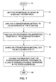
- Figure 7 is a high level flow diagram of one embodiment of a method in accordance with the present invention.
- Figures 3 - 6 one embodiment of a system, method, and apparatus for reinforcing a weld formed by friction stir welding is disclosed.
- at least two workpieces 31, 33 are abutted or otherwise engaged to define an interface 35 therebetween.
- Figure 3 depicts a butt joint, but other types of joints such as a lap joint 41 ( Figure 4), a finger joint 43 ( Figure 5), etc., also may be used.
- Each of the workpieces 31, 33 has a top surface 37, 39, respectively, upon which is applied a strengthening material 45.
- the strengthening material 45 may be applied directly to the top surfaces 37, 39 of the workpieces 31, 33, respectively, at the interface 35.
- the workpieces are friction stir welded together with a tool (e.g., described above) at the interface 35 to form a weld 51 ( Figure 6).
- the weld 51 may comprise a central weld nugget, a heat affected zone, and a thermomechanically-affected zone directly therebetween.
- the strengthening material 45 is stirred with the friction stir welding tool into the weld 51 during the friction stir welding process, such that the strengthening material 45 is distributed throughout the central weld nugget of weld 51.
- the strengthening material 45 counterbalances a loss of strength in the workpieces 31, 33 due to dissolution of precipitates during processing.
- the weld 51 is cooled such that the strengthening material 45 counteracts a loss of desirable physical properties in the joined workpieces 31, 33.
- the strengthening material acts as a reinforcing substance at bond interfaces in the weld 51 during processing to form a more robust joint.
- the presence of the strengthening material 45 in the weld 51 approximates an original strength of the workpieces prior to friction stir welding.
- the strengthening material may take the form of materials such as pastes, sprays, vapor coats, or sandwich foils.
- the strengthening material may comprise many different types of materials including, for example, scandium-aluminum alloys, carbon nanotubes, and ceramic materials.
- the method begins as indicated at step 71, and comprises abutting workpieces to define an interface therebetween (step 73); applying a strengthening material to the workpieces at the interface (step 75); friction stir processing the workpieces together at the interface to form a weld (step 77); mixing the strengthening material into the weld during step 77 (step 79); cooling the weld such that the strengthening material counteracts a loss of desirable physical properties in the joined workpieces (step 81); before ending as indicated at step 83.
- the method also may comprise using the strengthening material as a reinforcing substance at bond interfaces in the weld during processing to form a more robust joint.
- the method may further comprise evenly distributing the strengthening material throughout the weld and counterbalancing a loss of strength in the workpieces due to dissolution of precipitates during processing.
- the strengthening material may comprise a paste, a spray, a vapor coat, or a sandwich foil.
- the strengthening material may comprise scandium-aluminum alloys, carbon nanotubes, or ceramic materials. The presence of the strengthening material in the weld approximates an original strength of the workpieces prior to formation of the weld.
- a method of joining workpieces comprising:
- step (d) comprises using the strengthening material as a reinforcing substance at bond interfaces in the weld during processing to form a more robust joint.
- the strengthening material is selected from the group consisting of paste, spray, vapor coat, and sandwich foil.
- the strengthening material is selected from the group consisting of scandium-aluminum alloys, carbon nanotubes, and ceramic materials.
- weld comprises a central weld nugget, a heat affected zone, and a thermomechanically-affected zone directly therebetween.
- a method of reinforcing a weld formed by friction stir welding comprising:
- step (d) comprises using the strengthening material as a reinforcing substance at bond interfaces in the weld during processing to form a more robust joint.
- the strengthening material is selected from the group consisting of a paste, a spray, a vapor coat, and a sandwich foil.
- the strengthening material is selected from the group consisting of scandium-aluminum alloys, carbon nanotubes, and ceramic materials.
- weld comprises a central weld nugget, a heat affected zone, and a thermomechanically-affected zone directly therebetween.
- a method of reinforcing a weld formed by friction stir welding comprising:
- step (d) comprises using the strengthening material as a reinforcing substance at bond interfaces in the weld during processing to form a more robust joint.
- the strengthening material is selected from the group consisting of a paste, a spray, a vapor coat, and a sandwich foil.
- the strengthening material is selected from the group consisting of scandium-aluminum alloys, carbon nanotubes, ceramic materials.
Landscapes
- Engineering & Computer Science (AREA)
- Mechanical Engineering (AREA)
- Pressure Welding/Diffusion-Bonding (AREA)
Applications Claiming Priority (1)
| Application Number | Priority Date | Filing Date | Title |
|---|---|---|---|
| US11/586,292 US20080099534A1 (en) | 2006-10-25 | 2006-10-25 | System, method, and apparatus for reinforcing friction stir processed joints |
Publications (2)
| Publication Number | Publication Date |
|---|---|
| EP1916052A2 true EP1916052A2 (de) | 2008-04-30 |
| EP1916052A3 EP1916052A3 (de) | 2008-08-27 |
Family
ID=38984202
Family Applications (1)
| Application Number | Title | Priority Date | Filing Date |
|---|---|---|---|
| EP07117200A Withdrawn EP1916052A3 (de) | 2006-10-25 | 2007-09-25 | System, Verfahren und Vorrichtung zur Verstärkung von reibrührverarbeiteten Verbindungen |
Country Status (2)
| Country | Link |
|---|---|
| US (1) | US20080099534A1 (de) |
| EP (1) | EP1916052A3 (de) |
Cited By (1)
| Publication number | Priority date | Publication date | Assignee | Title |
|---|---|---|---|---|
| WO2008119446A1 (de) * | 2007-03-30 | 2008-10-09 | Eads Deutschland Gmbh | Verfahren zur herstellung nanoteilchen-verstärkter halbzeuge sowie danach hergestellte halbzeuge |
Families Citing this family (6)
| Publication number | Priority date | Publication date | Assignee | Title |
|---|---|---|---|---|
| US8261961B2 (en) * | 2008-04-10 | 2012-09-11 | Lockheed Martin Corporation | Metal matrix carbon nanotube composite material and method of making same |
| US10688592B1 (en) | 2017-09-05 | 2020-06-23 | United Launch Alliance L.L.C | Friction stir welding of aluminum alloys |
| WO2020072196A1 (en) * | 2018-10-03 | 2020-04-09 | Lam Research Corporation | Friction stir welding for ceramic applications |
| JP6698927B1 (ja) * | 2019-08-22 | 2020-05-27 | 株式会社フルヤ金属 | 金属系筒材の製造方法及びそれに用いられる裏当て治具 |
| CN112077433A (zh) * | 2020-07-20 | 2020-12-15 | 江西理工大学 | 一种提高fsw接头机械结合强度的方法 |
| US12576455B2 (en) | 2022-10-20 | 2026-03-17 | Standex International Corporation | Friction stir welding process for large metallic components |
Family Cites Families (4)
| Publication number | Priority date | Publication date | Assignee | Title |
|---|---|---|---|---|
| US6045028A (en) * | 1998-07-17 | 2000-04-04 | Mcdonnell Douglas Corporation | Integral corrosion protection of friction-welded joints |
| US6543670B2 (en) * | 2001-08-29 | 2003-04-08 | The Boeing Company | Interface preparation for weld joints |
| US6543671B2 (en) * | 2001-09-05 | 2003-04-08 | Lockheed Martin Corporation | Apparatus and method for friction stir welding using filler material |
| WO2005094541A2 (en) * | 2004-03-24 | 2005-10-13 | Smith International, Inc. | Solid state processing of materials through friction stir processing and friction stir mixing |
-
2006
- 2006-10-25 US US11/586,292 patent/US20080099534A1/en not_active Abandoned
-
2007
- 2007-09-25 EP EP07117200A patent/EP1916052A3/de not_active Withdrawn
Cited By (1)
| Publication number | Priority date | Publication date | Assignee | Title |
|---|---|---|---|---|
| WO2008119446A1 (de) * | 2007-03-30 | 2008-10-09 | Eads Deutschland Gmbh | Verfahren zur herstellung nanoteilchen-verstärkter halbzeuge sowie danach hergestellte halbzeuge |
Also Published As
| Publication number | Publication date |
|---|---|
| EP1916052A3 (de) | 2008-08-27 |
| US20080099534A1 (en) | 2008-05-01 |
Similar Documents
| Publication | Publication Date | Title |
|---|---|---|
| EP1916052A2 (de) | System, Verfahren und Vorrichtung zur Verstärkung von reibrührverarbeiteten Verbindungen | |
| Thomas | Friction stir welding and related friction process characteristics | |
| US5975406A (en) | Method to repair voids in aluminum alloys | |
| US7201811B2 (en) | Large diameter domes and methods of manufacturing same | |
| US6247633B1 (en) | Fabricating low distortion lap weld construction | |
| JP2792233B2 (ja) | 摩擦攪拌溶接 | |
| US7163136B2 (en) | Apparatus and method for friction stir welding utilizing a grooved pin | |
| US6676004B1 (en) | Tool for friction stir welding | |
| US7270257B2 (en) | Out-of-position friction stir welding of high melting temperature alloys | |
| US20050156010A1 (en) | Applications of friction stir welding using a superabrasive tool | |
| US10195686B2 (en) | Method for joining two essentially metal sheet-type workpieces using friction squeeze welding | |
| Martin et al. | Novel techniques for corner joints using friction stir welding | |
| Salamati et al. | Processing and tooling considerations in joining by forming technologies; part B—friction-based welding | |
| US11766738B2 (en) | Friction stir welding process | |
| EP3851238A1 (de) | Verfahren, produkt und vorrichtung | |
| US20040112872A1 (en) | Method for single sided spot welding | |
| JP2002224857A (ja) | 異種金属中空部材間の接合構造及びその接合方法 | |
| Smith et al. | Friction stir welding in the automotive industry | |
| JP2002096182A (ja) | 摩擦熱に基づく接合方法、回転ツール及び接合体 | |
| CN109848543A (zh) | 一种搅拌摩擦加工预防铝合金角接头层状撕裂的方法 | |
| CN108788442B (zh) | 一种金属管件的滚压摩擦连接方法 | |
| Suwarsono et al. | Mechanical properties of friction stir lap welding (FSLW) on dissimilar aluminum sheet A1100 and A1050 | |
| JPS61172684A (ja) | クラツド鋼管の製造方法 | |
| WANG et al. | 3 dimensional flow modeling of friction stir welding | |
| Dolby et al. | The joining of aluminium extrusions |
Legal Events
| Date | Code | Title | Description |
|---|---|---|---|
| PUAI | Public reference made under article 153(3) epc to a published international application that has entered the european phase |
Free format text: ORIGINAL CODE: 0009012 |
|
| AK | Designated contracting states |
Kind code of ref document: A2 Designated state(s): AT BE BG CH CY CZ DE DK EE ES FI FR GB GR HU IE IS IT LI LT LU LV MC MT NL PL PT RO SE SI SK TR |
|
| AX | Request for extension of the european patent |
Extension state: AL BA HR MK RS |
|
| PUAL | Search report despatched |
Free format text: ORIGINAL CODE: 0009013 |
|
| AK | Designated contracting states |
Kind code of ref document: A3 Designated state(s): AT BE BG CH CY CZ DE DK EE ES FI FR GB GR HU IE IS IT LI LT LU LV MC MT NL PL PT RO SE SI SK TR |
|
| AX | Request for extension of the european patent |
Extension state: AL BA HR MK RS |
|
| 17P | Request for examination filed |
Effective date: 20090211 |
|
| AKX | Designation fees paid |
Designated state(s): DE FR GB IT |
|
| 17Q | First examination report despatched |
Effective date: 20100423 |
|
| STAA | Information on the status of an ep patent application or granted ep patent |
Free format text: STATUS: THE APPLICATION IS DEEMED TO BE WITHDRAWN |
|
| 18D | Application deemed to be withdrawn |
Effective date: 20100401 |