EP1916169A2 - Soupape de frein de remorque avec adaptation de charge - Google Patents
Soupape de frein de remorque avec adaptation de charge Download PDFInfo
- Publication number
- EP1916169A2 EP1916169A2 EP07017256A EP07017256A EP1916169A2 EP 1916169 A2 EP1916169 A2 EP 1916169A2 EP 07017256 A EP07017256 A EP 07017256A EP 07017256 A EP07017256 A EP 07017256A EP 1916169 A2 EP1916169 A2 EP 1916169A2
- Authority
- EP
- European Patent Office
- Prior art keywords
- brake
- trailer brake
- piston
- trailer
- assembly
- Prior art date
- Legal status (The legal status is an assumption and is not a legal conclusion. Google has not performed a legal analysis and makes no representation as to the accuracy of the status listed.)
- Withdrawn
Links
- 238000005553 drilling Methods 0.000 abstract 1
- 230000000694 effects Effects 0.000 description 7
- 230000005540 biological transmission Effects 0.000 description 4
- 230000000903 blocking effect Effects 0.000 description 4
- 238000013519 translation Methods 0.000 description 3
- 230000014616 translation Effects 0.000 description 3
- 238000007789 sealing Methods 0.000 description 2
- 230000007704 transition Effects 0.000 description 2
- 230000006978 adaptation Effects 0.000 description 1
- 238000011161 development Methods 0.000 description 1
- 230000018109 developmental process Effects 0.000 description 1
- 239000012530 fluid Substances 0.000 description 1
Images

Classifications
-
- B—PERFORMING OPERATIONS; TRANSPORTING
- B60—VEHICLES IN GENERAL
- B60T—VEHICLE BRAKE CONTROL SYSTEMS OR PARTS THEREOF; BRAKE CONTROL SYSTEMS OR PARTS THEREOF, IN GENERAL; ARRANGEMENT OF BRAKING ELEMENTS ON VEHICLES IN GENERAL; PORTABLE DEVICES FOR PREVENTING UNWANTED MOVEMENT OF VEHICLES; VEHICLE MODIFICATIONS TO FACILITATE COOLING OF BRAKES
- B60T11/00—Transmitting braking action from initiating means to ultimate brake actuator without power assistance or drive or where such assistance or drive is irrelevant
- B60T11/10—Transmitting braking action from initiating means to ultimate brake actuator without power assistance or drive or where such assistance or drive is irrelevant transmitting by fluid means, e.g. hydraulic
- B60T11/108—Transmitting braking action from initiating means to ultimate brake actuator without power assistance or drive or where such assistance or drive is irrelevant transmitting by fluid means, e.g. hydraulic to a trailer fluid system
-
- B—PERFORMING OPERATIONS; TRANSPORTING
- B60—VEHICLES IN GENERAL
- B60T—VEHICLE BRAKE CONTROL SYSTEMS OR PARTS THEREOF; BRAKE CONTROL SYSTEMS OR PARTS THEREOF, IN GENERAL; ARRANGEMENT OF BRAKING ELEMENTS ON VEHICLES IN GENERAL; PORTABLE DEVICES FOR PREVENTING UNWANTED MOVEMENT OF VEHICLES; VEHICLE MODIFICATIONS TO FACILITATE COOLING OF BRAKES
- B60T15/00—Construction arrangement, or operation of valves incorporated in power brake systems and not covered by groups B60T11/00 or B60T13/00
- B60T15/02—Application and release valves
-
- B—PERFORMING OPERATIONS; TRANSPORTING
- B60—VEHICLES IN GENERAL
- B60T—VEHICLE BRAKE CONTROL SYSTEMS OR PARTS THEREOF; BRAKE CONTROL SYSTEMS OR PARTS THEREOF, IN GENERAL; ARRANGEMENT OF BRAKING ELEMENTS ON VEHICLES IN GENERAL; PORTABLE DEVICES FOR PREVENTING UNWANTED MOVEMENT OF VEHICLES; VEHICLE MODIFICATIONS TO FACILITATE COOLING OF BRAKES
- B60T8/00—Arrangements for adjusting wheel-braking force to meet varying vehicular or ground-surface conditions, e.g. limiting or varying distribution of braking force
- B60T8/18—Arrangements for adjusting wheel-braking force to meet varying vehicular or ground-surface conditions, e.g. limiting or varying distribution of braking force responsive to vehicle weight or load, e.g. load distribution
- B60T8/1887—Arrangements for adjusting wheel-braking force to meet varying vehicular or ground-surface conditions, e.g. limiting or varying distribution of braking force responsive to vehicle weight or load, e.g. load distribution especially adapted for tractor-trailer combinations
Definitions
- the invention relates to a trailer brake valve according to the preamble of patent claim 1.
- the trailer brake valve according to the invention can in principle be used in a variety of hydraulic power brakes, for example, for a power brake of a towing vehicle, a self-propelled machine or a special vehicle.
- the main field of application of the trailer brake valve is likely to be in hydraulic braking systems for the deceleration of heavy trailers on agricultural tractors, such as farm tractors.
- the pressure level in the trailer relative to the towing vehicle so far can only be adjusted by a fixed gear ratio i d .
- This tuning of the trailer brake valve ie the selection of the diameter of the booster piston is usually made by the towing vehicle manufacturer. The design is usually done on the fully loaded trailer.
- a disadvantage of such trailer brake valves is that they are not user-adaptable to the trailer size and the load condition of the trailer, so that the braking effect of the trailer brake system in the partial load range or unloaded trailer is too large and it to be blocked wheels of the trailer, long braking distances and a reduced driving stability the trailer can come at high tire wear.
- the invention has for its object to provide a hydraulic trailer brake valve, which allows improved control of a trailer brake system.
- the trailer brake valve according to the invention for applying a trailer brake with a brake pressure has a valve housing in the valve bore a brake slide assembly for controlling the trailer brake pressure is displaceably guided, which is acted upon in one direction in response to a pilot pressure from a booster piston assembly.
- the booster piston arrangement has at least two control surfaces, which can be acted upon by the pilot pressure and, for the adaptation of the brake pressure, are either jointly or individually effective.
- the booster piston assembly is preferably fixable via at least one locking device, so that both control surfaces together or when the locking device is actuated only one of the control surfaces against the brake slide assembly are effective.
- the booster piston assembly has at least one piston ring and a displaceably guided in this cylinder piston, wherein the piston ring is fixable via the locking device, so that the piston ring acts together with the cylinder piston or actuated locking device only the cylinder piston against the brake slide assembly. That is, the individual components can be blocked, so that only the shared parts of the booster piston assembly participate in the transmission, so that a step-adjustable load adjustment is achieved. Switching between the individual translations takes place via the blocking device, which can be activated in various ways.
- the locking device uses a cylindrical pin which is engageable in sections with an outer circumferential groove of the piston ring.
- the locking device may according to the invention be mechanically, electrically, pneumatically and / or hydraulically actuated.
- the cylinder piston has a radial collar whose annular shoulder forms a stop for the piston ring.
- the cylinder piston is entrained by the piston ring, wherein the power transmission to the brake slide assembly preferably via an end face of the radial collar.
- the booster piston assembly extends according to an embodiment of the invention along a valve longitudinal axis.
- the booster piston arrangement is preferably arranged in a housing or a drive head fixed to the valve housing.
- the brake valve assembly has a spool valve which is urged by the pilot piston assembly in the closing direction of the pilot pressure.
- the pilot pressure acts in particular on an end face of the booster piston assembly having a larger cross-section than the end face of the spool of the brake slide assembly.
- a control spring arrangement for limiting the trailer brake pressure is arranged between the brake slide assembly and the booster piston assembly.
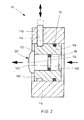
- the trailer brake valve 1 shows a longitudinal section of a trailer brake valve 1 for supplying pressure medium to a brake port B and a consumer port N.
- the trailer brake valve 1 consists essentially of a brake slide assembly 2, a flow control valve 4 for controlling the pressure medium volume flow to the brake port B of the trailer brake, a control spring assembly 6 on the maximum Trailer brake pressure is limited and arranged between the flow control valve 4 and the brake port B check valve 8, which prevents a backflow from the brake port B to the flow control valve 4.
- the pressure medium supply of the trailer brake valve 1 via a pump port P, which is connected to a pump, not shown, the Switzerland.
- the brake slide assembly 2 is to control the trailer brake pressure via a control terminal X in one direction in response to the Anlagen scholarbremstik (pilot pressure p x ) from a booster piston assembly 10 is applied, via the flow control valve 4, the pump port P is connected to the brake port B of the trailer brake and on the Brake slide assembly 2 connected to a pressure medium sink return port R to the brake port B is connected, so that the brake slide assembly 2 in response to the voltage applied to the control port X pilot pressure p x via the booster piston assembly 10 is controllable.
- the trailer brake valve 1 has a valve housing 12 with a longitudinal bore 14, in which a valve spool 16 of the flow control valve 4 is guided displaceably on the opposite the pressure fluid flow direction, a control spring 18 acts, which is supported on a screwed into the valve housing 12 screw 20.
- the valve slide 16 is penetrated by an axial bore 22 in which a diaphragm 24 is arranged. Downstream of the aperture 24, the axial bore 22 is tapered to a throttle 26, which has a relation to the aperture 24 much smaller inner diameter.
- annular grooves 28, 30, 32 are formed, wherein the annular groove 28 is connected to the load port N.
- annular groove 30 opens a pressure medium channel 34 into which a housing bore 36 extends, in which the blocking in the direction of the flow control valve 4 check valve 8 is arranged.
- a pressure medium channel 38 goes out, which opens into an annular space 40 of a parallel to the longitudinal bore 14 extending valve bore 42.
- a connecting channel 44 which opens into an annular groove 46 of the valve bore 42.
- space 48 of the valve spool 16 open at the level of the annular groove 30, a plurality of radial bores 50 a.
- the brake slide assembly 2 consists essentially of a control piston 58 in which a spool 60 is fixed, the left end portion is guided in a control portion 62 of the housing bore 56, while its right portion is guided by a sealing sleeve 64 in a radially enlarged end portion 66 of the valve bore 42 ,
- the sealing collar 64 is connected via a disc 68 to an insert screwed into the valve bore 42 70 supported.
- the spool 60 is supported via a spring plate 72 on the control spring assembly 6, which is mounted on a transitional piston 74 in an approximately cup-shaped slide 76.
- the annular wall of the control piston 58 of the brake slide assembly 2 is penetrated by a radial bore 80 which is connected via an annular groove 82 and a jacket bore 84 of the housing insert 54 in the illustrated operating position of the brake slide assembly 2 with the connecting channel 44.
- On the end wall of the control piston 58 engages a return spring 87, which biases the control piston 58 via the spool 60 against the control spring assembly 6.
- the end wall is interrupted by a pressure equalization bore 88.
- the brake slide assembly 2 is applied to control the trailer brake pressure in one direction in response to the pilot pressure p x from the booster piston assembly 10.
- the booster piston assembly has two control surfaces 100, 102 which can be acted upon by the pilot pressure p x and are effective for adjusting the brake pressure p b either together or individually. This makes it possible to adjust the gear ratio in operation to different loading conditions of the trailer and the trailer size in order to achieve an optimal braking effect.
- the booster piston assembly 10 extends according to the illustrated embodiment of the invention along A valve longitudinal axis 104 and consists essentially of a piston ring 106 and a cylinder piston 108 guided in this displaceably.
- the piston ring 106 can be fixed via a blocking device 110 in a housing 114 arranged between the valve housing 12 and a drive head 112, so that the piston ring 106 together with the cylinder piston 108 (force on brake slide assembly 2 corresponds to the pilot pressure p x times control surface 100 added with control surface 102) or in accordance with Figure 1 operated locking device 110, only the cylinder piston 108 against the brake slide assembly 2 acts (force on brake slide assembly 2 corresponds to the pilot pressure p x times control surface 102), so that a stepwise adjustable load adjustment of the trailer brake is achieved.
- the booster piston assembly 10 is disposed in the drive head 112.
- the switching between the individual translations via the locking device 110 is as a locking device 110, a slidably disposed in a radial bore 116 of the housing 114 cylindrical pin use, which is partially engageable with an outer circumferential groove 118 of the piston ring 106 into engagement.
- the locking device 110 may be mechanically, electrically, pneumatically and / or hydraulically actuated.
- the cylinder piston 108 has a radial collar 120 whose annular shoulder 122 forms a stop for the piston ring 106. This will cause the cylinder piston 108 taken with the locking device 110 open by the piston ring 106, wherein the power is transmitted to the brake slide assembly 2 via a spherical end face 124 of the radial collar 120.
- the piston ring 106 is sealed via a seal 78 relative to the housing 114 and the cylinder piston 108 via a seal 86 relative to the piston ring 106.
- the control spring assembly 6 has a supported on the transition piston 74 and acting on the spring plate 72 first control spring 126, wherein the transitional piston 74 runs after a first way on a radial shoulder 75 of the spring plate 72 and this entrains, so that a second supported on the slide 76 and on the transition piston 74 attacking control spring 128 is compressed and with the from the pilot pressure p x resulting force on the cylinder piston 108 determines the force acting on the spool 60 in Bremstik alone detox maximum force for maximum pressure limit of the trailer brake system.
- the booster piston assembly 10 has two control surfaces 100, 102, which can be acted upon to adjust the brake pressure p b either jointly or individually effective with the pilot pressure p x , it is possible as described above to adjust the gear ratio in operation to different loading conditions of the trailer and trailer sizes in order to achieve an optimal braking effect.
- the piston ring 106 can be fixed via the locking device 110, so that it acts together with the cylinder piston 108 or actuated locking device 110 according to the figures, only the cylinder piston 108 against the brake slide assembly 2. This makes it possible to adjust via the locking device 110, the brake pressure p b of the trailer brake system to different trailer sizes and loading conditions of the trailer in order to achieve optimum braking effect.
- the maximum permissible trailer brake pressure pb is reached.
- a further increase in the trailer brake pressure is prevented by the control spring assembly 6, even if the tractor brake pressure continues to increase.
- the biased to the maximum allowable trailer brake pressure control springs 126, 128 are pressed, the spool 60 briefly opens the connection from the brake port B to the return port R and thereby prevents further increase of the brake pressure p b .
- the trailer brake valve 1 according to the invention is not limited to the described two-stage booster piston assembly 10, but the booster piston assembly 10 may have a plurality of piston parts, so that more Translation ratios are feasible. Furthermore, the invention is not limited to the illustrated embodiment and arrangement of the booster piston, for example, the booster piston can also be arranged side by side.
- a hydraulic trailer brake valve 1 for applying a trailer brake with a brake pressure
- a valve housing 12 in the valve bore 42 a brake slide assembly 2 for controlling the trailer brake pressure p b is guided displaceably in one direction in response to a pilot pressure p x of a booster piston assembly 10th is acted upon, wherein the booster piston assembly 10 at least two control surfaces 100, 102 which can be acted upon by the pilot pressure (p x ) and for adjusting the brake pressure (p b ) optionally together or individually effective.
Landscapes
- Engineering & Computer Science (AREA)
- Transportation (AREA)
- Mechanical Engineering (AREA)
- Braking Systems And Boosters (AREA)
Applications Claiming Priority (1)
| Application Number | Priority Date | Filing Date | Title |
|---|---|---|---|
| DE200610050613 DE102006050613A1 (de) | 2006-10-26 | 2006-10-26 | Anhängerbremsventil mit Lastanpassung |
Publications (1)
| Publication Number | Publication Date |
|---|---|
| EP1916169A2 true EP1916169A2 (fr) | 2008-04-30 |
Family
ID=39110414
Family Applications (1)
| Application Number | Title | Priority Date | Filing Date |
|---|---|---|---|
| EP07017256A Withdrawn EP1916169A2 (fr) | 2006-10-26 | 2007-09-04 | Soupape de frein de remorque avec adaptation de charge |
Country Status (2)
| Country | Link |
|---|---|
| EP (1) | EP1916169A2 (fr) |
| DE (1) | DE102006050613A1 (fr) |
Cited By (2)
| Publication number | Priority date | Publication date | Assignee | Title |
|---|---|---|---|---|
| CN107380154A (zh) * | 2017-08-21 | 2017-11-24 | 闫明李 | 拖拉机挂车刹车控制阀 |
| WO2019154995A2 (fr) | 2018-02-09 | 2019-08-15 | Poclain Hydraulics Industrie | Procede et valve de pilotage de freinage d'un essieu de vehicule, systeme de freinage et vehicule ainsi equipe |
Families Citing this family (3)
| Publication number | Priority date | Publication date | Assignee | Title |
|---|---|---|---|---|
| DE202010014789U1 (de) * | 2010-10-27 | 2012-01-30 | Alois Pöttinger Maschinenfabrik Gmbh | Landwirtschaftliches Anbaugerät |
| DE102019114346A1 (de) * | 2019-05-28 | 2020-12-03 | Horsch Maschinen Gmbh | Bremssystem für einen landwirtschaftlich einsetzbaren Anhänger sowie landwirtschaftlicher Zugverbund, umfassend eine Zugmaschine und wenigstens einen damit gekoppelten Anhänger |
| DE102019114345A1 (de) * | 2019-05-28 | 2020-12-03 | Horsch Maschinen Gmbh | Bremssystem für eine landwirtschaftliche Arbeitsmaschine sowie landwirtschaftlicher Zugverbund, umfassend eine Zugmaschine und wenigstens eine damit gekoppelte Arbeitsmaschine |
-
2006
- 2006-10-26 DE DE200610050613 patent/DE102006050613A1/de not_active Withdrawn
-
2007
- 2007-09-04 EP EP07017256A patent/EP1916169A2/fr not_active Withdrawn
Non-Patent Citations (1)
| Title |
|---|
| None |
Cited By (5)
| Publication number | Priority date | Publication date | Assignee | Title |
|---|---|---|---|---|
| CN107380154A (zh) * | 2017-08-21 | 2017-11-24 | 闫明李 | 拖拉机挂车刹车控制阀 |
| CN107380154B (zh) * | 2017-08-21 | 2024-02-20 | 闫明李 | 拖拉机挂车刹车控制阀 |
| WO2019154995A2 (fr) | 2018-02-09 | 2019-08-15 | Poclain Hydraulics Industrie | Procede et valve de pilotage de freinage d'un essieu de vehicule, systeme de freinage et vehicule ainsi equipe |
| FR3077790A1 (fr) * | 2018-02-09 | 2019-08-16 | Poclain Hydraulics Industrie | Procede et valve de pilotage de freinage d'un essieu de vehicule, systeme de freinage et vehicule ainsi equipe |
| WO2019154995A3 (fr) * | 2018-02-09 | 2019-12-05 | Poclain Hydraulics Industrie | Procede et valve de pilotage de freinage d'un essieu de vehicule, systeme de freinage et vehicule ainsi equipe |
Also Published As
| Publication number | Publication date |
|---|---|
| DE102006050613A1 (de) | 2008-04-30 |
Similar Documents
| Publication | Publication Date | Title |
|---|---|---|
| DE102010037349B4 (de) | Parkventil für einen Nutzfahrzeug-Anhänger | |
| DE2520889A1 (de) | Zweiwegeabsperrventil, insbesondere fuer pneumatische kraftfahrzeugbremsanlagen | |
| DE112007002668B4 (de) | Bremsvorrichtung für ein Fahrzeug | |
| EP1916169A2 (fr) | Soupape de frein de remorque avec adaptation de charge | |
| EP1794045B1 (fr) | Cylindre de frein pour freins de vehicules | |
| DE19514733B4 (de) | Bremsventil | |
| EP3114365B1 (fr) | Amplificateur de force d'embrayage comprenant des moyens d'étanchéité dynamiques spécifiques disposés dans la zone de la tige de piston | |
| DE2814414A1 (de) | Bremskraftregler fuer zweikreisbremsanlagen | |
| DE19932670C2 (de) | Hauptzylinderanordnung | |
| DE69806493T2 (de) | Hauptzylinder mit ventile mit reduziertem betätigungstotgang | |
| DE3627902A1 (de) | Hydraulischer kraftverstaerker | |
| EP2164732B1 (fr) | Systeme de freinage hydraulique de vehicule et procede de fonctionnement de ce systeme | |
| DE2402291C3 (de) | Bremskraftregler für eine Mehrkreisbremsanlage | |
| DE3820539C2 (fr) | ||
| DE69112971T2 (de) | Hydraulisches Bremsdruckregelsystem. | |
| EP1137564B1 (fr) | Soupape de frein de remorque | |
| DE3011633A1 (de) | Druckminderer fuer hydraulische bremskraftanlagen | |
| DE10236686A1 (de) | Bremszange | |
| DE69109441T2 (de) | Hydraulisches Bremsdruckregelsystem. | |
| DE19728278A1 (de) | Fahrzeug-Bremskraftverstärker | |
| DE3439192C2 (fr) | ||
| DE1555121B2 (de) | Blockiergeschutzte Fahrzeugbremsanlage | |
| DE102006033534A1 (de) | Pneumatischer Bremskraftverstärker | |
| EP1791737B1 (fr) | Systeme de freinage pour vehicule | |
| DE10325875A1 (de) | Bremssystem |
Legal Events
| Date | Code | Title | Description |
|---|---|---|---|
| PUAI | Public reference made under article 153(3) epc to a published international application that has entered the european phase |
Free format text: ORIGINAL CODE: 0009012 |
|
| AK | Designated contracting states |
Kind code of ref document: A2 Designated state(s): AT BE BG CH CY CZ DE DK EE ES FI FR GB GR HU IE IS IT LI LT LU LV MC MT NL PL PT RO SE SI SK TR |
|
| AX | Request for extension of the european patent |
Extension state: AL BA HR MK RS |
|
| STAA | Information on the status of an ep patent application or granted ep patent |
Free format text: STATUS: THE APPLICATION IS DEEMED TO BE WITHDRAWN |
|
| 18D | Application deemed to be withdrawn |
Effective date: 20140401 |