EP1916209A2 - Bobineuse à deux rouleaux de support destinée à l'embobinage d'une bande de matériau - Google Patents
Bobineuse à deux rouleaux de support destinée à l'embobinage d'une bande de matériau Download PDFInfo
- Publication number
- EP1916209A2 EP1916209A2 EP07118665A EP07118665A EP1916209A2 EP 1916209 A2 EP1916209 A2 EP 1916209A2 EP 07118665 A EP07118665 A EP 07118665A EP 07118665 A EP07118665 A EP 07118665A EP 1916209 A2 EP1916209 A2 EP 1916209A2
- Authority
- EP
- European Patent Office
- Prior art keywords
- winding
- winding machine
- drive unit
- double
- traverse
- Prior art date
- Legal status (The legal status is an assumption and is not a legal conclusion. Google has not performed a legal analysis and makes no representation as to the accuracy of the status listed.)
- Withdrawn
Links
Images

Classifications
-
- B—PERFORMING OPERATIONS; TRANSPORTING
- B65—CONVEYING; PACKING; STORING; HANDLING THIN OR FILAMENTARY MATERIAL
- B65H—HANDLING THIN OR FILAMENTARY MATERIAL, e.g. SHEETS, WEBS, CABLES
- B65H18/00—Winding webs
- B65H18/08—Web-winding mechanisms
- B65H18/14—Mechanisms in which power is applied to web roll, e.g. to effect continuous advancement of web
- B65H18/20—Mechanisms in which power is applied to web roll, e.g. to effect continuous advancement of web the web roll being supported on two parallel rollers at least one of which is driven
-
- B—PERFORMING OPERATIONS; TRANSPORTING
- B65—CONVEYING; PACKING; STORING; HANDLING THIN OR FILAMENTARY MATERIAL
- B65H—HANDLING THIN OR FILAMENTARY MATERIAL, e.g. SHEETS, WEBS, CABLES
- B65H18/00—Winding webs
- B65H18/08—Web-winding mechanisms
- B65H18/26—Mechanisms for controlling contact pressure on winding-web package, e.g. for regulating the quantity of air between web layers
-
- B—PERFORMING OPERATIONS; TRANSPORTING
- B65—CONVEYING; PACKING; STORING; HANDLING THIN OR FILAMENTARY MATERIAL
- B65H—HANDLING THIN OR FILAMENTARY MATERIAL, e.g. SHEETS, WEBS, CABLES
- B65H2301/00—Handling processes for sheets or webs
- B65H2301/40—Type of handling process
- B65H2301/41—Winding, unwinding
- B65H2301/414—Winding
- B65H2301/4148—Winding slitting
-
- B—PERFORMING OPERATIONS; TRANSPORTING
- B65—CONVEYING; PACKING; STORING; HANDLING THIN OR FILAMENTARY MATERIAL
- B65H—HANDLING THIN OR FILAMENTARY MATERIAL, e.g. SHEETS, WEBS, CABLES
- B65H2403/00—Power transmission; Driving means
- B65H2403/50—Driving mechanisms
- B65H2403/52—Translation screw-thread mechanisms
-
- B—PERFORMING OPERATIONS; TRANSPORTING
- B65—CONVEYING; PACKING; STORING; HANDLING THIN OR FILAMENTARY MATERIAL
- B65H—HANDLING THIN OR FILAMENTARY MATERIAL, e.g. SHEETS, WEBS, CABLES
- B65H2404/00—Parts for transporting or guiding the handled material
- B65H2404/40—Shafts, cylinders, drums, spindles
- B65H2404/43—Rider roll construction
Definitions
- the invention relates to a double carrier roll winding machine for winding a divided by at least one longitudinal section material web, in particular a paper or board web, at least one winding tube to at least one winding roll, wherein the at least one winding roll is at least during the winding process in a winding bed formed by two support rollers and wherein a force acting on the at least one winding roller pressure roller system is provided, which has a horizontally extending and at least vertically displaceable cross member on which at least one pressure roller is arranged with an axis parallel to the cross member.
- Material webs must be wound up into shipping or finishing rolls before they can be shipped.
- reel cores usually winding cores are used, which are preferably made of cardboard.
- the finished rolls are produced by so-called mother or spool rolls, which are produced at the exit of a paper or board machine or after the calendering of the web, unwound, cut in the longitudinal direction and then wound on each winding cores.
- mother or spool rolls which are produced at the exit of a paper or board machine or after the calendering of the web, unwound, cut in the longitudinal direction and then wound on each winding cores.
- These cores lie in a winding bed formed by two support rollers of a double carrier roll winding machine.
- a pressure roller system which consists of a continuous pressure roller or of individual pressure roller segments and is arranged on a horizontal and at least vertically movable traverse.
- the pressure roller system serves to press at the beginning of the winding from above on the bobbins, so as to increase the line load at the contact lines between the bobbins and the support rollers.
- the line load decisively influences the winding hardness and thus the winding quality of the winding rolls.
- the line load from the weight of the winding rollers is not enough. Therefore, an additional contact force is applied by means of the pressure roller system, which is correspondingly reduced with increasing roll weight during winding.
- a double winder-winding machine with such a pressure roller system is for example from the document DE 102 51 592 A1 known.
- the at least vertical displacement of the traverse of the printing roller system takes place in the known double-carrier roller winding machines by means of pneumatic or hydraulic linear drives, for example in the design of double-acting cylinders.
- the force acting on the web support force of the printing roller system is controlled by means of an additional pressure or force control.
- the known pressure roller system has disadvantageously the so-called stick-slip effect, so that after a set change not always a pinpoint positioning of the traverse and thus the pressure rollers can be ensured.
- the stick-slip effect refers to the jerking of mutually moving solids.
- damped-coupled surface parts exert a fast sequence of movements of adhesion, distortion, separation and slipping. Depending on the tribosystem, this leads to the excitation of vibrations that are emitted as noise by a resonant surface. The effect usually disappears as soon as the friction partners are separated by an intermediate or lubricant.
- the known pressure roller systems often have a control behavior that is not tolerable in the production process.
- the invention is therefore the object of developing a reel winding device of the type mentioned in such a way that the mentioned disadvantages of the prior art significantly reduced, preferably even completely avoided.
- the maximum traversing speed of the traverse should also be increased.
- At least one preferably controlled / regulated electromechanical drive unit for at least vertical displacement of at least one pressure roller having traverse is provided.
- the invention is characterized by the successful realization of three goals, that is, three subtasks by means of a single measure.
- a no stick-slip effect having drive unit so a pinpoint positioning of the traverse and thus the pressure rollers can be ensured continuously after each set change.
- no use is made of any other foreign medium, in particular hydraulic oil, for the operation of the displacement system.
- an electromechanical drive unit does not make use of a potentially leaking medium, the functioning of the displacement system can be guaranteed at any time of operation.
- the displacement device according to the invention has no hysteresis. This occurring in the prior art hysteresis may result in that the crossbar can not be accurately positioned. This in turn means that the pressure rollers and the winding rollers tend to be slightly distorted. If this type of tension occurs, it inevitably triggers vibrations due to the wobbling motion of the winding rollers, which can cause winding errors. This is avoided due to the use of the displacement device according to the invention.
- the contact pressure on the width of the double-winder winding machine can be applied sufficiently and preferably evenly on the at least one winding roll, the at least one electromechanical drive unit preferably acts mirror-image, especially on both sides of the at least one pressure roller having traverse.
- the electromechanical drive unit preferably comprises at least one preferably controllable electric motor and at least one spindle drive.
- the precisely operating spindle drive preferably uses at least one spindle rod acted upon by the electric motor arranged on a stationary component, in particular a main body of the double-carrier roller winding machine, and at least one spindle nut mounted directly or indirectly on the traverse. This displacement system is particularly suitable for the transmission of large forces.
- the electromechanical drive unit preferably comprises at least one preferably controllable / controllable one Linear drive unit, in particular a preferably controllable and guided by at least one linear guide linear motor.
- the linear motor are arranged directly on the traverse and the at least one linear guide on a stationary component, in particular a main body of the double-carrier winding machine.
- a preferably linear measuring system arranged on the electromechanical drive unit is provided.
- This measuring system can interact with another control system and the electric motor drive unit can also be used for active vibration damping.
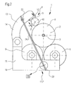
- a double carrier roll winding machine 1 for winding up a material web 2 divided by a longitudinal section onto a winding tube 3 to form a winding roll 4 is shown in frontal view.
- the winding roller 4 can be guided during operation in each case a frontally arranged and acting and not explicitly shown guide head in the vertical direction. It is also possible to simultaneously wind a plurality of winding rolls 4 arranged along a line in the double-takeup roll winding machine 1.
- the material web 2 can be, for example, a paper web which is wound up into a paper web roll.
- the invention is also applicable to other material webs, which also have to be wound into bobbins and handled in a similar manner, such as webs of cardboard, plastic or metal foil, respectively.
- a force acting on the winding roller 4 pressure roller system 8 is provided, which has a horizontally extending and at least vertically displaceable traverse 9, on which at least one pressure roller 10 is arranged with an axis 11 parallel to the traverse.
- the attachment of the pressure roller 10 can be done for example via storage units 12.
- the traverse 9 is preferably wholly or partly made of steel, aluminum or from a reinforced by a glass or carbon fiber composite highly load-bearing plastic and has, including arranged on her aggregates in a favorable manner a weight of less than 600 kg / m, in particular less than 550 kg / m, based on their length, on. In addition, it may have the form of a double-T-carrier in unillustrated embodiment.
- the cross member 9 is pivotally mounted by means of a two pivot lever 14 having pivot lever pair 13 on a stationary component 15, in particular a main body 16 of the double carrier rollers winding machine 1.
- the traverse 9 could be additionally or solely linearly displaceable.
- the two support rollers 5, 6 are mounted on the stationary component 15 in a known manner.
- a preferably controlled / regulated electromechanical drive unit 17 for at least vertical displacement V (double arrow) of the traverse 9 having at least one pressure roller 10 is provided on the respective double carrier roller winding machine 1 illustrated in FIGS.
- the electromechanical drive unit 17 acts indirectly via the pivot lever 14 of the pivot lever pair 13 on the traverse 9.
- the electromechanical drive unit 17 also directly, so act directly on the traverse 9.
- an electromechanical drive unit 17 in each case acts on the end side, that is to say in total on both sides on the traverse 9 having the at least one pressure roller 10.
- the electromechanical drive unit 17 comprises a preferably controllable electric motor 18 and at least one spindle gear 19 which engages a spindle rod 20 which is acted upon by the electric motor 18 arranged on the stationary component 15, in particular the base body 16 of the double-carrier roller winding machine 1 and an indirectly attached to the cross member 9 spindle nut 21 has.
- Both the electric motor 18 and the spindle nut 21 mounted on the pivoting lever 14, for example, are rotatably arranged due to changing geometries during operation.
- the electromechanical drive unit 17 in the embodiment of FIG. 2 comprises a preferably controllable linear drive unit 22, in particular a preferably controllable / controllable linear motor 23 guided by at least one linear guide 24.
- the linear motor 23 is arranged indirectly on the traverse 9 and the linear guide 24 on the stationary component 15, in particular the base body 16 of the double-carrier roller winding machine 1.
- the linear motor 23 is attached to the pivot lever 14, for example.
- the components 23, 24 in reverse Be arranged manner. Both the linear guide 24 and the linear motor 23 are rotatably arranged due to changing geometries during operation.
- a preferably linear measuring system 25 arranged on the electromechanical drive unit 17 and merely indicated is provided. Since such a measuring system 25 together with an optional control system is known to the person skilled in the art, a detailed description and description will be omitted here.
- the respective electromechanical drive unit 17 shown in FIGS. 1 and 2 can also be configured otherwise.
- it can comprise at least one preferably controllable electric motor and at least one belt transmission, wherein the belt transmission preferably has a flat belt, a V-belt, a toothed belt, a wedge flat / toothed belt, a round belt or the like.
- the invention provides a double winder winding machine of the type mentioned in such a way that the mentioned disadvantages of the prior art significantly reduced, preferably even completely avoided.
- the maximum traversing speed of the traverse is increased.
Landscapes
- Winding Of Webs (AREA)
- Replacement Of Web Rolls (AREA)
Applications Claiming Priority (1)
| Application Number | Priority Date | Filing Date | Title |
|---|---|---|---|
| DE200620016209 DE202006016209U1 (de) | 2006-10-24 | 2006-10-24 | Doppeltragwalzen-Wickelmaschine zum Aufwickeln einer Materialbahn |
Publications (2)
| Publication Number | Publication Date |
|---|---|
| EP1916209A2 true EP1916209A2 (fr) | 2008-04-30 |
| EP1916209A3 EP1916209A3 (fr) | 2009-07-08 |
Family
ID=37576280
Family Applications (1)
| Application Number | Title | Priority Date | Filing Date |
|---|---|---|---|
| EP07118665A Withdrawn EP1916209A3 (fr) | 2006-10-24 | 2007-10-17 | Bobineuse à deux rouleaux de support destinée à l'embobinage d'une bande de matériau |
Country Status (2)
| Country | Link |
|---|---|
| EP (1) | EP1916209A3 (fr) |
| DE (1) | DE202006016209U1 (fr) |
Cited By (2)
| Publication number | Priority date | Publication date | Assignee | Title |
|---|---|---|---|---|
| CN108116925A (zh) * | 2017-12-19 | 2018-06-05 | 芜湖华烨新材料有限公司 | 一种防褶皱按压固定验布机 |
| CN114700400A (zh) * | 2022-05-07 | 2022-07-05 | 江苏春秋重型机械有限公司 | 一种具有上横梁辅助压制的卷板机及其卷制方法 |
Families Citing this family (2)
| Publication number | Priority date | Publication date | Assignee | Title |
|---|---|---|---|---|
| DE102007002218A1 (de) * | 2007-01-10 | 2008-07-17 | Sms Demag Ag | Wickelvorrichtung zum Wickeln von Bändern |
| RU2475440C1 (ru) * | 2011-08-12 | 2013-02-20 | Федеральное государственное бюджетное образовательное учреждение высшего профессионального образования Владивостокский государственный университет экономики и сервиса (ВГУЭС) | Устройство для намотки в рулон длинномерных сдублированных в пакет легкодеформируемых материалов |
Family Cites Families (4)
| Publication number | Priority date | Publication date | Assignee | Title |
|---|---|---|---|---|
| US3206134A (en) * | 1963-12-05 | 1965-09-14 | Diamond Int Corp | Web winding apparatus |
| EP1375401B1 (fr) * | 2002-06-25 | 2007-01-03 | A. CELLI NONWOVENS S.p.A. | Ré-enrouleuse avec des cylindres auxiliaires et méthode d'enroulement associée |
| DE10251592B4 (de) * | 2002-11-06 | 2007-11-08 | Voith Patent Gmbh | Tragwalzen-Wickelmaschine |
| DE102004051253A1 (de) * | 2004-10-21 | 2006-04-27 | Voith Paper Patent Gmbh | Wickelmaschine |
-
2006
- 2006-10-24 DE DE200620016209 patent/DE202006016209U1/de not_active Expired - Lifetime
-
2007
- 2007-10-17 EP EP07118665A patent/EP1916209A3/fr not_active Withdrawn
Cited By (2)
| Publication number | Priority date | Publication date | Assignee | Title |
|---|---|---|---|---|
| CN108116925A (zh) * | 2017-12-19 | 2018-06-05 | 芜湖华烨新材料有限公司 | 一种防褶皱按压固定验布机 |
| CN114700400A (zh) * | 2022-05-07 | 2022-07-05 | 江苏春秋重型机械有限公司 | 一种具有上横梁辅助压制的卷板机及其卷制方法 |
Also Published As
| Publication number | Publication date |
|---|---|
| DE202006016209U1 (de) | 2006-12-21 |
| EP1916209A3 (fr) | 2009-07-08 |
Similar Documents
| Publication | Publication Date | Title |
|---|---|---|
| EP0614838A1 (fr) | Rouleau de pression interchangeable | |
| DE2812958C2 (fr) | ||
| EP1000893B1 (fr) | Enrouleuse pour enrouler une bande de matériau | |
| EP1916209A2 (fr) | Bobineuse à deux rouleaux de support destinée à l'embobinage d'une bande de matériau | |
| EP2881348B1 (fr) | Dispositif pour l'enroulage une bande de matériau et pour le positionnement de bobines. | |
| EP2253567B1 (fr) | Dispositif d'enroulement continu d'une bande de matière fibreuse | |
| EP1591390B1 (fr) | Bobineuse pour le bobinage continu d'une bande de matériau | |
| DE102011112001A1 (de) | Doppeltragwalzenroller | |
| EP1818296B1 (fr) | Dispositif d'enroulement de rouleaux | |
| EP1086916A2 (fr) | Unité de palier pour rouleaux tendeurs de bandes de matériau | |
| DE102011116308A1 (de) | Doppeltragwalzenroller | |
| EP1591391B1 (fr) | Bobineuse pour le bobinage continu d'une bande de matériau | |
| DE19748995A1 (de) | Verfahren und Wickelmaschine zum kontinuierlichen Aufwickeln einer Materialbahn | |
| DE102008043310A1 (de) | Breitstreckeinrichtung | |
| EP0507045A1 (fr) | Machine pour enrouler une bande | |
| AT509265B1 (de) | Wickelpartie für einen rollenschneider einer faserbahn und verfahren zum modernisieren einer wickelpartie für einen rollenschneider einer faserbahn | |
| DE102005000117A1 (de) | Rollenwickelvorrichtung | |
| DE102008053467A1 (de) | Mit einem Druckwalzenbalken und einer Druckwalze versehener Aufroller vom Tragwalzentyp und Verfahren | |
| EP2019060B1 (fr) | Dispositif d'enroulement et procédé d'enroulement de bandes de matière fibreuse dans un dispositif d'enroulement | |
| DE8708849U1 (de) | Doppeltragwalzen-Wickelmaschine | |
| DE202008009998U1 (de) | Wickelmaschine zum kontinuierlichen Aufwickeln einer Materialbahn | |
| DE102013209559A1 (de) | Vorrichtung zum Aufrollen einer Materialbahn zu einer Rolle und Verfahren zur Verwendung dieser Vorrichtung | |
| DE10203149B4 (de) | Vorrichtung zum Andrücken eines beweglichen Maschinenteils gegen ein anderes | |
| AT506333B1 (de) | Verfahren und vorrichtung in einem rollapparat einer papierbahn | |
| DE3100522A1 (de) | Walzenpresse |
Legal Events
| Date | Code | Title | Description |
|---|---|---|---|
| PUAI | Public reference made under article 153(3) epc to a published international application that has entered the european phase |
Free format text: ORIGINAL CODE: 0009012 |
|
| AK | Designated contracting states |
Kind code of ref document: A2 Designated state(s): AT BE BG CH CY CZ DE DK EE ES FI FR GB GR HU IE IS IT LI LT LU LV MC MT NL PL PT RO SE SI SK TR |
|
| AX | Request for extension of the european patent |
Extension state: AL BA HR MK RS |
|
| PUAL | Search report despatched |
Free format text: ORIGINAL CODE: 0009013 |
|
| AK | Designated contracting states |
Kind code of ref document: A3 Designated state(s): AT BE BG CH CY CZ DE DK EE ES FI FR GB GR HU IE IS IT LI LT LU LV MC MT NL PL PT RO SE SI SK TR |
|
| AX | Request for extension of the european patent |
Extension state: AL BA HR MK RS |
|
| RIC1 | Information provided on ipc code assigned before grant |
Ipc: B65H 18/26 20060101ALI20090529BHEP Ipc: B65H 18/20 20060101AFI20080205BHEP |
|
| 17P | Request for examination filed |
Effective date: 20100108 |
|
| AKX | Designation fees paid |
Designated state(s): AT DE FI IT SE |
|
| 17Q | First examination report despatched |
Effective date: 20100310 |
|
| STAA | Information on the status of an ep patent application or granted ep patent |
Free format text: STATUS: THE APPLICATION HAS BEEN WITHDRAWN |
|
| 18W | Application withdrawn |
Effective date: 20100720 |
|
| P01 | Opt-out of the competence of the unified patent court (upc) registered |
Effective date: 20230522 |