EP1916309A2 - Traitement de surface de matériel composite en carbone pour améliorer les propriétés électrochimiques - Google Patents
Traitement de surface de matériel composite en carbone pour améliorer les propriétés électrochimiques Download PDFInfo
- Publication number
- EP1916309A2 EP1916309A2 EP07254257A EP07254257A EP1916309A2 EP 1916309 A2 EP1916309 A2 EP 1916309A2 EP 07254257 A EP07254257 A EP 07254257A EP 07254257 A EP07254257 A EP 07254257A EP 1916309 A2 EP1916309 A2 EP 1916309A2
- Authority
- EP
- European Patent Office
- Prior art keywords
- substrate
- layer
- electrode
- carbon
- corona discharge
- Prior art date
- Legal status (The legal status is an assumption and is not a legal conclusion. Google has not performed a legal analysis and makes no representation as to the accuracy of the status listed.)
- Withdrawn
Links
- OKTJSMMVPCPJKN-UHFFFAOYSA-N Carbon Chemical compound [C] OKTJSMMVPCPJKN-UHFFFAOYSA-N 0.000 title claims description 89
- 229910052799 carbon Inorganic materials 0.000 title claims description 70
- 239000002131 composite material Substances 0.000 title claims description 19
- 238000004381 surface treatment Methods 0.000 title description 16
- 238000003851 corona treatment Methods 0.000 claims abstract description 61
- 238000000034 method Methods 0.000 claims abstract description 56
- 238000000151 deposition Methods 0.000 claims abstract description 18
- 239000000758 substrate Substances 0.000 claims description 91
- 238000012360 testing method Methods 0.000 claims description 62
- 238000007639 printing Methods 0.000 claims description 44
- 108090000790 Enzymes Proteins 0.000 claims description 39
- 102000004190 Enzymes Human genes 0.000 claims description 39
- 238000009413 insulation Methods 0.000 claims description 31
- 239000000463 material Substances 0.000 claims description 31
- 229920000642 polymer Polymers 0.000 claims description 26
- WQZGKKKJIJFFOK-GASJEMHNSA-N Glucose Natural products OC[C@H]1OC(O)[C@H](O)[C@@H](O)[C@@H]1O WQZGKKKJIJFFOK-GASJEMHNSA-N 0.000 claims description 21
- 239000008103 glucose Substances 0.000 claims description 21
- 238000004519 manufacturing process Methods 0.000 claims description 16
- 239000000853 adhesive Substances 0.000 claims description 11
- 230000001070 adhesive effect Effects 0.000 claims description 11
- 239000008280 blood Substances 0.000 claims description 11
- 210000004369 blood Anatomy 0.000 claims description 11
- 238000005259 measurement Methods 0.000 claims description 8
- 210000001124 body fluid Anatomy 0.000 claims description 5
- 239000010839 body fluid Substances 0.000 claims description 5
- 238000001514 detection method Methods 0.000 claims description 5
- 239000002952 polymeric resin Substances 0.000 claims description 5
- 229920003002 synthetic resin Polymers 0.000 claims description 5
- 239000007772 electrode material Substances 0.000 claims description 2
- VNWKTOKETHGBQD-UHFFFAOYSA-N methane Chemical compound C VNWKTOKETHGBQD-UHFFFAOYSA-N 0.000 abstract description 23
- 238000007650 screen-printing Methods 0.000 abstract description 8
- 239000010410 layer Substances 0.000 description 65
- 208000028659 discharge Diseases 0.000 description 45
- 239000000976 ink Substances 0.000 description 45
- 229940088598 enzyme Drugs 0.000 description 35
- 229910002804 graphite Inorganic materials 0.000 description 18
- 239000010439 graphite Substances 0.000 description 18
- 238000001035 drying Methods 0.000 description 16
- 239000002245 particle Substances 0.000 description 16
- 239000002904 solvent Substances 0.000 description 14
- 239000006229 carbon black Substances 0.000 description 11
- 239000012790 adhesive layer Substances 0.000 description 10
- 239000003570 air Substances 0.000 description 10
- 230000008021 deposition Effects 0.000 description 10
- 239000000203 mixture Substances 0.000 description 10
- 230000010287 polarization Effects 0.000 description 9
- 238000010586 diagram Methods 0.000 description 8
- 239000007788 liquid Substances 0.000 description 7
- 239000010409 thin film Substances 0.000 description 7
- 238000000840 electrochemical analysis Methods 0.000 description 6
- 238000012545 processing Methods 0.000 description 6
- 150000001875 compounds Chemical class 0.000 description 4
- 230000005684 electric field Effects 0.000 description 4
- 239000010408 film Substances 0.000 description 4
- 239000002861 polymer material Substances 0.000 description 4
- 230000000694 effects Effects 0.000 description 3
- -1 imidazole-substituted osmium Chemical class 0.000 description 3
- 238000012544 monitoring process Methods 0.000 description 3
- 230000003647 oxidation Effects 0.000 description 3
- 238000007254 oxidation reaction Methods 0.000 description 3
- 239000004033 plastic Substances 0.000 description 3
- 229920003023 plastic Polymers 0.000 description 3
- IJGRMHOSHXDMSA-UHFFFAOYSA-N Atomic nitrogen Chemical compound N#N IJGRMHOSHXDMSA-UHFFFAOYSA-N 0.000 description 2
- CBENFWSGALASAD-UHFFFAOYSA-N Ozone Chemical compound [O-][O+]=O CBENFWSGALASAD-UHFFFAOYSA-N 0.000 description 2
- 239000012491 analyte Substances 0.000 description 2
- 230000009286 beneficial effect Effects 0.000 description 2
- 230000015572 biosynthetic process Effects 0.000 description 2
- 239000000919 ceramic Substances 0.000 description 2
- 230000003247 decreasing effect Effects 0.000 description 2
- 206010012601 diabetes mellitus Diseases 0.000 description 2
- 230000002708 enhancing effect Effects 0.000 description 2
- 238000000605 extraction Methods 0.000 description 2
- 239000012530 fluid Substances 0.000 description 2
- 238000009472 formulation Methods 0.000 description 2
- 125000000524 functional group Chemical group 0.000 description 2
- PCHJSUWPFVWCPO-UHFFFAOYSA-N gold Chemical compound [Au] PCHJSUWPFVWCPO-UHFFFAOYSA-N 0.000 description 2
- 239000010931 gold Substances 0.000 description 2
- 229910052737 gold Inorganic materials 0.000 description 2
- 238000010438 heat treatment Methods 0.000 description 2
- 230000002401 inhibitory effect Effects 0.000 description 2
- 238000012986 modification Methods 0.000 description 2
- 230000004048 modification Effects 0.000 description 2
- 230000001590 oxidative effect Effects 0.000 description 2
- 229920000728 polyester Polymers 0.000 description 2
- 238000012546 transfer Methods 0.000 description 2
- SQHWUYVHKRVCMD-UHFFFAOYSA-N 2-n,2-n-dimethyl-10-phenylphenazin-10-ium-2,8-diamine;chloride Chemical class [Cl-].C12=CC(N(C)C)=CC=C2N=C2C=CC(N)=CC2=[N+]1C1=CC=CC=C1 SQHWUYVHKRVCMD-UHFFFAOYSA-N 0.000 description 1
- 241000157855 Cinchona Species 0.000 description 1
- 235000001258 Cinchona calisaya Nutrition 0.000 description 1
- MYMOFIZGZYHOMD-UHFFFAOYSA-N Dioxygen Chemical compound O=O MYMOFIZGZYHOMD-UHFFFAOYSA-N 0.000 description 1
- 108010015776 Glucose oxidase Proteins 0.000 description 1
- 239000004366 Glucose oxidase Substances 0.000 description 1
- 241000180177 Listrocephalos corona Species 0.000 description 1
- 239000004677 Nylon Substances 0.000 description 1
- 239000004698 Polyethylene Substances 0.000 description 1
- 239000004642 Polyimide Substances 0.000 description 1
- 239000004743 Polypropylene Substances 0.000 description 1
- 239000004820 Pressure-sensitive adhesive Substances 0.000 description 1
- KJTLSVCANCCWHF-UHFFFAOYSA-N Ruthenium Chemical compound [Ru] KJTLSVCANCCWHF-UHFFFAOYSA-N 0.000 description 1
- NIXOWILDQLNWCW-UHFFFAOYSA-N acrylic acid group Chemical group C(C=C)(=O)O NIXOWILDQLNWCW-UHFFFAOYSA-N 0.000 description 1
- 229920006243 acrylic copolymer Polymers 0.000 description 1
- 239000012080 ambient air Substances 0.000 description 1
- 230000000712 assembly Effects 0.000 description 1
- 238000000429 assembly Methods 0.000 description 1
- 239000012298 atmosphere Substances 0.000 description 1
- QVGXLLKOCUKJST-UHFFFAOYSA-N atomic oxygen Chemical compound [O] QVGXLLKOCUKJST-UHFFFAOYSA-N 0.000 description 1
- 239000003153 chemical reaction reagent Substances 0.000 description 1
- 239000011248 coating agent Substances 0.000 description 1
- 238000000576 coating method Methods 0.000 description 1
- 239000000356 contaminant Substances 0.000 description 1
- 238000010924 continuous production Methods 0.000 description 1
- 238000013461 design Methods 0.000 description 1
- 238000003487 electrochemical reaction Methods 0.000 description 1
- 230000005518 electrochemistry Effects 0.000 description 1
- 230000003203 everyday effect Effects 0.000 description 1
- 230000001747 exhibiting effect Effects 0.000 description 1
- 210000003722 extracellular fluid Anatomy 0.000 description 1
- YAGKRVSRTSUGEY-UHFFFAOYSA-N ferricyanide Chemical compound [Fe+3].N#[C-].N#[C-].N#[C-].N#[C-].N#[C-].N#[C-] YAGKRVSRTSUGEY-UHFFFAOYSA-N 0.000 description 1
- KTWOOEGAPBSYNW-UHFFFAOYSA-N ferrocene Chemical compound [Fe+2].C=1C=C[CH-]C=1.C=1C=C[CH-]C=1 KTWOOEGAPBSYNW-UHFFFAOYSA-N 0.000 description 1
- 239000003574 free electron Substances 0.000 description 1
- 239000007789 gas Substances 0.000 description 1
- 229940116332 glucose oxidase Drugs 0.000 description 1
- 235000019420 glucose oxidase Nutrition 0.000 description 1
- 230000005660 hydrophilic surface Effects 0.000 description 1
- 238000009434 installation Methods 0.000 description 1
- 239000011810 insulating material Substances 0.000 description 1
- 239000012212 insulator Substances 0.000 description 1
- 230000002427 irreversible effect Effects 0.000 description 1
- 238000002955 isolation Methods 0.000 description 1
- 229910052751 metal Inorganic materials 0.000 description 1
- 239000002184 metal Substances 0.000 description 1
- 150000002739 metals Chemical class 0.000 description 1
- 229910052757 nitrogen Inorganic materials 0.000 description 1
- 229920001778 nylon Polymers 0.000 description 1
- 238000005457 optimization Methods 0.000 description 1
- 239000003960 organic solvent Substances 0.000 description 1
- 239000001301 oxygen Substances 0.000 description 1
- 229910052760 oxygen Inorganic materials 0.000 description 1
- 238000004806 packaging method and process Methods 0.000 description 1
- 229920000515 polycarbonate Polymers 0.000 description 1
- 239000004417 polycarbonate Substances 0.000 description 1
- 229920006267 polyester film Polymers 0.000 description 1
- 229920000573 polyethylene Polymers 0.000 description 1
- 229920005644 polyethylene terephthalate glycol copolymer Polymers 0.000 description 1
- 229920001721 polyimide Polymers 0.000 description 1
- 229920001155 polypropylene Polymers 0.000 description 1
- 229920000915 polyvinyl chloride Polymers 0.000 description 1
- 239000004800 polyvinyl chloride Substances 0.000 description 1
- 125000003410 quininyl group Chemical group 0.000 description 1
- 230000002829 reductive effect Effects 0.000 description 1
- 229920005989 resin Polymers 0.000 description 1
- 239000011347 resin Substances 0.000 description 1
- 230000027756 respiratory electron transport chain Effects 0.000 description 1
- 229910052707 ruthenium Inorganic materials 0.000 description 1
- 125000006850 spacer group Chemical group 0.000 description 1
- 239000000126 substance Substances 0.000 description 1
- 238000006467 substitution reaction Methods 0.000 description 1
- 239000002344 surface layer Substances 0.000 description 1
- 239000004094 surface-active agent Substances 0.000 description 1
- 230000002459 sustained effect Effects 0.000 description 1
- XLYOFNOQVPJJNP-UHFFFAOYSA-N water Substances O XLYOFNOQVPJJNP-UHFFFAOYSA-N 0.000 description 1
Images





Classifications
-
- G—PHYSICS
- G01—MEASURING; TESTING
- G01N—INVESTIGATING OR ANALYSING MATERIALS BY DETERMINING THEIR CHEMICAL OR PHYSICAL PROPERTIES
- G01N27/00—Investigating or analysing materials by the use of electric, electrochemical, or magnetic means
- G01N27/26—Investigating or analysing materials by the use of electric, electrochemical, or magnetic means by investigating electrochemical variables; by using electrolysis or electrophoresis
- G01N27/28—Electrolytic cell components
- G01N27/30—Electrodes, e.g. test electrodes; Half-cells
- G01N27/327—Biochemical electrodes, e.g. electrical or mechanical details for in vitro measurements
- G01N27/3271—Amperometric enzyme electrodes for analytes in body fluids, e.g. glucose in blood
- G01N27/3272—Test elements therefor, i.e. disposable laminated substrates with electrodes, reagent and channels
Definitions
- the present invention relates in general, to disposable test strips for use in the electrochemical determination of analytes, such as glucose, in body fluids such as blood or interstitial fluid, and more particularly to a method of manufacturing such test strips to improve electrochemical properties.
- analytes such as glucose
- body fluids such as blood or interstitial fluid
- Glucose monitoring is a fact of everyday life for people with diabetes, and the accuracy of such monitoring can literally mean the difference between life and death. Frequent testing of blood sugar levels is required for a person with diabetes to live a normal lifestyle and a number of glucose meters are commercially available to accommodate this need. Many glucose-monitoring meters detect glucose in a blood sample electrochemically, by detecting the oxidation of blood glucose using an enzyme such as glucose oxidase provided as part of a disposable, single-use electrode system. Alternative methods of glucose measurement are available such as, for example, photometric testing.
- Test strips for use in electrochemical glucose meters typically comprise a substrate material, working and reference electrodes formed on the surface of the substrate, and a means for making connection between the electrodes and the meter.
- the working electrode is typically coated with an enzyme capable of oxidizing glucose and a mediator compound.
- the mediator compound transfers electrons from the enzyme to the electrode, resulting in a measurable current when glucose is present.
- Representative mediator compounds include ferricyanide, ruthenium, metallocene compounds such as ferrocene, quinines, phenazinium salts and imidazole-substituted osmium compounds.
- Working electrodes of this type have been formulated in a number of ways.
- the required components may be formulated into a paste or ink and applied to the substrate using a screen-printing technique in order to obtain thin layers suitable for disposable test strips.
- the carbon ink used as the base for electrochemical test sensors such as the OneTouch® Ultra brand from Lifescan, Inc., Milpitas, California, USA for example, is typically composed of a mixture of graphite, carbon black and a polymer to bind them together.
- the graphite, carbon black and polymer may be dispersed in a solvent to keep the ink fluid and prevent it from separating and/or drying out.
- the solvent is removed by heating the mixture to temperatures in the range 120 to 160 degrees C. Removal of the solvent transforms the liquid ink into a paste that will reliably adhere to the substrate.
- the actual electrochemistry takes place at the surface of the carbon black and graphite particles.
- this process brings together the carbon black and graphite particles, thereby decreasing the electrical resistance of the electrode.
- the resulting electrode may not have a surface of the clean carbon. It is very possible that the surface is composed of carbon black and graphite particles covered in a thin polymer layer or other contaminants produced by the exposure of the carbon particles to high concentrations of solvent and polymers during the drying process.
- Conventional screen printing techniques therefore often result in carbon electrodes exhibiting reduced electrochemical properties i.e. that do not facilitate efficient exchange of electrons at the electrode surface.
- This problem may be enhanced by integrating screen printing as part of a web manufacturing process, as screen printing produces a very thin electrode layer. It would, therefore, be advantageous to develop a screen printing process for depositing carbon electrodes including a method for selectively removing components that degrade the electrochemical performance from the surface of said carbon electrodes.
- the present invention is directed to a method of manufacturing test sensors for use in the detection or measurement of body fluid analytes, such as blood glucose.
- the method includes providing an insulating substrate, applying a layer of carbon composite ink onto the insulating substrate to form one or more electrodes, treating exposed surface areas of carbon, insulation and substrate with high energy density corona discharge, the corona discharge having an energy density sufficient to improve the electrochemical properties of the test sensor by selectively removing polymer resin from the surface of the carbon composite electrodes and depositing the enzyme ink over a defined region of the printed substrate.
- the present invention is further directed to a method of manufacturing test sensors for use in the detection or measurement of body fluid analytes, such as blood glucose.
- the method includes providing an insulating substrate, applying a layer of carbon composite ink onto the insulating substrate to form one or more electrodes, treating exposed surface areas of carbon, insulation and substrate with high energy density corona discharge, the corona discharge having an energy density sufficient to increase the hydrophilicity of the surface of the carbon composite electrodes, and depositing the enzyme ink over a defined region of the printed substrate.
- the corona discharge is adapted to remove an insulating polymer from the surface of the electrode.
- the substrate forms part of a continuous web of substrate.
- the corona discharge forms a blanket treatment across the printed substrate.
- the method includes selectively increasing the hydrophilicity of a screen-printed substrate.
- the method includes printing a layer of conductive electrode material onto a web of substrate, printing a layer of insulation ink over the electrode layer, applying high energy density corona discharge to exposed regions of electrode, insulation and bare substrate materials, depositing enzyme ink over a predefined region of corona treated electrode, insulation and substrate materials, and applying a layer of adhesive material to form a capillary channel.
- the method of improving the electrochemical properties of a test sensor includes: providing a substrate, applying a layer of carbon composite material on the substrate forming at least one electrode, applying a layer of insulation ink over a defined region of carbon electrode layer and substrate, treating the test sensor with corona discharge, applying a layer of enzyme ink, applying a layer of adhesive material to substantially form a capillary channel, wherein the corona treatment is adapted to selectively remove a component of the carbon composite material from the surface thereof.
- the component is an insulating polymer.
- Figure 1 is an exploded view of a commercially available test strip
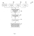
- Figure 2 is a flow diagram of the steps involved in preparing and printing a carbon ink layer
- Figure 3 is a close-up cross-section view through a printed carbon electrode layer without any surface treatment
- Figure 4 is a simplified box diagram of a web manufacturing process incorporating corona discharge equipment, according to the present invention.
- Figure 5 is a flow diagram of the main process steps involved in continuous web printing of test sensors, including corona treatment according to the present invention
- Figure 6 is a perspective view of example equipment for use in corona treatment of printed substrate as part of a continuous web printing process according to the present invention
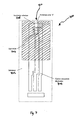
- Figure 7 is a top plan view of a partially printed test sensor that is corona treated during the continuous web printing process of Figures 4 and 5, according to the present invention
- Figure 8 is a simplified cross-section view through the continuous web printing apparatus of Figure 6, showing an example corona treatment apparatus incorporating a single pointed and flat electrode;
- Figure 9 is a simplified cross-section view through the continuous web printing apparatus of Figure 6 showing a further example of a corona treatment apparatus incorporating a plurality of pointed electrodes;
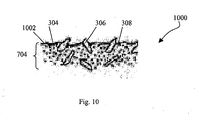
- Figure 10 is a close-up perspective view of the surface of a printed carbon layer with corona discharge surface treatment, according to the present invention.
- Figure 11 is a top plan view of the test sensor of Figure 7 including the enzyme layer;
- Figure 12 is a flow diagram of the main post-web printing processes involved in the manufacture of test sensors, including laying down of adhesive to form a capillary channel;
- Figure 13 is a top plan view of the test sensor of Figures 7 and 11 now including the adhesive layer;
- Figure 14 is a plot of polarization curves comparing printed carbon electrodes with and without corona treatment, according to the present invention.
- Figure 1 is an exploded perspective view of a commercially available test sensor 100 including a base substrate 102, an electrode layer 104, an insulation layer 106, enzyme layers 108, an adhesive layer 110, a layer of hydrophilic film 112 and a cover layer 114.
- Test sensors used in the measurement of analytes or indicators are commonly known in the art.
- the OneTouch Ultra test sensors available from LifeScan Inc., Milpitas, California, used in the measurement blood glucose, which are fully described in patent numbers US6241862B1 , EP1155310B1 , EP1261868B1 and patent application US2003/0217918A1 , the contents of which are fully incorporated herein by reference.
- test sensor 100 of Figure 1 is shown in isolation however in practice an array of test sensors may be screen-printed in card format, each card typically comprising 500 test sensors, or preferably manufactured using a continuous web printing process, whereby the equivalent of approximately 2000 cards of test sensors are screen-printed per batch on a continuous web of substrate material.
- the continuous web printing apparatus is described in detail in patent applications W02004/040287A1 and W02004/039600A2 (both filed October 30, 2003 by the same applicant).
- Patent application WO2004/039898A1 describes an ink composition and method for use thereof in the manufacturing of electrochemical sensors, the entire content of which is fully incorporated herein by reference.
- Electrochemical sensors according to WO2004/039898A1 can be used as a biosensor for the analytical determination of blood glucose, wherein a current is measured at a constant potential and the magnitude of the measured current is indicative of the glucose concentration. The resulting current can be linearly calibrated to output an accurate glucose concentration.
- a method of calibrating electrochemical glucose biosensors is to define multiple calibration codes within a calibration space, in which a particular calibration code is associated with a discrete slope and intercept pair.
- a measured current output may be mathematically transformed into an accurate glucose concentration by subtracting an intercept value from the measured current output and then dividing by the slope value.
- the measured current output, slope and intercept values can be influenced by the electrochemical surface area, overpotential for oxidizing a redox mediator, as well as the stability, resistance and capacitance of the carbon layer that serves as the electrochemical sensor electrode.
- FIG 2 is a flow diagram 200 of the main steps involved in preparing and printing electrode layer 104 of Figure 1.
- carbon black 202 and graphite 204 are mixed together with a polymer 206 and a solvent 207, step 208.
- Solvent 207 keeps the ink in a liquid state, step 210.
- Dispersing the components in a solvent such as Isopherone for example allows batches of carbon ink to be prepared in advance, and may be kept dispersed in the solvent for up to several months prior to use.
- a suitable carbon black include, but is not limited to Vulcan XC-72 (available from Cabot) or Conductex 975B (available from Sevalco).
- Suitable graphites include, but are not limited to Timrex KS15 carbon (available from G & S Inorganics). Further examples are provided in W02004/039898A1 .
- the solvent 207 is removed by heating the liquid ink to temperatures in the range of 120 to 160 degrees, step 214. As the solvent evaporates at the exposure temperature, the carbon black, graphite and polymer particles, which were previously well dispersed in the solvent, are forced to come together as the material shrinks thereby decreasing the electrical resistance of the carbon composite ink. Removal of the solvent transforms the liquid ink into a paste that reliably adheres to substrate material 102, step 214.
- ink compositions can be utilized in the process of manufacturing electrochemical sensors, particularly those that provide beneficial electrochemical and physical characteristics e.g. electrochemical surface area, resistance, capacitance and stability, while also being compatible with relatively high-speed continuous web processing techniques as will be described in relation to Figure 4.
- Figure 3 is a close-up cross-section view 300 through a printed carbon electrode layer 302 without any surface treatment, including carbon black particles 304, graphite particles 306, a polymer resin 308 and a thin film 312 of polymer 308 at the surface 310 of electrode 302.
- the ink composition should be dryable in a drying duration that does not limit the speed of the continuous web process e.g. a drying duration in the range 30 to 60 seconds.
- a drying duration in the range 30 to 60 seconds.
- Such a short drying duration requires application of quite harsh drying conditions e.g. the use of 140 °C air at a velocity of 60 m 3 /minute.
- the combination of severe drying conditions and conventional ink compositions i.e. a carbon, graphite and polymer composite can result in the formation of an electrode (e.g. a carbon electrode) with poor electrochemical properties.
- Figure 3 shows a cross-section 300 through a screen-printed carbon electrode that has not received any surface treatment such as item 104 of Figure 1, showing carbon 304 and graphite 306 particles entrained within a polymer resin 308.
- Polymer 308 is required to bind carbon particles 304 and graphite particles 306 together to provide the required conductive properties.
- Use of a polymer 308 can however compromise the electrochemical properties of analyte test sensors as screen-printing with a carbon composite ink formulation may result in deposition of a thin film 312 of polymer 308 over the conductive carbon 304 and graphite 306 components at the surface 310 of the printed electrode layer 302.
- the electrochemical reaction of electrochemical test sensors occurs at the surface 310 of conductive electrodes 302, therefore the presence of a thin film 312 of polymer 308 over the carbon 304 and graphite 306 components can be inhibitory to the electron exchange properties of these elements.
- Thin film 312 may reduce the effectiveness of the surface exchange electrons and decrease the ability of the test sensor to respond accurately to glucose concentrations particularly in low temperature conditions. It is therefore an aim of the present invention to incorporate a surface treatment process to substantially remove thin film 312 of polymer 308 from the active surfaces of carbon 304 and graphite 306 components in order to improve the electrochemical properties of conductive electrode 302.
- FIG. 4 is a simplified box diagram showing the general layout of a continuous web printing apparatus 400 incorporating corona discharge surface treatment equipment according to the present invention, including an unwinder unit 402, a substrate 404, a preconditioning station 406, an electrode print station 408, a first dryer 410, an insulation print station 412, a second dryer 414, a corona treatment unit 600 (described in detail in relation to Figure 6), a first enzyme print station 416, a third dryer 418, a second enzyme print station 420, a fourth dryer 422, a rewinder roller 424 and arrows 'B' to again indicate the direction of travel of substrate 404.
- an unwinder unit 402 a substrate 404
- a preconditioning station 406 an electrode print station 408
- a first dryer 410 an insulation print station 412
- a second dryer 414 a corona treatment unit 600 (described in detail in relation to Figure 6)
- a first enzyme print station 416 a third dryer 418, a
- corona discharge is well known particularly in the printing industry to facilitate bonding of plastic materials to metals or other plastic materials, or to simply enable printing onto a plastic surface.
- the liquid or ink being printed requires to 'wet' the surface of the substrate being printed upon. 'Wettability' depends on the surface energy, also referred to as the surface tension of the substrate.
- Surface modification pretreatment such as corona discharge can improve wettability of a material by raising the surface energy thereby facilitating adhesion properties by creating bonding sites. To obtain optimum adhesion, it is necessary to increase the surface energy of the substrate to just above that of the liquid or ink to be applied.
- Corona treatment is an electrical process that uses ionized air to increase the surface tension of non-porous substrates i.e. corona treatment converts the surface from a non-polar state to a polar state.
- Typical corona treatment systems operate at electrical voltages in the region of 1 to 10kV.
- the high voltage of corona discharge causes the free electrons in air to accelerate and cause ionization.
- collisions of high velocity electrons with air molecules results in electron avalanching.
- the electrons bombard the surface with energies up to 2 or 3 times greater than the energy required to break the molecular bonds of the material surface.
- Corona discharge treatment differs from plasma discharge in that corona uses ionized air whereas plasma discharge involves the electrical ionization of a gas e.g. pure oxygen or nitrogen. Plasma discharge is also typically created at much lower voltage levels.
- corona treatment unit 600 of Figure 6 enables easy installation to existing high-speed printing lines, such as the embodiment of a continuous web printing apparatus of Figure 4 without requiring significant modifications.
- Substrate 404 such as Melinex® ST328 (manufactured by DuPont Teijin Films) may be supplied in a roll format nominally 350 microns thick by 370mm wide and approximately 660m in length.
- Substrate 404 may include an acrylic coating on one or both sides to improve ink adhesion.
- Preconditioning unit 406 may be used to precondition substrate material 404 at a sufficiently high temperature (up to 185 °C) so that in one example, irreversible stretch (approximately 0.7mm per artwork repeat) of the substrate is substantially removed, optionally while also under tension, prior to the substrate undergoing the printing process. Preconditioning the substrate material 404 improves stability and ensures that substrate 404 experiences minimum dimensional distortion during the web printing process.
- polyester and indeed Melinex® are described in this embodiment, the use of other materials can be envisaged by those skilled in the art such as, for example, nylon, polycarbonate, polyimide, polyvinylchloride, polyethylene, polypropylene, PETG, or polyester. Variations in dimensions and thickness will also be apparent to those skilled in the art.
- substrate unwind unit 402 may be a Martin Unwinder/Automatic Splice, available from Martin Automatic Inc. in Rockford, IL.
- Preconditioning station 406, electrode print station 408, insulation print station 412, first enzyme print station 416 and second enzyme print station 420 may all be encompassed within a modified Kammann Printer, available from Werner Kammann maschinefabrik Gmbh, model number K61, in Bunde, Germany, and indeed further modified to include a corona treatment unit 600 according to the present invention.
- Rewinder unit 424 may be a Martin Rewinder for example, available from Martin Automatic Inc. in Rockford, IL. While specific models of apparatus are provided as examples, these may be varied and/or replaced and/or omitted altogether without departing from the scope of the invention as will be understood by those skilled in the art.
- FIG. 4 shows corona treatment unit 600 placed after the deposition of the carbon electrode and insulation layers of the test sensor (print stations 408 and 412) and immediately prior to the subsequent deposition of the enzyme layer(s) at print stations 416 and 420.
- This position in the sequence of events comprising a continuous web printing apparatus ensures that all surfaces to receive enzyme deposition are present and subjected to the corona discharge surface treatment prior to deposition of the enzyme layer.
- FIG. 5 is a flow diagram 500 of the main process steps involved in the continuous web printing process 400 incorporating corona treatment of Figure 4.
- a roll of substrate 404 is placed into printing apparatus 400 and unwound at unwind station 402, step 502.
- substrate 404 is optionally pretreated, step 504.
- the carbon electrode layer is printed at station 408, step 506, followed by drying, step 508.
- Insulation ink in then printed upon the carbon layer, step 510, and again progresses through a drying station, step 512.
- the printed substrate passes through a corona treatment unit 600 (described in detail in relation to Figure 6), step 514, prior to deposition of subsequent enzyme layers, step 516.
- a drying station typically follows each printing station, step 518, to ensure that ink deposited is sufficiently dry to accept a subsequent layer thereupon.
- the printed substrate 404 is rewound and transferred for further processing, step 520.
- test sensors are manufactured using a continuous web printing apparatus, it is convenient to implement corona discharge surface treatment as part of this continuous process, so that the characteristics of the surface are reproducible and ensured by the treatment process i.e. variation is not introduced by additional variables added to the manufacturing process.
- the level of corona treatment can be controlled by varying the speed of travel of the web substrate, thereby controlling the time that the treated area is exposed to the corona discharge. Furthermore, the distance between the positive and negative electrodes of the corona discharge apparatus can be modified to optimize the level of treatment as described in Figure 6. Optimization of the process ensures that all cards of test sensors in a printed batch receive the same, uniform level of treatment.
- Corona discharge apparatus 600 is placed within continuous printing apparatus 400 after the insulation drying station 414 and before the first enzyme printing station 416. This way, the treated surface is not exposed to organic solvent after treatment, and the treated surface immediately receives a layer of enzyme ink. Printing immediately after surface treatment maximizes the effect.
- FIG. 6 is a perspective view of an example corona treatment unit 600 for surface treating printed substrate as part of the continuous web printing process described in relation to Figures 4 and 5.
- Corona treatment unit 600 includes a high frequency generator 602, a high voltage transformer 604, a power line 616, an ozone extraction pipe 618, an insulated electrode housing 606 with a pointed electrode therein (not seen), an air gap 'A', a flat electrode 608 connected to earth, a roller 610, pre-corona treatment printed substrate 612, post-corona treatment substrate 614, an arrow 'B' indicating the direction of movement of web substrate 612, 614 and an arrow 'C' indicating the direction of subsequent printing and processing of corona treated web substrate 614.
- Corona discharge units such as the example shown in Figure 6 are commercially available, such as the CLN Corona Station available from Softal Electronics, Hamburg, Germany.
- printed substrate 612 enters corona treatment unit 600 in a direction indicated by arrow 'B'.
- Printed substrate 612 comprises a plurality of partially printed test sensors, such as test sensor 700 of Figure 7 for example.
- Printed substrate 612 travels over flat electrode 608 through air gap 'A' situated directly beneath insulated electrode housing 606. Frequency generator 602 and high voltage transformer 604 communicate with insulated electrode housing 606 via power line 616. As printed substrate 612 passes through gap 'A' it is subjected to the intense electric field of corona discharge generated between a thin, pointed electrode located within insulated housing 606 and flat electrode 608 that is connected to earth. Post-corona treatment substrate 614 leaves corona treatment station 600 and progresses for further processing in a direction indicated by arrow 'C'.
- a corona treatment station such as unit 600 of Figure 6 is capable of achieving an operating speed of up to 500m per minute, and the degree of pretreatment is controllable by varying the web speed and/or power rating of the corona discharge.
- Typical operating speeds according to the present invention are in the range of 2 to 20 metres per minute, with an operating power of around 0.5 to 2 kW.
- Ozone generated by the corona discharge treatment is removed by extraction pipe 618.
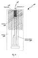
- Figure 7 is a top plan view of a partially printed test sensor 700 that receives corona discharge treatment as part of the continuous web printing process outlined in relation to Figures 4 to 6, including a bare substrate 702, a carbon electrode print 704, an insulation print 706 with an open rectangular channel 708 to define an area of carbon electrodes exposed to a fluid sample and an area of substrate 'S' located above the carbon print 104 at the entrance to capillary channel 710.
- Figure 7 shows a partially printed test sensor 700, isolated from the continuous web of printed test sensors (items 612, 614 in Figure 6) to more clearly show the printed layers that are subjected to corona discharge at corona treatment unit 600.
- test sensor 700 progresses through pretreatment unit 406, carbon print station 408, first dryer 410, insulation print station 412 and second drying station 414 prior to reaching corona treatment unit 600.
- test sensor 700 has received carbon print layer 704 and insulation print layer 706.
- insulation layer 706 may be Ercon E6110-116 Jet Black Insulayer Ink available from Ercon, Inc.
- corona treatment unit 600 provides a blanket treatment across the printed web 612 of Figure 6, subjecting all areas of test sensor 700 to the same level of surface ionization.
- corona surface treatment improves adhesion of subsequent material deposition onto the treated surfaces.
- exposed areas of substrate 702, carbon electrodes 704 and insulation 706 all receive corona discharge treatment when passed through corona treatment unit 600.
- the treated surfaces of substrate 602 including area 'S', carbon electrodes 604 and insulation 606 become modified by the corona discharge, and rendered more ready to accept subsequent deposition e.g. an enzyme layer at printing stations 416 and 420 of Figure 4.
- the position of enzyme layer 1102 is shown and described in relation to Figure 11.
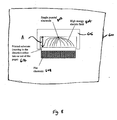
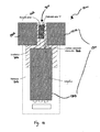
- Figure 8 is a simplified cross-section view through corona treatment unit 600 of Figure 6 that forms part of the continuous web printing process of Figure 4, including a single pointed treating electrode 802 within an insulated electrode housing 606, a flat counter electrode 608, a high energy electric field 804 and a printed substrate 614.
- corona treatment station 600 is designed around just two electrodes, a single, very thin, pointed treating electrode 802 and a flat, counter electrode 608 (typically at ground potential). Basically, corona discharge occurs when an electric current passes through an air gap between asymmetrical electrodes such as pointed electrode 802 and flat electrode 608.
- the example embodiment of a corona treatment unit 600 provided is typically open to the atmosphere, allowing ambient air into gap 'A'.
- An intense electric field 804 is generated by application of a high voltage between pointed treating electrode 802 located within insulated housing 606, and flat counter electrode 608.
- the corona discharge is sustained between treating electrode 802 and flat electrode 608 by establishment of such a high potential difference there between.
- Ceramic insulator assemblies are typically present to ensure insulation of the high voltage corona.
- Corona discharge at frequencies of 15 to 25 kHz provides high efficiency energy transfer as electrons oscillate in air gap 'A' between the asymmetric electrodes.
- the top layer may 'spark' as the molecular bonds break, leaving the carbon electrode surface exposed virtually free of chemistry inhibiting polymer.
- This method of surface treatment is based on the principle of high voltage discharge through air or alternatively under vacuum pressure, and provides a uniform treatment of materials passing through the discharge area.
- Corona treatment units such as the example provided in Figure 6 may be able to treat substrates at a rate of up to 500 metres per minute.
- Figure 9 is a simplified cross-section view through a further example embodiment of a corona treatment unit 600 forming part of the continuous web printing process of Figure 4, including a plurality of pointed electrodes 902 within an insulating electrode housing 606, a flat electrode 608, a high energy electric field 904 and a printed substrate 614.
- the example embodiment of a corona treatment unit 600 of Figure 9 optionally comprises the same number of pointed, treatment electrodes 902 as the number of rows of test sensors on each card being processed through the continuous web printing apparatus. Segmented treatment electrodes 902 or multi-blade electrodes may optionally be used for corona discharge treatment of individual rows of test sensors. In this type of system, the corona power is distributed over a number of parallel electrodes to obtain an even corona with many small sparks. This may be more efficient than the regular single treatment electrode 802 described in relation to Figure 8.
- Figure 10 is a close-up cross-section view 1000 through carbon electrode layer 704 of Figure following exposure to corona discharge according to the present invention, including carbon particles 304, graphite particles 306, a polymer 308 and a top surface 1002.
- the cross-section view 1000 through carbon electrode 704 of Figure 10 is similar to the cross-section view of Figure 3 (pre-corona treatment), however there is a substantial difference in the surface characteristics between them.
- the close-up view of Figure 10 shows carbon 304 and graphite particles 306 clearly exposed at surface 1002 i.e. there is no thin layer of polymer material covering the carbon particles.
- the electrochemical surface area of a carbon electrode is represented by the portion of carbon electrode 704 that contributes to the oxidation of the mediator.
- Graphite 306, carbon black 304 and polymer 308 e.g. resin have varying degrees of conductivity and therefore influence the proportion of the geometric electrode area that can participate in the oxidation of a mediator.
- This geometric area represents the area of carbon electrodes 704 that are exposed to a liquid sample e.g. blood within the capillary channel that can be seen more clearly in Figure 13.
- the current output of a glucose biosensor is directly proportional to the electrochemical surface area.
- Corona treatment unit 600 shown in detail in Figure 6 and as part of a continuous web printing process of Figure 4 has the effect of removing thin layer 312 of polymer material from the surface of carbon electrode 704. Removal of thin layer of polymer 312 from carbon electrode 704 creates surface 1002 whereby the top layer of polymer 308 is removed or carbonized by the corona discharge treatment leaving clean carbon particles 304 exposed at surface 1002 of carbon electrode 704. Treatment by corona discharge is relatively fast, in the order of 1 second, therefore it only changes the surface characteristics and does not affect the bulk of the carbon ink.
- Fast exposure of a material to a high energy density environment such as corona discharge removes the more unstable components from the surface e.g. polymer 308 in this example, and/or any other component absorbed by the carbon ink during the printing and drying process. Exposing the carbon composite of carbon electrodes 704 to corona discharge leaves graphite 306 and carbon black particles 304 exposed at surface 1002 thereby enhancing the electrochemical properties of the conductive carbon electrodes. In addition, as the high energy density corona discharge oxidizes the exposed materials, a more hydrophilic surface is produced that facilitates adhesion of the subsequent enzyme layer.
- Figure 11 is a top plan view of a test sensor 1100 that has undergone corona treatment according to the present invention, and has received subsequent deposition of an enzyme layer 1102.
- Test sensor 1100 includes all the same elements as test sensor 700 of Figure 7 with the addition of enzyme layer 1102. Examples of possible reagent formulations or inks that may be used for enzyme layer 1102 can be found in US patents US5708247 and US6046051 ; published international applications WO01/67099 and WO01/73124 , all of which are incorporated by reference herein.
- Deposition of enzyme 1102 occurs after corona treatment unit 600 of continuous web printing apparatus 400 of Figure 4.
- a first enzyme layer 1102 is deposited at printing station 416.
- the printed substrate then passes through drying station 418 before a second enzyme layer is optionally deposited over the first at print station 420.
- Reliable functioning of electrochemical test sensors such as test sensor 100 of Figure 1, requires that enzyme layer(s) 1102 be printed over the carbon electrodes 704, substrate 702 including area 'S', and insulation ink 706 as shown in Figure 11.
- Corona treatment of test sensor 700 increases the wettability or surface tension of the surface areas exposed i.e. substrate 702 including area 'S', carbon electrodes 704 and insulation layer 706.
- Corona treatment of test sensor 700 ( Figure 7) therefore substantially improves the adhesion of enzyme ink 1102 to the carbon electrodes 704, insulation ink 706 and substrate 702 including area 'S' enhancing the adhesion of the enzyme layer around the entrance to capillary channel 710.
- Figure 12 is a flow diagram 1200 of the remaining process steps involved in the manufacture of electrochemical test sensors.
- the continuous web printing apparatus of Figure 4 may only partially manufacture test sensors according to the present invention. The remaining process steps are outlined in Figure 12.
- the roll of printed substrate is removed and transferred for further processing.
- the roll of printed substrate is cut into cards, step 1202.
- Cards of test sensors typically comprise approximately 500 individual test sensors.
- an adhesive layer (item 110 in Figure 1) is applied, step 1204, followed by lay down of a hydrophilic film and final cover layer (items 112 and 114 in Figure 1) step 1206.
- Each card of test sensors is then cut into individual test sensors, step 1208, and finally a predetermined number of test sensors is then placed into a form of packaging such as a desiccated vial, step 1210.
- Figure 13 is a top plan view of a test sensor 1300 that is equivalent to test sensor 1100 of Figure 11, now showing the addition of an adhesive layer 1301, comprising adhesive pads 1302 and an adhesive stripe 1304.
- Adhesive layer 1301 may be a pressure sensitive adhesive such as a water-based acrylic copolymer adhesive, available from Apollo Adhesives for example, deposited on three sides of enzyme layer 1102.
- the example embodiment of Figure 13 shows adhesive layer 1301 comprising two adhesive pads 1302 and an adhesive stripe 1304. After drying, adhesive layer 1301 forms a spacer of approximately 150 ⁇ m in height, thereby defining three sides of sample capillary channel 710.
- a hydrophilic film 112 such as 3M 9962, a 100 micron thick surfactant-treated optically clear polyester film for example
- cover layer 114 as seen in Figure 1, form the fourth and final side of the sample receiving capillary chamber 710.
- Corona treatment of test sensor 700 of Figure 7 increases the surface tension of all components exposed, thereby improving adhesion of subsequent materials. Corona treatment therefore enhances the adhesion of adhesive layer 1301 to insulation layer 706 and exposed substrate 702 to form part of capillary channel 710.
- the components comprising capillary channel 710 i.e. adhesive layer 1310 and hydrophilic layer 112 are not present at the time of the corona treatment.
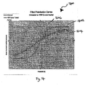
- Figure 14 is a plot of fitted polarization curves 1400 comparing screen-printed carbon electrodes with corona treatment 1402 according to the present invention, against the polarization curve obtained from a carbon electrode without exposure to corona treatment 1404, and also a polarization curve of a gold electrode 1406.
- Figure 14 shows the effect that corona discharge treatment has on the polarization curve of printed carbon electrodes.
- a corona treated carbon electrode provides a polarization curve 1402 that is substantially closer to this optimal curve than the curve obtained from an un-treated carbon electrode. This improvement in polarization is due to the removal of the thin layer of polymer material that resides at the surface of the conductive carbon electrode during the screen-printing process.
- a first advantage of using corona discharge surface treatment in the manufacture of electrochemical test sensors according to the present invention is removal of a component of a carbon composite screen-printed electrode i.e. polymer resin in the example provided herein. Removal of a thin film of insulating material from the surface of the conducting carbon electrodes substantially improves the electrochemical properties during their use in analyte detection and measurement.
- Incorporating blanket corona treatment at a specific point in the manufacture of test sensors provides a further advantage of the present invention.
- Corona treatment increases the wettability or surface tension of the materials exposed, improving adhesion of enzyme ink to printed carbon, insulation ink and substrate polymer material. Improved adhesion of enzyme ink to the substrate virtually eliminates the possibility of the enzyme ink peeling away at the entrance to the capillary channel during the singulation procedure.
- corona treatment of the insulation ink improves the subsequent adhesion of the adhesive layer that is an important component in the formation of the capillary channel structure.
Landscapes
- Life Sciences & Earth Sciences (AREA)
- Health & Medical Sciences (AREA)
- Chemical & Material Sciences (AREA)
- Physics & Mathematics (AREA)
- Biochemistry (AREA)
- Hematology (AREA)
- Chemical Kinetics & Catalysis (AREA)
- Electrochemistry (AREA)
- Biophysics (AREA)
- Analytical Chemistry (AREA)
- Molecular Biology (AREA)
- General Health & Medical Sciences (AREA)
- General Physics & Mathematics (AREA)
- Immunology (AREA)
- Pathology (AREA)
- Apparatus Associated With Microorganisms And Enzymes (AREA)
- Carbon And Carbon Compounds (AREA)
- Electrodes For Compound Or Non-Metal Manufacture (AREA)
Applications Claiming Priority (1)
| Application Number | Priority Date | Filing Date | Title |
|---|---|---|---|
| US11/553,547 US20080164142A1 (en) | 2006-10-27 | 2006-10-27 | Surface treatment of carbon composite material to improve electrochemical properties |
Publications (2)
| Publication Number | Publication Date |
|---|---|
| EP1916309A2 true EP1916309A2 (fr) | 2008-04-30 |
| EP1916309A3 EP1916309A3 (fr) | 2010-11-24 |
Family
ID=39113570
Family Applications (1)
| Application Number | Title | Priority Date | Filing Date |
|---|---|---|---|
| EP07254257A Withdrawn EP1916309A3 (fr) | 2006-10-27 | 2007-10-26 | Traitement de surface de matériel composite en carbone pour améliorer les propriétés électrochimiques |
Country Status (2)
| Country | Link |
|---|---|
| US (1) | US20080164142A1 (fr) |
| EP (1) | EP1916309A3 (fr) |
Cited By (5)
| Publication number | Priority date | Publication date | Assignee | Title |
|---|---|---|---|---|
| CN101676718A (zh) * | 2008-09-17 | 2010-03-24 | 霍夫曼-拉罗奇有限公司 | 测定液体样本内的分析物的设备及方法 |
| WO2012025711A1 (fr) * | 2010-08-23 | 2012-03-01 | Lifescan Scotland Limited | Encres réactives enzymatiques pour l'utilisation dans des bandelettes d'essai ayant un code de calibration prédéterminé |
| CN105683742A (zh) * | 2013-06-10 | 2016-06-15 | 豪夫迈·罗氏有限公司 | 制造测试元件的方法和设备 |
| CN108603857A (zh) * | 2016-03-11 | 2018-09-28 | 松下知识产权经营株式会社 | 电化学测定系统、电化学测定装置以及电化学测定方法 |
| CN108700541A (zh) * | 2015-12-22 | 2018-10-23 | 加泰罗尼亚理工大学 | 电化学传感器和涂覆方法、制造方法以及相应的用途 |
Families Citing this family (6)
| Publication number | Priority date | Publication date | Assignee | Title |
|---|---|---|---|---|
| CN102297885A (zh) * | 2010-06-25 | 2011-12-28 | 厚美德生物科技股份有限公司 | 具有微通道的生物感测试片结构 |
| TWI539157B (zh) * | 2011-11-15 | 2016-06-21 | 五鼎生物技術股份有限公司 | 電化學血液檢測試片及其診斷系統 |
| US9372129B2 (en) * | 2014-06-26 | 2016-06-21 | Quarkonics Applied Research Corporation | Pressure and flow detection sensor including a carbon-based element |
| WO2019040728A1 (fr) * | 2017-08-23 | 2019-02-28 | Mayo Foundation For Medical Education And Research | Biocapteur et structure de circuit en graphite et leur procédé de fabrication |
| JP7521290B2 (ja) * | 2019-10-09 | 2024-07-24 | artience株式会社 | 酵素センサー電極形成用組成物、酵素センサー用電極及び酵素センサー |
| CN110831307B (zh) * | 2019-11-20 | 2022-04-29 | 武汉理工大学 | 油品电荷注入装置及其使用方法 |
Citations (8)
| Publication number | Priority date | Publication date | Assignee | Title |
|---|---|---|---|---|
| US5708247A (en) | 1996-02-14 | 1998-01-13 | Selfcare, Inc. | Disposable glucose test strips, and methods and compositions for making same |
| US6046051A (en) | 1997-06-27 | 2000-04-04 | Hemosense, Inc. | Method and device for measuring blood coagulation or lysis by viscosity changes |
| US6241862B1 (en) | 1996-02-14 | 2001-06-05 | Inverness Medical Technology, Inc. | Disposable test strips with integrated reagent/blood separation layer |
| WO2001067099A1 (fr) | 2000-03-08 | 2001-09-13 | Inverness Medical Limited | Mesure de substances liquides |
| WO2001073124A2 (fr) | 2000-03-28 | 2001-10-04 | Diabetes Diagnostics, Inc. | Capteur de glucose a reponse rapide |
| US20030217918A1 (en) | 2000-03-28 | 2003-11-27 | Davies Oliver William Hardwicke | Rapid response glucose sensor |
| WO2004039898A1 (fr) | 2002-10-30 | 2004-05-13 | Inverness Medical Limted | Composition d'encre et procede d'utilisation de celle-ci dans la fabrication de capteurs electrochimiques |
| WO2004040287A1 (fr) | 2002-10-30 | 2004-05-13 | Inverness Medical Limited | Procede de fabrication de sondes electrochimiques |
Family Cites Families (8)
| Publication number | Priority date | Publication date | Assignee | Title |
|---|---|---|---|---|
| DK0759950T3 (da) * | 1994-05-19 | 2000-10-30 | Minnesota Mining & Mfg | Polymer genstand med forbedret hydrofili og en fremgangsmåde til fremstilling deraf |
| US5997817A (en) * | 1997-12-05 | 1999-12-07 | Roche Diagnostics Corporation | Electrochemical biosensor test strip |
| US6103033A (en) * | 1998-03-04 | 2000-08-15 | Therasense, Inc. | Process for producing an electrochemical biosensor |
| US6408755B1 (en) * | 1999-08-31 | 2002-06-25 | Agfa-Gavaert | Method for erasing a lithographic printing master |
| US6749887B1 (en) * | 2001-11-28 | 2004-06-15 | Lifescan, Inc. | Solution drying system |
| US8071030B2 (en) * | 2003-06-20 | 2011-12-06 | Roche Diagnostics Operations, Inc. | Test strip with flared sample receiving chamber |
| CN101091114A (zh) * | 2004-08-31 | 2007-12-19 | 生命扫描苏格兰有限公司 | 制造自动校准传感器的方法 |
| US20070259431A1 (en) * | 2004-09-20 | 2007-11-08 | Charlton Steven C | Optical Sensor and Methods of Making It |
-
2006
- 2006-10-27 US US11/553,547 patent/US20080164142A1/en not_active Abandoned
-
2007
- 2007-10-26 EP EP07254257A patent/EP1916309A3/fr not_active Withdrawn
Patent Citations (11)
| Publication number | Priority date | Publication date | Assignee | Title |
|---|---|---|---|---|
| US5708247A (en) | 1996-02-14 | 1998-01-13 | Selfcare, Inc. | Disposable glucose test strips, and methods and compositions for making same |
| US6241862B1 (en) | 1996-02-14 | 2001-06-05 | Inverness Medical Technology, Inc. | Disposable test strips with integrated reagent/blood separation layer |
| US6046051A (en) | 1997-06-27 | 2000-04-04 | Hemosense, Inc. | Method and device for measuring blood coagulation or lysis by viscosity changes |
| EP1155310B1 (fr) | 1999-01-12 | 2006-01-04 | Diabetes Diagnostics, Inc. | Bandelettes de test jetables a couche de separation reactif/sang integree |
| WO2001067099A1 (fr) | 2000-03-08 | 2001-09-13 | Inverness Medical Limited | Mesure de substances liquides |
| EP1261868B1 (fr) | 2000-03-08 | 2005-10-19 | Inverness Medical Limited | Mesure de substances liquides |
| WO2001073124A2 (fr) | 2000-03-28 | 2001-10-04 | Diabetes Diagnostics, Inc. | Capteur de glucose a reponse rapide |
| US20030217918A1 (en) | 2000-03-28 | 2003-11-27 | Davies Oliver William Hardwicke | Rapid response glucose sensor |
| WO2004039898A1 (fr) | 2002-10-30 | 2004-05-13 | Inverness Medical Limted | Composition d'encre et procede d'utilisation de celle-ci dans la fabrication de capteurs electrochimiques |
| WO2004040287A1 (fr) | 2002-10-30 | 2004-05-13 | Inverness Medical Limited | Procede de fabrication de sondes electrochimiques |
| WO2004039600A2 (fr) | 2002-10-30 | 2004-05-13 | Inverness Medical Limited | Humidification du poste d'impression enzymatique lors d'un procede continu de production de capteurs electrochimiques |
Cited By (12)
| Publication number | Priority date | Publication date | Assignee | Title |
|---|---|---|---|---|
| CN101676718A (zh) * | 2008-09-17 | 2010-03-24 | 霍夫曼-拉罗奇有限公司 | 测定液体样本内的分析物的设备及方法 |
| EP2166352A1 (fr) * | 2008-09-17 | 2010-03-24 | F.Hoffmann-La Roche Ag | Dispositif et procédé destinés à la détermination d'un analyte dans un échantillon de liquide |
| JP2010071992A (ja) * | 2008-09-17 | 2010-04-02 | F Hoffmann La Roche Ag | 液体サンプル中の分析物を測定するための装置及び方法 |
| US8210031B2 (en) | 2008-09-17 | 2012-07-03 | Roche Diagnostics Operations, Inc. | Device and method for the determination of an analyte in a sample of liquid |
| WO2012025711A1 (fr) * | 2010-08-23 | 2012-03-01 | Lifescan Scotland Limited | Encres réactives enzymatiques pour l'utilisation dans des bandelettes d'essai ayant un code de calibration prédéterminé |
| US8409412B2 (en) | 2010-08-23 | 2013-04-02 | Lifescan Scotland, Ltd. | Enzymatic reagent inks for use in test strips having a predetermined calibration code |
| CN105683742A (zh) * | 2013-06-10 | 2016-06-15 | 豪夫迈·罗氏有限公司 | 制造测试元件的方法和设备 |
| CN105683742B (zh) * | 2013-06-10 | 2018-12-25 | 豪夫迈·罗氏有限公司 | 制造测试元件的方法和设备 |
| CN108700541A (zh) * | 2015-12-22 | 2018-10-23 | 加泰罗尼亚理工大学 | 电化学传感器和涂覆方法、制造方法以及相应的用途 |
| EP3396367A4 (fr) * | 2015-12-22 | 2020-01-15 | Universitat Politècnica De Catalunya | Capteur électrochimique et procédé de revêtement, procédé de fabrication et utilisations associés |
| US11067528B2 (en) | 2015-12-22 | 2021-07-20 | Universitat Politècnica De Catalunya | Electro-chemical sensor and coating method, production method and corresponding uses |
| CN108603857A (zh) * | 2016-03-11 | 2018-09-28 | 松下知识产权经营株式会社 | 电化学测定系统、电化学测定装置以及电化学测定方法 |
Also Published As
| Publication number | Publication date |
|---|---|
| EP1916309A3 (fr) | 2010-11-24 |
| US20080164142A1 (en) | 2008-07-10 |
Similar Documents
| Publication | Publication Date | Title |
|---|---|---|
| Pavinatto et al. | Printed and flexible biosensor for antioxidants using interdigitated ink-jetted electrodes and gravure-deposited active layer | |
| EP0986748B1 (fr) | Electrodes servant a mesurer des substances a analyser dans des specimens presentant un volume limite | |
| US9506891B2 (en) | Making imprinted thin-film electronic sensor structure | |
| US6740214B1 (en) | Microelectrode biosensor and method therefor | |
| Baranski et al. | Potentiometric stripping determination of heavy metals with carbon fiber and gold microelectrodes | |
| US6973706B2 (en) | Method of making a transcutaneous electrochemical sensor | |
| CN1439057A (zh) | 为制造可配置电化学传感器的连续过程 | |
| US9952197B2 (en) | Biosensor comprising electrode for measuring hematocrit value | |
| US20080164142A1 (en) | Surface treatment of carbon composite material to improve electrochemical properties | |
| MXPA04007411A (es) | Tira de biosensor electroquimico para el analisis de muestras liquidas. | |
| AU2007237821A1 (en) | Sensor comprising conducting polymer materials | |
| US20160047766A1 (en) | Imprinted thin-film electronic sensor structure | |
| US10309888B2 (en) | Biosensor comprising electrode for measuring hematocrit value | |
| Yuen et al. | Electrolyte-sensing transistor decals enabled by ultrathin microbial nanocellulose | |
| US20250027928A1 (en) | Optically transparent microelectrode arrays for electrochemical and electrophysiological measurements or stimulation | |
| EP2174120A1 (fr) | Électrochimie des nanotubes | |
| JP2014153280A (ja) | バイオセンサ用電極およびバイオセンサ | |
| Shitanda et al. | Fully screen-printed paper-based electrode chip for glucose detection | |
| US20230065235A1 (en) | Printable carbon nanotube-based carbon dioxide sensor | |
| Buendía et al. | Plasma‐treated polyethylene as electrochemical mediator for enzymatic glucose sensors: Toward bifunctional glucose and dopamine sensors | |
| Dobay et al. | Conducting polymer based electrochemical sensors on thick film substrate | |
| US20110017594A1 (en) | Analyte sensor fabrication | |
| HK1117194A (en) | Surface treatment of carbon composite material to improve electrochemical properties | |
| US20060008581A1 (en) | Method of manufacturing an electrochemical sensor | |
| EP0968416A1 (fr) | Procede de fabrication de detecteurs chimiques |
Legal Events
| Date | Code | Title | Description |
|---|---|---|---|
| PUAI | Public reference made under article 153(3) epc to a published international application that has entered the european phase |
Free format text: ORIGINAL CODE: 0009012 |
|
| AK | Designated contracting states |
Kind code of ref document: A2 Designated state(s): AT BE BG CH CY CZ DE DK EE ES FI FR GB GR HU IE IS IT LI LT LU LV MC MT NL PL PT RO SE SI SK TR |
|
| AX | Request for extension of the european patent |
Extension state: AL BA HR MK RS |
|
| REG | Reference to a national code |
Ref country code: HK Ref legal event code: DE Ref document number: 1117194 Country of ref document: HK |
|
| PUAL | Search report despatched |
Free format text: ORIGINAL CODE: 0009013 |
|
| AK | Designated contracting states |
Kind code of ref document: A3 Designated state(s): AT BE BG CH CY CZ DE DK EE ES FI FR GB GR HU IE IS IT LI LT LU LV MC MT NL PL PT RO SE SI SK TR |
|
| AX | Request for extension of the european patent |
Extension state: AL BA HR MK RS |
|
| REG | Reference to a national code |
Ref country code: DE Ref legal event code: R108 |
|
| AKY | No designation fees paid | ||
| REG | Reference to a national code |
Ref country code: DE Ref legal event code: R108 Effective date: 20110720 |
|
| STAA | Information on the status of an ep patent application or granted ep patent |
Free format text: STATUS: THE APPLICATION IS DEEMED TO BE WITHDRAWN |
|
| 18D | Application deemed to be withdrawn |
Effective date: 20110525 |
|
| REG | Reference to a national code |
Ref country code: HK Ref legal event code: WD Ref document number: 1117194 Country of ref document: HK |