EP1916343A2 - Robinet de chasse à action double - Google Patents
Robinet de chasse à action double Download PDFInfo
- Publication number
- EP1916343A2 EP1916343A2 EP07118168A EP07118168A EP1916343A2 EP 1916343 A2 EP1916343 A2 EP 1916343A2 EP 07118168 A EP07118168 A EP 07118168A EP 07118168 A EP07118168 A EP 07118168A EP 1916343 A2 EP1916343 A2 EP 1916343A2
- Authority
- EP
- European Patent Office
- Prior art keywords
- overflow pipe
- drain valve
- valve according
- flush
- housing
- Prior art date
- Legal status (The legal status is an assumption and is not a legal conclusion. Google has not performed a legal analysis and makes no representation as to the accuracy of the status listed.)
- Granted
Links
Images



Classifications
-
- E—FIXED CONSTRUCTIONS
- E03—WATER SUPPLY; SEWERAGE
- E03D—WATER-CLOSETS OR URINALS WITH FLUSHING DEVICES; FLUSHING VALVES THEREFOR
- E03D1/00—Water flushing devices with cisterns ; Setting up a range of flushing devices or water-closets; Combinations of several flushing devices
- E03D1/02—High-level flushing systems
- E03D1/14—Cisterns discharging variable quantities of water also cisterns with bell siphons in combination with flushing valves
- E03D1/142—Cisterns discharging variable quantities of water also cisterns with bell siphons in combination with flushing valves in cisterns with flushing valves
- E03D1/144—Cisterns discharging variable quantities of water also cisterns with bell siphons in combination with flushing valves in cisterns with flushing valves having a single flush outlet and an additional float for delaying the valve closure
-
- E—FIXED CONSTRUCTIONS
- E03—WATER SUPPLY; SEWERAGE
- E03D—WATER-CLOSETS OR URINALS WITH FLUSHING DEVICES; FLUSHING VALVES THEREFOR
- E03D1/00—Water flushing devices with cisterns ; Setting up a range of flushing devices or water-closets; Combinations of several flushing devices
- E03D1/30—Valves for high or low level cisterns; Their arrangement ; Flushing mechanisms in the cistern, optionally with provisions for a pre-or a post- flushing and for cutting off the flushing mechanism in case of leakage
- E03D1/34—Flushing valves for outlets; Arrangement of outlet valves
Definitions
- the invention relates to a drain valve for a cistern, with a housing which is provided with a valve opening defining an outlet opening, an overflow pipe which is provided at its lower end with a cooperating with the valve seat seal, a relative to the overflow tube height adjustable upper float, a lower float, which is pivotally mounted on the housing, and with a trigger device for selectively triggering a partial flush or full flush, wherein the lower float is provided with a stop on which the overflow pipe in a raised, a full flush associated position provided by a at the overflow pipe Head start.
- Drain valves of the two-volume flushing technique generally have a housing with a vertically raisable and lowerable overflow pipe, wherein the lower end of the overflow pipe is provided with a seal with which an outlet opening is closed.
- the lifting of the overflow pipe by means of at least one actuating element, for example in the form of a push button.
- these two-volume drain valves have one bottom float for full flush and an upper float for partial flush (small flush) on. By adjusting the height of the upper float, the amount of flushing water for the partial flush can be adjusted.
- the overflow pipe on a lateral shoulder which cooperates with a lever which is pivotable about a perpendicular to the longitudinal axis of the overflow pipe axis of rotation, wherein the lever is actuated by a guided in a tubular casing, pressure-loaded cable having one end to the Lever and the other end is attached to a slider.
- the slider engage two pushers, which are displaceable against the force of a spring by different lengths ways, the slider is displaceable by a shorter path of triggering a partial flush, while the displaceable by a longer way pusher serves to trigger a full flush. For the triggering of the full flush is thus the displacement of the associated pusher along a relatively long in this drain valve Displacement and thus a relatively high effort required.
- the present invention has for its object to provide a two-volume drain valve of the type mentioned, which allows a particularly comfortable triggering a partial flush and full flush with minimal effort.
- the drain valve according to the invention is characterized in that the upper float is fixed by means of a height adjustment on the overflow pipe and is dimensioned so that he in the dipped state after briefly raising the overflow pipe from the closed position of the overflow pipe by its buoyancy either in a partial flush or full flush assigned Raising position on its own.
- the upper float retains both a partial flush as even with a full flush a set position relative to the overflow pipe at.
- the drain valve according to the invention is characterized by a particularly smooth and comfortable operation. Because after the user has raised the overflow pipe from the closed position by a relatively small stroke, the further stroke movement of the overflow pipe in the partial flush or full flush associated position is independent by the buoyancy of the upper float. The buoyancy of the upper float is used both in the triggering of a partial flush and in the triggering of a full flush to minimize the force applied by the user.
- the drain valve according to the invention makes it possible to considerably reduce the necessary displacement of a push button for triggering a full flush. This results in new interesting design options for actuator plates in the two-volume flushing technology.
- the height adjustment element for the upper float has a rod-shaped portion, wherein at the overflow pipe at least one locking element is formed, on which the rod-shaped portion of the height adjustment is einknüpfbar.
- a groove extending in the longitudinal direction of the overflow pipe with integrally formed latching elements, in which the height adjustment element is inserted in a form-fitting manner, is preferably formed in the jacket surface of the overflow pipe.
- a further advantageous embodiment of the drain valve according to the invention is characterized in that the lower float is suspended via a cantilever mounted on the housing in a housing formed in the housing (control chamber) having at least one upper inlet opening and at least one lower drain opening, wherein the drain opening preferably is provided with a setting element for changing the opening size.
- the lowering of the lower float can be delayed with respect to the decrease in the water level in the cistern, the time delay can be adjusted with the adjusting element associated with the discharge opening. In this way, the time can be shifted at a full flush at which the overflow tube with its projection disengaged from the trained on the lower float stop, and thus adjust the flowing in a full flush in the toilet bowl flushing.
- the chamber in which the lower float is suspended is preferably formed by the housing and a partition wall disposed within the housing.
- the operation of the drain valve according to the invention is particularly reliable when, according to a further advantageous embodiment, the upper float has vertically extending guide ribs, which in vertical extending guide ribs are guided on the inside of the housing.
- the lower float is detachably connected to the pivotable arm.
- Another advantageous embodiment of the drain valve according to the invention is that at the upper end of the overflow pipe attack elements for lifting the overflow pipe are formed, wherein the triggering device for selectively triggering a partial flush or full flush the attack elements associated levers, which are pivotally mounted in a holder, which as Attachment on the drain valve housing is positively pushed.
- the holder with the levers forms a unit that can be quickly and easily assembled and disassembled.
- the levers in the holder comprise two mutually independently pivotable levers with receptacles for connecting Bowden cables, of which one lever is connected to a lever for triggering a partial flush, while the other lever with a lever connected to trigger a full flush.
- the Bowden cables allow a very flexible arrangement and design of the drain valve associated actuator plate.
- designed to train Bowden cables are much more reliable than pressure-loaded cable according to the DE 101 13 115 A1 , which tend to buckling in principle and insofar are prone to failure.
- the respective Bowden cable is preferably provided at its end associated with the actuating plate with a force transducer which converts a force exerted by a push button of the actuating plate compressive force into a tensile force.
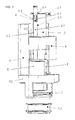
- the drain valve of FIG. 1 is designed as a two-flow drain valve, with both a full flush and a small flush (partial flush) can be triggered.
- the drain valve has a container-like housing part 1, of which in Fig. 1 is shown by a vertical section resulting half.
- a recessed base 1.1 is formed, on which an annular, with the outside of the housing part 1 is substantially flush final housing part 1.2 by latching or otherwise fastened.
- To the lower housing part 1.2 is formed via vertical, angular spacers a pipe socket 1.3, which defines an outlet opening with a valve seat 1.4 and in a pipe socket of a cistern (not shown) is used (see Figures 1 and 3).
- the drain valve further comprises a closure body in the form of an overflow tube 2, which is provided at its lower end with a cooperating with the valve seat 1.4 seal.
- the seal 3 is annular disk-shaped and made for example of rubber or the like. It is held positively in a trained on the overflow pipe 2 annular groove.
- the outer diameter of the overflow tube 2 is substantially smaller than the outer diameter of the valve seat 1.4 and, accordingly, much smaller than the outer diameter of the seal 3.
- the seal 3 thus has a relatively large pressure surface 3.1 for the water column.
- attack elements (attack points) 2.1 are formed for lifting the overflow pipe.
- the attack elements 2.1 are formed as radially projecting from the outside of the overflow pipe 2 pins.
- the drain valve is provided with an upper float 4 and a lower float 5.
- the upper float 4 is attached to an adjustment 6, by means of which the float 4 adjustable in height on the overflow pipe 2 can be fixed.
- the overflow pipe 2 has an undercut groove 2.2 which extends in the axial direction and into which a rod-shaped section 6.1 of the height adjustment element 6 is inserted in a form-fitting manner.
- At the upper end of the rod-shaped portion 6.1 is an angle section 6.2 designed as a handle.
- the groove 2.2 more serving as a detent element depressions (notches) 2.3 are formed.
- the upper float 4 is located in the filled cistern below the water level W (see Fig. 3).
- the upper float 4 is dimensioned so that it opens in the submerged state after briefly raising the overflow pipe 2 from the closed position shown in Figures 1, 2 and 9 by its buoyancy of the drain valve independently, i. the overflow pipe 2 selectively raises in a partial flush or full flush associated position.
- the float 4 retains the position set by means of the height adjustment element 6 relative to the overflow pipe 2, both in the case of a partial flush and in the case of a full flush.
- the upper float 4 is laterally provided with vertically extending guide ribs 4.1, which are guided on vertically extending guide ribs 1.5 on the inside of the container-like housing part 1.
- the guide ribs 4.1, 1.5 are formed on two opposite sides of the float 4 and the housing part 1 (see Figures 2, 4 and 5).
- an opening 1.6 is recessed, which penetrates the overflow pipe 2 with play (see Figures 3 and 5).
- the lower float 5 is pivotally mounted in the housing 1 and provided with a stop 7.1 on which the overflow pipe 2 is seated in a raised, a full flush position by a provided on the overflow pipe 2 projection (notch) 2.4.
- the lower float 5 is releasably attached to a boom 7.
- the boom 7 has a substantially U-shaped section 7.2 with two angled legs 7.3 (see Fig. 6). At the ends of the legs 7.3 connectable to the housing 1 pivot elements 7.4 are formed.
- the swivel elements 7.4 consist of pivot pins which engage in mutually aligned holes 1.7 of the housing 1.
- the axis of rotation of the boom 7 and the float 5 is substantially perpendicular to the vertical longitudinal axis of the overflow pipe second
- the guide ribs 2.5 are arranged diametrically.
- the opening 1.6 in the bottom of the housing part 1 accordingly has two diametrically opposite indentations (extensions) 1.61, 1.62, in which the guide ribs 2.5 of the overflow pipe 2 are accommodated.
- a control edge is formed 7.5, which slides during a partial flush along the guide rib 2.5.
- the Control edge 7.5 is formed on a projection of the leg 7.3 (see Figures 2 and 3).
- the nose-shaped projection 2.4 with which the overflow pipe 2 is seated in a full flush on the stop 7.1 of the boom 7, is integrally formed on the guide rib 2.5 and the lower float 5 faces.
- the lower float 5 is suspended in a chamber (control chamber) 8.
- the chamber 8 is formed by the outer wall and the bottom of the housing 1 and a partition wall 1.8 arranged inside the housing.
- the chamber 8 has an upper inlet opening 8.1 and a lower outlet opening 8.2 (see Figures 4 and 5).
- the discharge opening 8.2 is provided with an adjustment member (not shown) for changing the opening size.
- the adjustment may for example consist of a rotary or sliding closure, a flap or a plug.
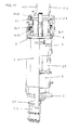
- Fig. 3 the drain valve is shown at the beginning of the full flush.
- the cistern is still filled.
- the water level W is above the fixed to the overflow pipe 2 float 4.
- After triggering the full flush of the float 4 has the overflow pipe 2 with the seal 3 raised by its buoyancy.
- the valve seat 1.4 is free. The water flows from the cistern through the pipe socket 1.3 in the connected toilet bowl.
- the nose-shaped projection (latching point) 2.4 of the overflow pipe 2 is now on the stop 7.1 at the control edge 7.5 of the pivotally mounted boom 7.
- the boom 7 is held by the lower float 5 (control float) in the upper position shown in FIG.
- Fig. 6 the drain valve is shown at the end of the full flush.
- the water level (water level) W in the cistern and in the container-like housing part 1 of the drain valve has dropped, while in the chamber (control chamber) 8 initially a higher water level (water level) W K is present.
- Only after a dependent on the opening size of the discharge opening 8.2 emptying time of the lower float (control float) 5 loses its buoyancy and are about the boom 7 with the control edge 7.5, the overflow pipe with 2 the nose-shaped projection 2.4 free.
- the overflow pipe 2 with the seal 3 attached thereto can now fall down onto the valve seat 1.4 and close the outlet opening.
- the flush volume for the full flush can thus - within certain limits - regardless of the water level in the cistern or drain valve housing 1 can be set.
- the lower float 5 is shown separated from the pivotable boom.
- the lower float 5 is provided with at least one open-topped chamber (pocket) 5.1, which is filled with water during operation. If the control chamber 8 formed in the drain housing 1 is filled with water, then the lower float 5 buoyancy, wherein the water-filled bag is 5.1 neutral in effect. Only after dropping the water level in the control chamber 8, the water-filled bag acts as a weight 5.1 and causes the float 5 tilts the boom 7 with the control edge 7.5 away from the overflow pipe 2 to the side, so that the overflow pipe 2 is released (see FIG. 6).
- a pin-shaped connecting element 5.2 having a diameter-enlarged head is integrally formed or fastened, which can be inserted in a form-fitting manner into a fork-shaped, elastically spreadable leg of the extension arm 7.
- the optional triggering of a full flush or partial flush can be carried out in the two-volume drain valve according to the invention in particular via a Bowden cable drive.
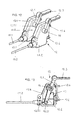
- FIG. 8 shows a holder 9 designed as an attachment, which is mounted on a housing cover 1, which can be latched to the housing part 1 (see FIG. 9).
- a stepped, insertable into the housing part 1 collar 1.91 is formed, the resilient portions or tongues 1.92 comprises, on the outside of which projections are formed, which are latched in recesses 1.10 of the housing 1.
- the cover 1.9 also has a breakthrough 1.93 for the overflow pipe 2.
- the retractable on the cover 1.9 mount 9 is formed substantially U-shaped. It has two substantially vertically and parallel to each other extending wall sections 9.1, 9.2, which are integrally connected to a transverse wall 9.3. On the inner sides of the wall sections 9.1, 9.2 are mutually parallel web sections 9.4 as connecting elements formed, which cooperate with integrally formed on the housing cover 1.9 angle elements and form a releasable, positive and non-positive connection.
- clip elements are preferably provided on the mount 9 and / or the cover 1.9 in order to simplify the functionally correct positioning of the mount 9 relative to the overflow pipe 2.
- a shoulder is formed on the outside 9.31, in which openings for the passage of the pull wires of the Bowden cables 11.1, 11.2 are formed.
- the respective breakthrough has a shoulder on which a sleeve connected to the tubular sheath of the Bowden cable 11.1, 11.2 rests positively.
- the associated with the Bowden cables 11.1, 11.2, arranged between the vertical webs 9.8 levers 10.1, 10.2 are each acting as a trigger element Release lever 10.3 or 10.4 torsionally rigid connected.
- the release levers 10.3, 10.4 are arranged between the vertical wall section 9.1 or 9.2 and the adjacent vertical web 9.8.
- the left lever 10.3 is associated with a two-armed, angle-shaped lever (control lever) 10.5, which is also pivotally mounted on the bracket 9. As can be seen in Figures 9 and 10, the lever is 10.5 with an arm 10.51 on the associated release lever 10.3 touching and slides on the release lever 10.3 when it is pivoted.
- the second arm 10.52 of the lever 10.5 is used when triggering a partial flush as a stop for the overflow pipe 2 integrally formed attack element 2.1.
- the holder 9 is provided with a return spring, which moves the respective lever 10.1 or 10.2 and thus rotationally rigidly connected release lever 10.3 or 10.4 back to a starting position.
- the connected to the lever 10.1 or 10.2 Bowden cable 11.1 or 11.2 is charged only to train.
- the triggering device is connected to an actuating device (not shown) which consists of an actuating plate with two actuating buttons (pushbuttons) displaceably or pivotally mounted thereon.
- the operation keys are usually designed differently sized, wherein the larger of the two operation keys is used to trigger a full flush, while the smaller operation key is associated with the small flush (partial flush).
- a force transducer 12 is arranged between the Actuating button and the respective Bowden cable, which converts a force exerted by the actuating button pressing force into a tensile force (see Figures 12 and 13).
- the force transducer 12 is provided with a holder 13, which has tongue-shaped clip elements (locking elements) 13.6 and is releasably clipped on the back of the actuator plate.
- the force transducer 12 has a first lever 12. 1 and a second lever 12. 2 connected in a torsionally rigid manner, which are pivotably mounted on a common pin 14 of the holder 13.
- At the first lever 12.1 of the actuating button associated plunger 12.3 is hinged.
- the lever has a 12.1 arc-shaped joint shell which engages around a cylinder formed on the plunger 12.3 with more than 180 °, for example about 220 °.
- a rod-shaped section connects.
- a bush-shaped joint eye is formed, which is pushed onto the pivot pin 14 of the holder 13.
- the lever 12.1 is connected via its hinge eye in the region of a hinge eye of the second lever 12.2 with the latter form-fitting and torsionally rigid.
- the second lever 12.2 is provided at its end opposite the hinge eye with a receptacle 12.21 for connecting the pull wire of the Bowden cable 11.1 or 11.2.
- the puller wire has at its ends - as known per se - cast-on or crimped head pieces which can be inserted in a form-fitting manner into the receptacle 12.21 or the receptacle of the lever 10.1 or 10.2 arranged on the drain valve.
- the holder 13 of the force transducer 12 is formed from two detachably connectable housing halves 13.4 and 13.5.
- the shell-shaped housing half 13.4 has on its inner side the pivot pin 14, while the other shell-shaped housing half 13.5 has an aligned with the pivot pin 4 breakthrough 13.51, which penetrates the sleeve-shaped hinge eye of the externally arranged lever 12.1 with radial play.
- the second lever 12.2 is thus pivotally mounted in the holder 13 and encapsulated.
- a lever 12.2 biasing in an initial position return spring 15 is arranged.
- the housing halves 13.4, 13.5 form an opening 13.52 for the passage of the Bowden cable 11.2.
- the opening 13.52 has a shoulder on which a sleeve connected to the tubular sheath of the Bowden cable 11.2 rests in a form-fitting manner (compare Fig. 13).
- the Bowden cables 11.1, 11.2 associated force transducer 12 are mounted on separate brackets (housings) 13.1, 13.2, so that they can be clipped independently of each other at different locations of the actuator plates at differently shaped actuator plates.
- Fig. 11 the drain valve of the partial flush can be seen.
- the levers 10.1 and 10.3 are in this case unconfirmed.
- the lever 10.2 By pulling on the Bowden cable 11.2 the lever 10.2 is pivoted on the lever 10.2, which presses from below against the engagement element 2.1 of the overflow pipe 2 and the overflow pipe 2 raises something.
- the float 4 connected to the overflow pipe 2 drives the overflow pipe upwards. Because the lever 10.5 is not released but is blocked by the lever 10.3, the pin-shaped engagement element 2.1 of the overflow tube 2 comes under the stop 10.5 formed on the lever 10.5.
- the overflow pipe 2 is prevented from floating into the open position associated with a full flush.
- the drain valve closes after the partial flush.
- the amount of water of the partial flush can by means of of the displaceableêtnverstellelements 6 are set in a certain range.
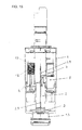
- the lower float 5 and the associated boom 7 is provided with a lever 16.
- the stop, 7.1 on which the projection 2.4 of the overflow pipe 2 is seated in the associated with a full flush position the stop, 7.1 on which the projection 2.4 of the overflow pipe 2 is seated in the associated with a full flush position, the seated projection 2.4 withdrawn. In this way, a full flush can be prematurely terminated.
- the exemplary embodiment illustrated in FIG. 14 corresponds to the so-called flush-stop technique.
- the operation of the lever 16 can in turn be done by means of a Bowden cable.
- FIG. 15 another embodiment of a drain valve according to the invention is shown.
- the upper float 4 is dimensioned so that its buoyancy is greater than the closing force of the overflow pipe 2.
- the water column presses in this case on the seal 3.
- the float 4 is provided with a magnet 17, which is a fixed to the housing of the drain valve electric coil 18 is assigned. A minimal lifting of the fixed at the overflow pipe 2 float 4 separates magnet 17 and electric coil 18, so that the drain valve opens automatically.
- an unlockable lock (not shown) is mounted, by means of which a caused by the upper float 4 upward movement of the overflow pipe 2 can be limited.
- the overflow pipe 2 of the drain valve pushes against the unlockable lock in the upward movement.
- the lock is unlocked.
- Another way of triggering the drain valve is to apply a small, harmless electrical voltage to the electric coil 18, thereby establishing an opposing field to the magnet 17 and thus to reduce the magnetic holding force or dissolve.
- the unlockable lock for partial flushing is switched on or off.
- the execution of the drain valve according to the invention is not limited to the embodiments described above. Rather, numerous variants are conceivable that make use of the concept of the invention contained in the claims even if they deviate.
- the electrical release can be controlled for example via radio or a button, which is in toilets for disabled people, especially in the so-called barrier-free area of advantage.
- the mechanical release in this case is then a practical supplement to the electrical release.
Landscapes
- Health & Medical Sciences (AREA)
- Life Sciences & Earth Sciences (AREA)
- Engineering & Computer Science (AREA)
- Hydrology & Water Resources (AREA)
- Public Health (AREA)
- Water Supply & Treatment (AREA)
- Sanitary Device For Flush Toilet (AREA)
- Mechanically-Actuated Valves (AREA)
Priority Applications (2)
| Application Number | Priority Date | Filing Date | Title |
|---|---|---|---|
| SI200731002T SI1916343T1 (sl) | 2006-10-17 | 2007-10-10 | Dvokoličnski splakovalni ventil |
| PL07118168T PL1916343T3 (pl) | 2006-10-17 | 2007-10-10 | Dwuobjętościowy zawór do spłuczki |
Applications Claiming Priority (1)
| Application Number | Priority Date | Filing Date | Title |
|---|---|---|---|
| DE202006016050U DE202006016050U1 (de) | 2006-10-17 | 2006-10-17 | Zwei-Mengen-Ablaufventil für einen Spülkasten |
Publications (3)
| Publication Number | Publication Date |
|---|---|
| EP1916343A2 true EP1916343A2 (fr) | 2008-04-30 |
| EP1916343A3 EP1916343A3 (fr) | 2010-04-28 |
| EP1916343B1 EP1916343B1 (fr) | 2012-06-13 |
Family
ID=38962079
Family Applications (1)
| Application Number | Title | Priority Date | Filing Date |
|---|---|---|---|
| EP07118168A Active EP1916343B1 (fr) | 2006-10-17 | 2007-10-10 | Robinet de chasse à action double |
Country Status (7)
| Country | Link |
|---|---|
| EP (1) | EP1916343B1 (fr) |
| DE (1) | DE202006016050U1 (fr) |
| DK (1) | DK1916343T3 (fr) |
| ES (1) | ES2388348T3 (fr) |
| PL (1) | PL1916343T3 (fr) |
| PT (1) | PT1916343E (fr) |
| SI (1) | SI1916343T1 (fr) |
Families Citing this family (6)
| Publication number | Priority date | Publication date | Assignee | Title |
|---|---|---|---|---|
| DE102008027225B4 (de) * | 2008-06-06 | 2022-02-24 | GROHEDAL Sanitärsysteme GmbH | Ablaufventil für einen Spülwasserkasten |
| DE202008008739U1 (de) | 2008-07-02 | 2009-11-19 | Viega Gmbh & Co. Kg | Zwei-Mengen-Ablaufventil für einen Spülkasten mit verbessertem Steuerschwimmer-Mechanismus |
| FR2933996B1 (fr) * | 2008-07-16 | 2011-10-14 | Sanitaire Accessoires Services S A S | Dispositif de chasse d'eau permettant un reglage simultane d'un flotteur et d'un tube de trop plein |
| ES2399899B1 (es) * | 2011-01-31 | 2014-02-11 | Fominaya, S.A. | Dispositivo para la descarga de cisternas de inodoros. |
| FR3024474B1 (fr) * | 2014-08-04 | 2017-12-22 | Wirquin Plastiques Sa | Dispositif de vidange d'un reservoir de wc, pour le remplacement d'un dispositif de vidange anterieur, ensemble de renovation et procede de renovation utilisant un tel dispositif |
| US20250146260A1 (en) * | 2023-11-06 | 2025-05-08 | Fluidmaster, Inc. | Cistern system, apparatus and method |
Citations (4)
| Publication number | Priority date | Publication date | Assignee | Title |
|---|---|---|---|---|
| DE29723618U1 (de) | 1997-07-15 | 1998-10-29 | Schwab Sanitär-Plastic GmbH, 72793 Pfullingen | Ablaufarmatur eines Spülkastens |
| DE10113115A1 (de) | 2001-03-16 | 2002-09-19 | Eisenberg Gmbh Sanitaertechnik | Betätigungsvorrichtung für das Ablaufventil eines WC-Spülkastens |
| EP1354100B1 (fr) | 2001-01-23 | 2006-06-07 | Aliaxis R&D S.A.S. | Mecanisme de chasse d'eau pour reservoir de toilettes |
| EP1672130A1 (fr) | 2004-12-15 | 2006-06-21 | Geberit Technik Ag | Soupape d'évacuation d'un réservoir de chasse |
Family Cites Families (7)
| Publication number | Priority date | Publication date | Assignee | Title |
|---|---|---|---|---|
| IL55874A0 (en) * | 1978-11-05 | 1979-01-31 | Raz Zeev | Toilet bowl flush system |
| FR2660338B1 (fr) * | 1990-03-28 | 1992-08-21 | Wirquin Plastiques Sa | Mecanisme de commande de chasses d'eau. |
| FR2676480B1 (fr) * | 1991-05-16 | 1993-08-20 | Tolbert Timothy | Dispositif d'evacuation pour reservoir, a deversement variable. |
| DE29508271U1 (de) * | 1995-05-18 | 1995-08-03 | Hung, Hsiu-Chin, Lu-Kang, Changhua | Toilettenspülvorrichtung |
| FR2740795B1 (fr) * | 1995-11-03 | 1997-12-26 | Ragot Claude | Dispositif a double commande de face de reservoir d'eau |
| ES2204298B1 (es) * | 2002-07-16 | 2005-06-01 | Jose Blanco Gutierrez | Dispositivo de ahorro cuantificado de agua en inodoros por doble descarga controlado por un solo pulsador. |
| US20080295238A1 (en) * | 2005-11-15 | 2008-12-04 | Oakhurst Properties, Llc | Dual Flush Toilet Mechanism |
-
2006
- 2006-10-17 DE DE202006016050U patent/DE202006016050U1/de not_active Expired - Lifetime
-
2007
- 2007-10-10 DK DK07118168.9T patent/DK1916343T3/da active
- 2007-10-10 PT PT07118168T patent/PT1916343E/pt unknown
- 2007-10-10 EP EP07118168A patent/EP1916343B1/fr active Active
- 2007-10-10 SI SI200731002T patent/SI1916343T1/sl unknown
- 2007-10-10 ES ES07118168T patent/ES2388348T3/es active Active
- 2007-10-10 PL PL07118168T patent/PL1916343T3/pl unknown
Patent Citations (4)
| Publication number | Priority date | Publication date | Assignee | Title |
|---|---|---|---|---|
| DE29723618U1 (de) | 1997-07-15 | 1998-10-29 | Schwab Sanitär-Plastic GmbH, 72793 Pfullingen | Ablaufarmatur eines Spülkastens |
| EP1354100B1 (fr) | 2001-01-23 | 2006-06-07 | Aliaxis R&D S.A.S. | Mecanisme de chasse d'eau pour reservoir de toilettes |
| DE10113115A1 (de) | 2001-03-16 | 2002-09-19 | Eisenberg Gmbh Sanitaertechnik | Betätigungsvorrichtung für das Ablaufventil eines WC-Spülkastens |
| EP1672130A1 (fr) | 2004-12-15 | 2006-06-21 | Geberit Technik Ag | Soupape d'évacuation d'un réservoir de chasse |
Also Published As
| Publication number | Publication date |
|---|---|
| ES2388348T3 (es) | 2012-10-11 |
| PL1916343T3 (pl) | 2012-12-31 |
| EP1916343A3 (fr) | 2010-04-28 |
| DK1916343T3 (da) | 2012-09-10 |
| PT1916343E (pt) | 2012-08-22 |
| SI1916343T1 (sl) | 2012-10-30 |
| EP1916343B1 (fr) | 2012-06-13 |
| DE202006016050U1 (de) | 2008-02-28 |
Similar Documents
| Publication | Publication Date | Title |
|---|---|---|
| EP0479716B1 (fr) | Dispositif d'actionnement d'un clapet de vidange d'un réservoir de chasse | |
| DE3422315C2 (fr) | ||
| DE69227188T2 (de) | Spülwasseranlage zur Abgabe verschiedener, vorbestimmter Wassermengen | |
| EP1916343B1 (fr) | Robinet de chasse à action double | |
| EP2226437A1 (fr) | Chasse d'eau et procédé d'introduction d'un additif dans une telle chasse d'eau | |
| EP1916344B1 (fr) | Dispositif d'actionnement d'un réservoir de chasse d'eau | |
| EP2141294B1 (fr) | Soupape à double volume pour une chasse d'eau dotée d'un mécanisme de flotteur à commande amélioré | |
| EP2692956B1 (fr) | Height-adjustable drainage fitting | |
| DE10162551A1 (de) | Kraftstoffeinfülldeckelverriegelung für Fahrzeuge | |
| EP2543782B1 (fr) | Dispositif d'actionnement d'un clapet de sortie sanitaire, en particulier clapet de chasse d'eau ou baignoire | |
| DE102007001718A1 (de) | Ablaufventil mit einstellbarer Vollspülmenge | |
| EP2092128B1 (fr) | Soupape d'évacuation à deux débits | |
| DE9215972U1 (de) | Spülkasten-Ablaufventil | |
| AT403819B (de) | Spülvorrichtung | |
| EP2775048B1 (fr) | Kit comprenant une base et une pluralité de modules d'actionnement | |
| EP1719845B1 (fr) | Clapet de vidange pour un réservoir de chasse d'eau | |
| DE102006037583A1 (de) | Lenksäule mit Easy-Entry und Memory-Funktion | |
| DE10132598A1 (de) | Vorrichtung zum Steuern des Auslassventils eines Toilettenspültanks | |
| DE3107266C2 (de) | Ventilbetätigungsmechanismus eines Kondensatableiters mit Schwimmerglocke | |
| DE202006018159U1 (de) | Zweimengen-Ablaufventil mit einer durch Federkraft beaufschlagten Klinke | |
| EP1580338B1 (fr) | Clapet de vidange pour un réservoir de chasse d'eau | |
| DE69809343T2 (de) | Unterputzspülkasten für eine Doppelkontrolle eines Spülsystems | |
| EP1010826A1 (fr) | Dispositif d'écoulement pour chasse d'eau | |
| DE69910889T2 (de) | Automatische Wasserspülung | |
| DE8223943U1 (de) | Spuelkasten |
Legal Events
| Date | Code | Title | Description |
|---|---|---|---|
| PUAI | Public reference made under article 153(3) epc to a published international application that has entered the european phase |
Free format text: ORIGINAL CODE: 0009012 |
|
| AK | Designated contracting states |
Kind code of ref document: A2 Designated state(s): AT BE BG CH CY CZ DE DK EE ES FI FR GB GR HU IE IS IT LI LT LU LV MC MT NL PL PT RO SE SI SK TR |
|
| AX | Request for extension of the european patent |
Extension state: AL BA HR MK RS |
|
| PUAL | Search report despatched |
Free format text: ORIGINAL CODE: 0009013 |
|
| AK | Designated contracting states |
Kind code of ref document: A3 Designated state(s): AT BE BG CH CY CZ DE DK EE ES FI FR GB GR HU IE IS IT LI LT LU LV MC MT NL PL PT RO SE SI SK TR |
|
| AX | Request for extension of the european patent |
Extension state: AL BA HR MK RS |
|
| 17P | Request for examination filed |
Effective date: 20100813 |
|
| 17Q | First examination report despatched |
Effective date: 20100909 |
|
| AKX | Designation fees paid |
Designated state(s): AT BE BG CH CY CZ DE DK EE ES FI FR GB GR HU IE IS IT LI LT LU LV MC MT NL PL PT RO SE SI SK TR |
|
| GRAP | Despatch of communication of intention to grant a patent |
Free format text: ORIGINAL CODE: EPIDOSNIGR1 |
|
| GRAS | Grant fee paid |
Free format text: ORIGINAL CODE: EPIDOSNIGR3 |
|
| GRAA | (expected) grant |
Free format text: ORIGINAL CODE: 0009210 |
|
| AK | Designated contracting states |
Kind code of ref document: B1 Designated state(s): AT BE BG CH CY CZ DE DK EE ES FI FR GB GR HU IE IS IT LI LT LU LV MC MT NL PL PT RO SE SI SK TR |
|
| REG | Reference to a national code |
Ref country code: GB Ref legal event code: FG4D Free format text: NOT ENGLISH |
|
| REG | Reference to a national code |
Ref country code: CH Ref legal event code: EP Ref country code: AT Ref legal event code: REF Ref document number: 562092 Country of ref document: AT Kind code of ref document: T Effective date: 20120615 |
|
| REG | Reference to a national code |
Ref country code: CH Ref legal event code: NV Representative=s name: TROESCH SCHEIDEGGER WERNER AG |
|
| REG | Reference to a national code |
Ref country code: IE Ref legal event code: FG4D Free format text: LANGUAGE OF EP DOCUMENT: GERMAN |
|
| REG | Reference to a national code |
Ref country code: DE Ref legal event code: R096 Ref document number: 502007010036 Country of ref document: DE Effective date: 20120809 |
|
| REG | Reference to a national code |
Ref country code: PT Ref legal event code: SC4A Free format text: AVAILABILITY OF NATIONAL TRANSLATION Effective date: 20120816 |
|
| REG | Reference to a national code |
Ref country code: NL Ref legal event code: T3 |
|
| REG | Reference to a national code |
Ref country code: DK Ref legal event code: T3 |
|
| REG | Reference to a national code |
Ref country code: SE Ref legal event code: TRGR |
|
| REG | Reference to a national code |
Ref country code: ES Ref legal event code: FG2A Ref document number: 2388348 Country of ref document: ES Kind code of ref document: T3 Effective date: 20121011 |
|
| PG25 | Lapsed in a contracting state [announced via postgrant information from national office to epo] |
Ref country code: CY Free format text: LAPSE BECAUSE OF FAILURE TO SUBMIT A TRANSLATION OF THE DESCRIPTION OR TO PAY THE FEE WITHIN THE PRESCRIBED TIME-LIMIT Effective date: 20120613 Ref country code: FI Free format text: LAPSE BECAUSE OF FAILURE TO SUBMIT A TRANSLATION OF THE DESCRIPTION OR TO PAY THE FEE WITHIN THE PRESCRIBED TIME-LIMIT Effective date: 20120613 Ref country code: LT Free format text: LAPSE BECAUSE OF FAILURE TO SUBMIT A TRANSLATION OF THE DESCRIPTION OR TO PAY THE FEE WITHIN THE PRESCRIBED TIME-LIMIT Effective date: 20120613 |
|
| REG | Reference to a national code |
Ref country code: LT Ref legal event code: MG4D Effective date: 20120613 |
|
| PG25 | Lapsed in a contracting state [announced via postgrant information from national office to epo] |
Ref country code: GR Free format text: LAPSE BECAUSE OF FAILURE TO SUBMIT A TRANSLATION OF THE DESCRIPTION OR TO PAY THE FEE WITHIN THE PRESCRIBED TIME-LIMIT Effective date: 20120914 Ref country code: LV Free format text: LAPSE BECAUSE OF FAILURE TO SUBMIT A TRANSLATION OF THE DESCRIPTION OR TO PAY THE FEE WITHIN THE PRESCRIBED TIME-LIMIT Effective date: 20120613 |
|
| REG | Reference to a national code |
Ref country code: PL Ref legal event code: T3 |
|
| PG25 | Lapsed in a contracting state [announced via postgrant information from national office to epo] |
Ref country code: IS Free format text: LAPSE BECAUSE OF FAILURE TO SUBMIT A TRANSLATION OF THE DESCRIPTION OR TO PAY THE FEE WITHIN THE PRESCRIBED TIME-LIMIT Effective date: 20121013 Ref country code: EE Free format text: LAPSE BECAUSE OF FAILURE TO SUBMIT A TRANSLATION OF THE DESCRIPTION OR TO PAY THE FEE WITHIN THE PRESCRIBED TIME-LIMIT Effective date: 20120613 Ref country code: SK Free format text: LAPSE BECAUSE OF FAILURE TO SUBMIT A TRANSLATION OF THE DESCRIPTION OR TO PAY THE FEE WITHIN THE PRESCRIBED TIME-LIMIT Effective date: 20120613 Ref country code: RO Free format text: LAPSE BECAUSE OF FAILURE TO SUBMIT A TRANSLATION OF THE DESCRIPTION OR TO PAY THE FEE WITHIN THE PRESCRIBED TIME-LIMIT Effective date: 20120613 |
|
| PLBE | No opposition filed within time limit |
Free format text: ORIGINAL CODE: 0009261 |
|
| STAA | Information on the status of an ep patent application or granted ep patent |
Free format text: STATUS: NO OPPOSITION FILED WITHIN TIME LIMIT |
|
| 26N | No opposition filed |
Effective date: 20130314 |
|
| PG25 | Lapsed in a contracting state [announced via postgrant information from national office to epo] |
Ref country code: MC Free format text: LAPSE BECAUSE OF NON-PAYMENT OF DUE FEES Effective date: 20121031 |
|
| REG | Reference to a national code |
Ref country code: DE Ref legal event code: R097 Ref document number: 502007010036 Country of ref document: DE Effective date: 20130314 |
|
| REG | Reference to a national code |
Ref country code: IE Ref legal event code: MM4A |
|
| PG25 | Lapsed in a contracting state [announced via postgrant information from national office to epo] |
Ref country code: IE Free format text: LAPSE BECAUSE OF NON-PAYMENT OF DUE FEES Effective date: 20121010 Ref country code: BG Free format text: LAPSE BECAUSE OF FAILURE TO SUBMIT A TRANSLATION OF THE DESCRIPTION OR TO PAY THE FEE WITHIN THE PRESCRIBED TIME-LIMIT Effective date: 20120913 |
|
| PG25 | Lapsed in a contracting state [announced via postgrant information from national office to epo] |
Ref country code: MT Free format text: LAPSE BECAUSE OF FAILURE TO SUBMIT A TRANSLATION OF THE DESCRIPTION OR TO PAY THE FEE WITHIN THE PRESCRIBED TIME-LIMIT Effective date: 20120613 |
|
| PG25 | Lapsed in a contracting state [announced via postgrant information from national office to epo] |
Ref country code: TR Free format text: LAPSE BECAUSE OF FAILURE TO SUBMIT A TRANSLATION OF THE DESCRIPTION OR TO PAY THE FEE WITHIN THE PRESCRIBED TIME-LIMIT Effective date: 20120613 |
|
| PG25 | Lapsed in a contracting state [announced via postgrant information from national office to epo] |
Ref country code: LU Free format text: LAPSE BECAUSE OF NON-PAYMENT OF DUE FEES Effective date: 20121010 |
|
| PG25 | Lapsed in a contracting state [announced via postgrant information from national office to epo] |
Ref country code: HU Free format text: LAPSE BECAUSE OF FAILURE TO SUBMIT A TRANSLATION OF THE DESCRIPTION OR TO PAY THE FEE WITHIN THE PRESCRIBED TIME-LIMIT Effective date: 20071010 |
|
| REG | Reference to a national code |
Ref country code: FR Ref legal event code: PLFP Year of fee payment: 9 |
|
| REG | Reference to a national code |
Ref country code: FR Ref legal event code: PLFP Year of fee payment: 10 |
|
| REG | Reference to a national code |
Ref country code: DE Ref legal event code: R082 Ref document number: 502007010036 Country of ref document: DE Representative=s name: COHAUSZ & FLORACK PATENT- UND RECHTSANWAELTE P, DE Ref country code: DE Ref legal event code: R081 Ref document number: 502007010036 Country of ref document: DE Owner name: VIEGA TECHNOLOGY GMBH & CO. KG, DE Free format text: FORMER OWNER: VIEGA GMBH & CO. KG, 57439 ATTENDORN, DE |
|
| REG | Reference to a national code |
Ref country code: SI Ref legal event code: SP73 Owner name: VIEGA TECHNOLOGY GMBH & CO. KG; DE Effective date: 20170407 |
|
| REG | Reference to a national code |
Ref country code: AT Ref legal event code: PC Ref document number: 562092 Country of ref document: AT Kind code of ref document: T Owner name: VIEGA TECHNOLOGY GMBH & CO. KG, DE Effective date: 20170512 |
|
| REG | Reference to a national code |
Ref country code: NL Ref legal event code: PD Owner name: VIEGA TECHNOLOGY GMBH & CO. KG; DE Free format text: DETAILS ASSIGNMENT: CHANGE OF OWNER(S), ASSIGNMENT; FORMER OWNER NAME: VIEGA GMBH & CO. KG Effective date: 20170412 |
|
| REG | Reference to a national code |
Ref country code: GB Ref legal event code: 732E Free format text: REGISTERED BETWEEN 20170706 AND 20170715 |
|
| REG | Reference to a national code |
Ref country code: ES Ref legal event code: PC2A Owner name: VIEGA TECHNOLOGY GMBH & CO. KG Effective date: 20170925 |
|
| REG | Reference to a national code |
Ref country code: FR Ref legal event code: PLFP Year of fee payment: 11 |
|
| REG | Reference to a national code |
Ref country code: FR Ref legal event code: TP Owner name: VIEGA TECHNOLOGY GMBH & CO. KG, DE Effective date: 20171013 |
|
| REG | Reference to a national code |
Ref country code: CH Ref legal event code: PUE Owner name: VIEGA TECHNOLOGY GMBH AND CO. KG, DE Free format text: FORMER OWNER: VIEGA GMBH AND CO. KG, DE |
|
| REG | Reference to a national code |
Ref country code: FR Ref legal event code: PLFP Year of fee payment: 12 |
|
| PGFP | Annual fee paid to national office [announced via postgrant information from national office to epo] |
Ref country code: NL Payment date: 20211020 Year of fee payment: 15 Ref country code: PT Payment date: 20210921 Year of fee payment: 15 |
|
| PGFP | Annual fee paid to national office [announced via postgrant information from national office to epo] |
Ref country code: GB Payment date: 20211014 Year of fee payment: 15 Ref country code: DK Payment date: 20211019 Year of fee payment: 15 Ref country code: ES Payment date: 20211119 Year of fee payment: 15 Ref country code: SE Payment date: 20211014 Year of fee payment: 15 Ref country code: AT Payment date: 20211018 Year of fee payment: 15 |
|
| PGFP | Annual fee paid to national office [announced via postgrant information from national office to epo] |
Ref country code: SI Payment date: 20210831 Year of fee payment: 15 Ref country code: IT Payment date: 20211026 Year of fee payment: 15 Ref country code: FR Payment date: 20211014 Year of fee payment: 15 Ref country code: BE Payment date: 20211014 Year of fee payment: 15 |
|
| PGFP | Annual fee paid to national office [announced via postgrant information from national office to epo] |
Ref country code: PL Payment date: 20211005 Year of fee payment: 15 |
|
| PGFP | Annual fee paid to national office [announced via postgrant information from national office to epo] |
Ref country code: CZ Payment date: 20220905 Year of fee payment: 16 |
|
| REG | Reference to a national code |
Ref country code: DK Ref legal event code: EBP Effective date: 20221031 |
|
| REG | Reference to a national code |
Ref country code: SE Ref legal event code: EUG |
|
| REG | Reference to a national code |
Ref country code: NL Ref legal event code: MM Effective date: 20221101 |
|
| REG | Reference to a national code |
Ref country code: AT Ref legal event code: MM01 Ref document number: 562092 Country of ref document: AT Kind code of ref document: T Effective date: 20221010 |
|
| REG | Reference to a national code |
Ref country code: BE Ref legal event code: MM Effective date: 20221031 |
|
| GBPC | Gb: european patent ceased through non-payment of renewal fee |
Effective date: 20221010 |
|
| PG25 | Lapsed in a contracting state [announced via postgrant information from national office to epo] |
Ref country code: PT Free format text: LAPSE BECAUSE OF NON-PAYMENT OF DUE FEES Effective date: 20230410 Ref country code: NL Free format text: LAPSE BECAUSE OF NON-PAYMENT OF DUE FEES Effective date: 20221101 Ref country code: FR Free format text: LAPSE BECAUSE OF NON-PAYMENT OF DUE FEES Effective date: 20221031 Ref country code: AT Free format text: LAPSE BECAUSE OF NON-PAYMENT OF DUE FEES Effective date: 20221010 |
|
| REG | Reference to a national code |
Ref country code: SI Ref legal event code: KO00 Effective date: 20230629 |
|
| PG25 | Lapsed in a contracting state [announced via postgrant information from national office to epo] |
Ref country code: SI Free format text: LAPSE BECAUSE OF NON-PAYMENT OF DUE FEES Effective date: 20221011 Ref country code: SE Free format text: LAPSE BECAUSE OF NON-PAYMENT OF DUE FEES Effective date: 20221011 |
|
| PG25 | Lapsed in a contracting state [announced via postgrant information from national office to epo] |
Ref country code: BE Free format text: LAPSE BECAUSE OF NON-PAYMENT OF DUE FEES Effective date: 20221031 |
|
| PG25 | Lapsed in a contracting state [announced via postgrant information from national office to epo] |
Ref country code: IT Free format text: LAPSE BECAUSE OF NON-PAYMENT OF DUE FEES Effective date: 20221010 Ref country code: GB Free format text: LAPSE BECAUSE OF NON-PAYMENT OF DUE FEES Effective date: 20221010 Ref country code: DK Free format text: LAPSE BECAUSE OF NON-PAYMENT OF DUE FEES Effective date: 20221031 |
|
| REG | Reference to a national code |
Ref country code: ES Ref legal event code: FD2A Effective date: 20231128 |
|
| PG25 | Lapsed in a contracting state [announced via postgrant information from national office to epo] |
Ref country code: PL Free format text: LAPSE BECAUSE OF NON-PAYMENT OF DUE FEES Effective date: 20221010 |
|
| PG25 | Lapsed in a contracting state [announced via postgrant information from national office to epo] |
Ref country code: ES Free format text: LAPSE BECAUSE OF NON-PAYMENT OF DUE FEES Effective date: 20221011 |
|
| PG25 | Lapsed in a contracting state [announced via postgrant information from national office to epo] |
Ref country code: ES Free format text: LAPSE BECAUSE OF NON-PAYMENT OF DUE FEES Effective date: 20221011 |
|
| PG25 | Lapsed in a contracting state [announced via postgrant information from national office to epo] |
Ref country code: CZ Free format text: LAPSE BECAUSE OF NON-PAYMENT OF DUE FEES Effective date: 20231010 |
|
| REG | Reference to a national code |
Ref country code: CH Ref legal event code: U11 Free format text: ST27 STATUS EVENT CODE: U-0-0-U10-U11 (AS PROVIDED BY THE NATIONAL OFFICE) Effective date: 20251101 |
|
| PGFP | Annual fee paid to national office [announced via postgrant information from national office to epo] |
Ref country code: DE Payment date: 20251021 Year of fee payment: 19 |
|
| PGFP | Annual fee paid to national office [announced via postgrant information from national office to epo] |
Ref country code: CH Payment date: 20251101 Year of fee payment: 19 |