EP1916348A1 - Verbindungssystem für isolierende Paneele - Google Patents
Verbindungssystem für isolierende Paneele Download PDFInfo
- Publication number
- EP1916348A1 EP1916348A1 EP07118930A EP07118930A EP1916348A1 EP 1916348 A1 EP1916348 A1 EP 1916348A1 EP 07118930 A EP07118930 A EP 07118930A EP 07118930 A EP07118930 A EP 07118930A EP 1916348 A1 EP1916348 A1 EP 1916348A1
- Authority
- EP
- European Patent Office
- Prior art keywords
- connecting pin
- layer
- central portion
- insulating material
- joining system
- Prior art date
- Legal status (The legal status is an assumption and is not a legal conclusion. Google has not performed a legal analysis and makes no representation as to the accuracy of the status listed.)
- Granted
Links
Images


Classifications
-
- E—FIXED CONSTRUCTIONS
- E04—BUILDING
- E04C—STRUCTURAL ELEMENTS; BUILDING MATERIALS
- E04C2/00—Building elements of relatively thin form for the construction of parts of buildings, e.g. sheet materials, slabs, or panels
- E04C2/02—Building elements of relatively thin form for the construction of parts of buildings, e.g. sheet materials, slabs, or panels characterised by specified materials
- E04C2/04—Building elements of relatively thin form for the construction of parts of buildings, e.g. sheet materials, slabs, or panels characterised by specified materials of concrete or other stone-like material; of asbestos cement; of cement and other mineral fibres
- E04C2/049—Building elements of relatively thin form for the construction of parts of buildings, e.g. sheet materials, slabs, or panels characterised by specified materials of concrete or other stone-like material; of asbestos cement; of cement and other mineral fibres completely or partially of insulating material, e.g. cellular concrete or foamed plaster
-
- E—FIXED CONSTRUCTIONS
- E04—BUILDING
- E04C—STRUCTURAL ELEMENTS; BUILDING MATERIALS
- E04C2/00—Building elements of relatively thin form for the construction of parts of buildings, e.g. sheet materials, slabs, or panels
- E04C2/02—Building elements of relatively thin form for the construction of parts of buildings, e.g. sheet materials, slabs, or panels characterised by specified materials
- E04C2/04—Building elements of relatively thin form for the construction of parts of buildings, e.g. sheet materials, slabs, or panels characterised by specified materials of concrete or other stone-like material; of asbestos cement; of cement and other mineral fibres
- E04C2/044—Building elements of relatively thin form for the construction of parts of buildings, e.g. sheet materials, slabs, or panels characterised by specified materials of concrete or other stone-like material; of asbestos cement; of cement and other mineral fibres of concrete
-
- E—FIXED CONSTRUCTIONS
- E04—BUILDING
- E04C—STRUCTURAL ELEMENTS; BUILDING MATERIALS
- E04C2/00—Building elements of relatively thin form for the construction of parts of buildings, e.g. sheet materials, slabs, or panels
- E04C2/02—Building elements of relatively thin form for the construction of parts of buildings, e.g. sheet materials, slabs, or panels characterised by specified materials
- E04C2/04—Building elements of relatively thin form for the construction of parts of buildings, e.g. sheet materials, slabs, or panels characterised by specified materials of concrete or other stone-like material; of asbestos cement; of cement and other mineral fibres
- E04C2/06—Building elements of relatively thin form for the construction of parts of buildings, e.g. sheet materials, slabs, or panels characterised by specified materials of concrete or other stone-like material; of asbestos cement; of cement and other mineral fibres reinforced
-
- E—FIXED CONSTRUCTIONS
- E04—BUILDING
- E04C—STRUCTURAL ELEMENTS; BUILDING MATERIALS
- E04C2/00—Building elements of relatively thin form for the construction of parts of buildings, e.g. sheet materials, slabs, or panels
- E04C2/02—Building elements of relatively thin form for the construction of parts of buildings, e.g. sheet materials, slabs, or panels characterised by specified materials
- E04C2/26—Building elements of relatively thin form for the construction of parts of buildings, e.g. sheet materials, slabs, or panels characterised by specified materials composed of materials covered by two or more of groups E04C2/04, E04C2/08, E04C2/10 or of materials covered by one of these groups with a material not specified in one of the groups
- E04C2/284—Building elements of relatively thin form for the construction of parts of buildings, e.g. sheet materials, slabs, or panels characterised by specified materials composed of materials covered by two or more of groups E04C2/04, E04C2/08, E04C2/10 or of materials covered by one of these groups with a material not specified in one of the groups at least one of the materials being insulating
- E04C2/288—Building elements of relatively thin form for the construction of parts of buildings, e.g. sheet materials, slabs, or panels characterised by specified materials composed of materials covered by two or more of groups E04C2/04, E04C2/08, E04C2/10 or of materials covered by one of these groups with a material not specified in one of the groups at least one of the materials being insulating composed of insulating material and concrete, stone or stone-like material
-
- E—FIXED CONSTRUCTIONS
- E04—BUILDING
- E04C—STRUCTURAL ELEMENTS; BUILDING MATERIALS
- E04C2/00—Building elements of relatively thin form for the construction of parts of buildings, e.g. sheet materials, slabs, or panels
- E04C2/02—Building elements of relatively thin form for the construction of parts of buildings, e.g. sheet materials, slabs, or panels characterised by specified materials
- E04C2/04—Building elements of relatively thin form for the construction of parts of buildings, e.g. sheet materials, slabs, or panels characterised by specified materials of concrete or other stone-like material; of asbestos cement; of cement and other mineral fibres
- E04C2/044—Building elements of relatively thin form for the construction of parts of buildings, e.g. sheet materials, slabs, or panels characterised by specified materials of concrete or other stone-like material; of asbestos cement; of cement and other mineral fibres of concrete
- E04C2002/045—Building elements of relatively thin form for the construction of parts of buildings, e.g. sheet materials, slabs, or panels characterised by specified materials of concrete or other stone-like material; of asbestos cement; of cement and other mineral fibres of concrete with two parallel leaves connected by tie anchors
- E04C2002/046—Flat anchors
Definitions
- the present invention relates to a joining system for insulating panels.
- insulating panels prefabricated or produced directly at the building site generally comprise a first layer of concrete, also known as the inner crust, and a second layer of concrete, also known as the outer crust, between which a layer of insulating material is arranged.
- first layer of concrete also known as the inner crust
- second layer of concrete also known as the outer crust
- joining systems are used, suitable to join the first concrete layer to the second concrete layer in order to fix the insulating layer.
- the joining systems known in the prior art comprise a plurality of connecting pins suitable for passing completely through the layer of insulating material in a direction that is substantially orthogonal to the insulating panel and join the first concrete layer to the second concrete layer.
- the connecting pins usually have a threaded cylindrical body, which is pointed at a first end and provided with a flange at a second end, opposite to the first end.
- Joining systems of this type are, however, mostly suitable for predrilled insulating materials, i.e. that have been processed so as to create seats suitable to facilitate the insertion of the connecting pins.
- a purpose of the present invention is to provide a joining system for insulating panels that overcomes the drawbacks of the prior art described above; in particular, a purpose of the invention is to produce a joining system for insulating panels that does not necessarily require predrilling of the layer of insulating material and at the same time is easy and cheap to produce. Another purpose of the invention is to provide a joining system for insulating panels that is particularly simple, fast and effective to use.
- the present invention relates to a joining system for insulating panels comprising at least two layers of concrete and at least one layer of insulating material that is arranged between the two concrete layers; said joining system comprising a plurality of connecting pins, suitable for passing completely through the layer of insulating material in a direction that is substantially orthogonal to the insulating panel in order to join said layers; said joining system being characterized in that each connecting pin has a flattened shape between two substantially flat and parallel opposite faces, extends along an axis and comprises a narrow central portion, having a substantially constant cross-section, and two end portions joined continuously to the central portion and wider laterally with respect to the axis than the central portion so that said connecting pin is self-anchoring; at least a first end portion being provided with a pointed end.
- reference number 1 indicates an insulating panel that extends mainly along a longitudinal axis A and comprises a first concrete layer 2, a second concrete layer 3 and a layer of insulating material 4, arranged between the first concrete layer 2 and the second concrete layer 3.
- the first concrete layer 2 and second concrete layer 3 are preferably made of reinforced concrete and thus comprise a reinforcement 5 consisting of steel bars 6 buried in the concrete and appropriately shaped and connected to one another.
- the layer of insulating material 4 preferably consists of a plurality of prefabricated elements (in figure 1 only one element is illustrated) that have not been predrilled and are of a predefined thickness, selected according to the desired level of heat insulation to be obtained with the insulating panel 1.
- the prefabricated elements of the layer of insulating material 4 are preferably of the ventilated type, i.e. provided with internal ventilation ducts, in order to optimize the level of heat insulation of the insulating panel 1.
- the layer of insulating material 4 is packed between the first concrete layer 2 and the second concrete layer 3 by means of a joining system 7, which comprises a plurality of connecting pins 8 and is suitable for joining the first concrete layer 2 and the second concrete layer 3.
- Each connecting pin 8 extends substantially along an axis B and is of a length such as to pass completely, in use, through the layer of insulating material 4 in a direction that is substantially orthogonal to the axis A of the insulating panel 1 and to partially engage the first concrete layer 2 and the second concrete layer 3 so as to prevent any movement of one of the concrete layers 2 and 3 with respect to the layer of insulating material 4.
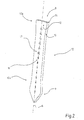
- each connecting pin 8 has an prismatic shape elongated along the axis B and comprises a first end portion 10a, provided with a tip 9, a second end portion 10b, opposite to the end portion 10a, and a narrow central portion 12 having a substantially rectangular shape and a substantially constant cross-section; the two end portions 10a and 10b are joined continuously without interruption by rounded and/or chamfered profiles to the central portion 12 and are wider laterally with respect to the axis B than the central portion 12 to make the connecting pin 8 self-anchoring; the end portions 10a and 10b diverge from the central portion 12 gradually.
- the connecting pin 8 is flattened between two substantially flat and parallel opposite faces 13, 14 defined respectively by an upper base and a lower base of the connecting pin 8; the faces 13, 14 are pointed towards the end portion 10a, remaining substantially parallel to one another, the thickness of each connecting pin 8 remaining constant along its entire length.
- the faces 13, 14 are joined by two lateral sides 15 having constant height.
- the sides 15 converge in the end portion 10a to form the tip 9.
- the thickness of the connecting pin 8 may be variable, possibly in the end portions 10a, 10b, in order to meet any particular structural requirements.
- the connecting pin 8 a particular self-anchoring characteristic, to ensure the firm anchorage of the concrete layers 2, 3.
- the use of a plurality of connecting pins 8 prevents any sliding movements of one or both of the concrete layers 2 and 3 in relation to the layer of insulating material 4 (movement in a direction parallel to the axis A), and separating movements of one of the concrete layers 2 and 3 with respect to the layer of insulating material 4 (movement along a direction orthogonal to the axis A).
- Each connecting pin 8 is provided with at least one graduated scale 16, for example a centimetre scale, arranged visibly on a surface 17 of the connecting pin 8 and extending in a direction that is substantially parallel to the axis B.
- the graduated scale 16 is arranged on the face 13 (i.e. the surface 17 is part of the face 13), but it is understood that the graduated scale 16 could instead be arranged on the opposite face 14, or on both faces 13, 14, and/or on a side 15.
- the purpose of the graduated scale 16 is to provide the level of penetration of the connecting pin 8 into the layer of insulating material 4, to enable the installer to immediately and accurately gauge the level of penetration of the connecting pin 8 into the layer of insulating material 4.
- the connecting pins 8 are made of a material with low heat conductivity, plastic for example, to guarantee adequate insulation.
- the connecting pin 8 comprises in the central portion 12, preferably near the end portion 10a, a pair of transversal teeth 22 that protrude from the connecting pin 8, for example from respective faces 13, 14 of the connecting pin 8, in a direction that is substantially transversal, and in particular substantially orthogonal, to the axis B of the connecting pin 8 in order to improve the anchorage of the connecting pin 8 inside the layer of insulating material 4.
- a first concrete casting is performed, preferably of reinforced concrete, in a formwork or containment panel (known in the prior art and not illustrated in the attached drawings) to produce the concrete layer 2; next, with the concrete layer 2 still fresh, the layer of insulating material 4 is placed on the freshly formed concrete layer 2.
- a plurality of connecting pins 8 are then inserted into the layer of insulating material 4 in a direction that is substantially orthogonal to said layer of insulating material 4 and to the axis A, so that the respective tips 9 penetrate into the prefabricated elements of the layer of insulating material 4.
- the connecting pins 8 are inserted between one prefabricated element and the other of the layer of insulating material 4, so that the connecting pins 8 do not interfere with the ventilation ducts inside the prefabricated elements.
- the connecting pins 8 are then pushed, even simply by hand, so as to pass completely through the layer of insulating material 4 so that the end portion 10a protrudes from the layer of insulating material 4 and penetrates the concrete layer 2 until it touches the formwork.
- the length of the connecting pin 8 is such that, in use, the central portion 12 passes completely through the layer of insulating material 4 and the end portions 10a and 10b respectively engage the concrete layers 2 and 3.
- the installer can easily verify whether the desired level of penetration has been achieved by using the graduated scale 16 provided on each connecting pin 8.
- the insertion of the connecting pins 8 into the layer of insulating material 4 may also be performed with the help of a template (known in the prior art and not illustrated), which facilitates the correct spacing between the connecting pins 8.
- the insulating panel 1 is ready for use.
- the present invention has the following advantages.
- the connecting pins 8 of the joining system 7 are self-anchoring thanks to their characteristic shape, which is however extremely simple and cheap to produce, and overcomes the need for the lengthy and expensive processes that are required in order to produce threaded connecting pins provided with flanges or anchoring means to prevent any movement of the concrete layers.
- the pointed shape of the connecting pin 8 facilitates its penetration into the prefabricated elements that make up the layer of insulating material 4 or between one prefabricated element and the other of the layer of insulating material 4, which generally has a relatively high degree of hardness, even if not predrilled; and the rounded and chamfered shape of the connecting pin 8 allows the connecting pin 8 to slide better inside the layer of insulating material 4 once said connecting pin 8 has penetrated (whether inserted into the individual prefabricated elements that make up the layer of insulating material 4 or inserted between one prefabricated element and the other of the layer of insulating material 4).
- the flattened shape with constant thickness of the connecting pin 8 also facilitates its insertion through the layer of insulating material 4 and in particular its insertion between one prefabricated element and the other of the layer of insulating material 4.
- the graduated scale 16 allows the operator to immediately gauge the level of penetration of the connecting pin 8 into the layer of insulating material 4. Said aspect is considerably advantageous for the user and prevents errors in the subjective evaluation of the level of penetration.
- teeth 22, if present, further improve the anchorage of the connecting pin 8 and in particular prevent the connecting pin 8 from coming out of the layer of insulating material 4 engaged by the teeth 22.
Landscapes
- Engineering & Computer Science (AREA)
- Architecture (AREA)
- Civil Engineering (AREA)
- Structural Engineering (AREA)
- Building Environments (AREA)
- Joining Of Building Structures In Genera (AREA)
Applications Claiming Priority (1)
| Application Number | Priority Date | Filing Date | Title |
|---|---|---|---|
| ITMI20060361 ITMI20060361U1 (it) | 2006-10-20 | 2006-10-20 | Sistema di collegamento per pannelli isolanti |
Publications (2)
| Publication Number | Publication Date |
|---|---|
| EP1916348A1 true EP1916348A1 (de) | 2008-04-30 |
| EP1916348B1 EP1916348B1 (de) | 2016-05-25 |
Family
ID=38982462
Family Applications (1)
| Application Number | Title | Priority Date | Filing Date |
|---|---|---|---|
| EP07118930.2A Active EP1916348B1 (de) | 2006-10-20 | 2007-10-19 | Verbindungssystem für isolierende Paneele |
Country Status (3)
| Country | Link |
|---|---|
| EP (1) | EP1916348B1 (de) |
| ES (1) | ES2588202T3 (de) |
| IT (1) | ITMI20060361U1 (de) |
Cited By (3)
| Publication number | Priority date | Publication date | Assignee | Title |
|---|---|---|---|---|
| FR2939817A1 (fr) * | 2008-12-11 | 2010-06-18 | Adrien Sarnari | Bloc elementaire prefabrique pour la construction d'un mur a isolation exterieure |
| WO2011028882A1 (en) * | 2009-09-02 | 2011-03-10 | 21St Century Structures, Llc | Embedded height adjustment mechanism for double-wall building panels |
| IT201700034762A1 (it) * | 2017-03-29 | 2018-09-29 | Anton Massimo Galluccio | Pannello di armatura per strutture di cemento armato |
Citations (7)
| Publication number | Priority date | Publication date | Assignee | Title |
|---|---|---|---|---|
| US2653469A (en) * | 1948-06-12 | 1953-09-29 | Patrick J Callan | Building wall construction |
| BE898653A (nl) * | 1984-01-11 | 1984-05-02 | Cbr Cementbedrijven Nv | Verbindingsstuk voor sandwichpaneel en aldus bekomen sandwichpaneel |
| DD245919A1 (de) * | 1986-02-10 | 1987-05-20 | Potsdam Landbauprojekt | Verbindungselement fuer baukonstruktionen |
| GB2268761A (en) * | 1992-07-14 | 1994-01-19 | Ensor Metal Products Limited | Wall tie |
| US5519973A (en) * | 1993-08-17 | 1996-05-28 | H.K. Composites, Inc. | Highly insulative connector rods and methods for their manufacture and use in highly insulated composite walls |
| EP1321681A1 (de) * | 2001-12-19 | 2003-06-25 | Werner Rüdel | Vorrichtung zum Halten eines Gegenstandes an einem Objekt sowie Verfahren zu dessen Befestigung an dem Objekt |
| GB2404385A (en) * | 2003-06-28 | 2005-02-02 | Kwok Pun Chan | Wall tie with distal mortar engaging formations |
-
2006
- 2006-10-20 IT ITMI20060361 patent/ITMI20060361U1/it unknown
-
2007
- 2007-10-19 ES ES07118930.2T patent/ES2588202T3/es active Active
- 2007-10-19 EP EP07118930.2A patent/EP1916348B1/de active Active
Patent Citations (7)
| Publication number | Priority date | Publication date | Assignee | Title |
|---|---|---|---|---|
| US2653469A (en) * | 1948-06-12 | 1953-09-29 | Patrick J Callan | Building wall construction |
| BE898653A (nl) * | 1984-01-11 | 1984-05-02 | Cbr Cementbedrijven Nv | Verbindingsstuk voor sandwichpaneel en aldus bekomen sandwichpaneel |
| DD245919A1 (de) * | 1986-02-10 | 1987-05-20 | Potsdam Landbauprojekt | Verbindungselement fuer baukonstruktionen |
| GB2268761A (en) * | 1992-07-14 | 1994-01-19 | Ensor Metal Products Limited | Wall tie |
| US5519973A (en) * | 1993-08-17 | 1996-05-28 | H.K. Composites, Inc. | Highly insulative connector rods and methods for their manufacture and use in highly insulated composite walls |
| EP1321681A1 (de) * | 2001-12-19 | 2003-06-25 | Werner Rüdel | Vorrichtung zum Halten eines Gegenstandes an einem Objekt sowie Verfahren zu dessen Befestigung an dem Objekt |
| GB2404385A (en) * | 2003-06-28 | 2005-02-02 | Kwok Pun Chan | Wall tie with distal mortar engaging formations |
Cited By (5)
| Publication number | Priority date | Publication date | Assignee | Title |
|---|---|---|---|---|
| FR2939817A1 (fr) * | 2008-12-11 | 2010-06-18 | Adrien Sarnari | Bloc elementaire prefabrique pour la construction d'un mur a isolation exterieure |
| WO2011028882A1 (en) * | 2009-09-02 | 2011-03-10 | 21St Century Structures, Llc | Embedded height adjustment mechanism for double-wall building panels |
| IT201700034762A1 (it) * | 2017-03-29 | 2018-09-29 | Anton Massimo Galluccio | Pannello di armatura per strutture di cemento armato |
| WO2018179020A1 (en) * | 2017-03-29 | 2018-10-04 | Anton Massimo Galluccio | Panel of insulating material with attached reinforcement |
| US10774531B2 (en) | 2017-03-29 | 2020-09-15 | Anton Massimo Galluccio | Panel of insulating material with attached reinforcement |
Also Published As
| Publication number | Publication date |
|---|---|
| ITMI20060361U1 (it) | 2008-04-21 |
| ES2588202T3 (es) | 2016-10-31 |
| EP1916348B1 (de) | 2016-05-25 |
Similar Documents
| Publication | Publication Date | Title |
|---|---|---|
| US3964227A (en) | Anchoring apparatus for fixedly spacing multiple wall constructions | |
| RU2658423C1 (ru) | Способ конструирования волокнистого армирующего материала ленточного типа для подпорной стены из армированного грунта | |
| US8448404B2 (en) | Bond beam rebar positioner | |
| CN103615258B (zh) | 巷道交叉点的中间岩柱的支护结构和支护方法 | |
| EP1916348B1 (de) | Verbindungssystem für isolierende Paneele | |
| US20080202052A1 (en) | Screeding Apparatus and System for a Three Dimensional Panel | |
| US6895720B2 (en) | High strength composite wall connectors having tapered or pointed ends | |
| KR101821630B1 (ko) | 전단보강 하프 피씨 슬래브 구조체 및 시공방법 | |
| KR101439314B1 (ko) | 보강토 옹벽 축조용 금속 스트립 보강재 | |
| US20110247291A1 (en) | Reinforcement Bar Support Device | |
| KR102171006B1 (ko) | 강화 콘크리트 바닥을 구축하기 위한 소결 발포 폴리스티렌 모듈형 요소 | |
| US2432622A (en) | Structural member | |
| US8713887B2 (en) | System for reinforcing a building structural component | |
| KR20120090502A (ko) | 3방향 구속타입 전면판을 갖는 쏘일네일 장치 | |
| JP5901008B2 (ja) | 壁板接合構造 | |
| US4594830A (en) | Bonding unit for reinforced concrete structural components | |
| CN211948516U (zh) | 预制件及具有其的咬合桩 | |
| DE60011415T2 (de) | Konstruktionselement für gebäude und versteifungsplatte für ein solches element | |
| CN105648870B (zh) | 试车场搓板路的施工方法 | |
| RU2640527C2 (ru) | Способ сооружения стеновой конструкции | |
| KR101357005B1 (ko) | 배관 구조가 개선된 슬래브 데크 시스템 | |
| CA2861147C (en) | Reversible, thermo-acoustic panel for reversible, variable-geometry formwork | |
| US8015768B2 (en) | Insulation panel | |
| CN207392485U (zh) | 一种用于连接混凝土层的保温板组件和建筑物 | |
| RU2313639C1 (ru) | Многопустотное строительное изделие и способ его изготовления |
Legal Events
| Date | Code | Title | Description |
|---|---|---|---|
| PUAI | Public reference made under article 153(3) epc to a published international application that has entered the european phase |
Free format text: ORIGINAL CODE: 0009012 |
|
| AK | Designated contracting states |
Kind code of ref document: A1 Designated state(s): AT BE BG CH CY CZ DE DK EE ES FI FR GB GR HU IE IS IT LI LT LU LV MC MT NL PL PT RO SE SI SK TR |
|
| AX | Request for extension of the european patent |
Extension state: AL BA HR MK RS |
|
| 17P | Request for examination filed |
Effective date: 20081030 |
|
| AKX | Designation fees paid |
Designated state(s): DE ES GB RO SE |
|
| 17Q | First examination report despatched |
Effective date: 20101230 |
|
| GRAP | Despatch of communication of intention to grant a patent |
Free format text: ORIGINAL CODE: EPIDOSNIGR1 |
|
| INTG | Intention to grant announced |
Effective date: 20151211 |
|
| GRAS | Grant fee paid |
Free format text: ORIGINAL CODE: EPIDOSNIGR3 |
|
| GRAA | (expected) grant |
Free format text: ORIGINAL CODE: 0009210 |
|
| AK | Designated contracting states |
Kind code of ref document: B1 Designated state(s): DE ES GB RO SE |
|
| REG | Reference to a national code |
Ref country code: GB Ref legal event code: FG4D |
|
| REG | Reference to a national code |
Ref country code: DE Ref legal event code: R096 Ref document number: 602007046415 Country of ref document: DE |
|
| REG | Reference to a national code |
Ref country code: RO Ref legal event code: EPE |
|
| REG | Reference to a national code |
Ref country code: SE Ref legal event code: TRGR |
|
| REG | Reference to a national code |
Ref country code: ES Ref legal event code: FG2A Ref document number: 2588202 Country of ref document: ES Kind code of ref document: T3 Effective date: 20161031 |
|
| REG | Reference to a national code |
Ref country code: DE Ref legal event code: R097 Ref document number: 602007046415 Country of ref document: DE |
|
| PLBE | No opposition filed within time limit |
Free format text: ORIGINAL CODE: 0009261 |
|
| STAA | Information on the status of an ep patent application or granted ep patent |
Free format text: STATUS: NO OPPOSITION FILED WITHIN TIME LIMIT |
|
| 26N | No opposition filed |
Effective date: 20170228 |
|
| P01 | Opt-out of the competence of the unified patent court (upc) registered |
Effective date: 20230515 |
|
| PGFP | Annual fee paid to national office [announced via postgrant information from national office to epo] |
Ref country code: DE Payment date: 20251029 Year of fee payment: 19 |
|
| PGFP | Annual fee paid to national office [announced via postgrant information from national office to epo] |
Ref country code: GB Payment date: 20251027 Year of fee payment: 19 |
|
| PGFP | Annual fee paid to national office [announced via postgrant information from national office to epo] |
Ref country code: SE Payment date: 20251027 Year of fee payment: 19 |
|
| PGFP | Annual fee paid to national office [announced via postgrant information from national office to epo] |
Ref country code: RO Payment date: 20251006 Year of fee payment: 19 |
|
| PGFP | Annual fee paid to national office [announced via postgrant information from national office to epo] |
Ref country code: ES Payment date: 20251103 Year of fee payment: 19 |