EP1916427A2 - Vérin - Google Patents
Vérin Download PDFInfo
- Publication number
- EP1916427A2 EP1916427A2 EP07020934A EP07020934A EP1916427A2 EP 1916427 A2 EP1916427 A2 EP 1916427A2 EP 07020934 A EP07020934 A EP 07020934A EP 07020934 A EP07020934 A EP 07020934A EP 1916427 A2 EP1916427 A2 EP 1916427A2
- Authority
- EP
- European Patent Office
- Prior art keywords
- actuator
- actuating cylinder
- hydraulic
- actuator according
- actuators
- Prior art date
- Legal status (The legal status is an assumption and is not a legal conclusion. Google has not performed a legal analysis and makes no representation as to the accuracy of the status listed.)
- Withdrawn
Links
Images




Classifications
-
- F—MECHANICAL ENGINEERING; LIGHTING; HEATING; WEAPONS; BLASTING
- F15—FLUID-PRESSURE ACTUATORS; HYDRAULICS OR PNEUMATICS IN GENERAL
- F15B—SYSTEMS ACTING BY MEANS OF FLUIDS IN GENERAL; FLUID-PRESSURE ACTUATORS, e.g. SERVOMOTORS; DETAILS OF FLUID-PRESSURE SYSTEMS, NOT OTHERWISE PROVIDED FOR
- F15B15/00—Fluid-actuated devices for displacing a member from one position to another; Gearing associated therewith
- F15B15/18—Combined units comprising both motor and pump
-
- G—PHYSICS
- G09—EDUCATION; CRYPTOGRAPHY; DISPLAY; ADVERTISING; SEALS
- G09B—EDUCATIONAL OR DEMONSTRATION APPLIANCES; APPLIANCES FOR TEACHING, OR COMMUNICATING WITH, THE BLIND, DEAF OR MUTE; MODELS; PLANETARIA; GLOBES; MAPS; DIAGRAMS
- G09B9/00—Simulators for teaching or training purposes
- G09B9/02—Simulators for teaching or training purposes for teaching control of vehicles or other craft
- G09B9/08—Simulators for teaching or training purposes for teaching control of vehicles or other craft for teaching control of aircraft, e.g. Link trainer
- G09B9/12—Motion systems for aircraft simulators
- G09B9/14—Motion systems for aircraft simulators controlled by fluid actuated piston or cylinder ram
Definitions
- the present invention relates to an actuator, in particular for use in flight simulators, with a hydraulic actuating cylinder and a proportional or servo valve for controlling the hydraulic actuating cylinder. Furthermore, the present invention relates to a flight simulator with at least one such actuator.
- Such actuators with a hydraulic actuator cylinder are used to move the cab of a flight simulator and thus to enable a realistic simulation of the flight movement.
- actuating cylinders are used, which are supplied with pressure by a central hydraulic unit. Due to the long supply lines such actuators but lose momentum, especially due to the large hydraulic fluid volumes of the hydraulic lines. Even otherwise, the known actuators are not very dynamic, especially since the actuating cylinder for moving the cab of the flight simulator only the static load, which weighs on you by the weight of the cab overcome and in addition the piston rods of the actuating cylinders are not easy enough. Even otherwise, the known systems are expensive, difficult to maintain and consume a lot of space and energy. In particular, the large volumes of hydraulic fluid through the supply lines from the central hydraulic unit increase the cost of operation, and the maintenance and change of the individual actuators are moreover complicated by the necessary discharge of the hydraulic fluid.
- the object of the present invention is therefore to provide an actuator, in particular for use in flight simulators, which has high dynamics. Furthermore, it is an object of the present invention to provide an actuator available, which can be produced and operated inexpensively and is easy to service. It is also an object of the present invention to provide a corresponding flight simulator available.
- an actuator in particular for use in flight simulators, comprises a hydraulic actuating cylinder and a proportional or servo valve for controlling the hydraulic actuating cylinder, wherein a motor pump unit for pressure generation is arranged on the actuating cylinder.
- This increases the dynamics of the actuator, as it can be dispensed with long supply lines.
- the amount of hydraulic fluid required to operate the actuator can be massively reduced.
- When operating multiple actuators so can be dispensed with a central hydraulic pressure source and external hydraulic lines. This in turn allows a high level of dynamics as well as cost and space savings, since no extra space for a large hydraulic unit must be made available.
- the maintenance of the system is particularly easy because the entire actuator can be completely removed without separating the actuator cylinder from the motor pump unit. So it must be separated to remove the actuator only electrical lines.
- the motor pump unit mounted on the housing of the actuator cylinder, either directly or via fasteners, and moves with the actuator cylinder housing.
- the motor pump unit consists advantageously of an induction motor with constant rotational speed and further advantageously of a pump with adjustable flow rate, advantageously an axial piston pump with adjustable stroke.
- the engine is advantageously equipped with a fan to cool both the engine and the hydraulic accumulator.
- the engine is further advantageously mounted via an insulating element on the actuating cylinder to reduce the transmission of vibration and noise from the engine to the actuating cylinder.
- the pump is advantageously arranged inside a hydraulic accumulator in order to reduce the risk of leakage.
- the pump advantageously has an integrated hydraulic control for setting a constant output pressure.
- the pump is operated at a quarter of its maximum power to guarantee a long life.
- the proportional or servo valve is arranged on the actuating cylinder.
- the arrangement of the valve on the actuating cylinder long hydraulic lines between the valve and actuating cylinder are avoided, so that the actuator according to the invention has extremely short response times and high dynamics.
- a proportional valve is used since it reacts less sensitively to impurities in the hydraulic fluid than a servo valve. It is obvious to a person skilled in the art that the use of such a proportional valve is of great advantage even without the arrangement on the actuating cylinder, but in combination there is a particularly good dynamics and controllability.
- the proportional valve includes an integrated feedback on the valve position and advantageously an integrated electronics. The feedback signal indicating the position of the valve can be used to detect and avoid malfunction.
- the integrated electronics allow a precise and highly dynamic control and make it possible to use different input signals for control. advantageously, If the proportional valve is constructed in two stages, the first stage is controlled directly.
- the present invention further comprises an actuator in which the piston rod of the actuating cylinder is guided for friction reduction by means of a linear bearing.
- a linear bearing which is advantageously arranged in the tip of the actuating cylinder housing.
- the tip of the actuating cylinder housing is advantageously a separate element which is installed from the front in the rest of the actuating cylinder housing.
- the present invention advantageously comprises low-friction guide rings and / or seals for the piston rod. Overall, such a very low-friction bearing of the piston rod and thus a highly dynamic movement of the actuator can be achieved. It is obvious to a person skilled in the art that the use of a linear bearing for guiding the piston rod of the actuating cylinder is of great advantage, independently of the other construction of the actuator.
- the present invention furthermore comprises an actuating drive, in which a gas spring, in particular for compensating at least part of the static load bearing on the actuating cylinder, is integrated in the actuating cylinder.
- a gas spring in particular for compensating at least part of the static load bearing on the actuating cylinder, is integrated in the actuating cylinder.
- the gas spring is filled with nitrogen.
- the gas spring is integrated in the piston rod of the adjusting cylinder, so that here a very compact construction can be selected.
- the gas spring further comprises a pressure sensor to monitor the gas pressure in the gas spring can. It is obvious to those skilled in the art that the use of a gas spring in the actuating cylinder is also of great advantage, regardless of the other construction of the actuator.
- the gas spring comprises a position sensor for determining the position of the actuating cylinder piston. This allows a very compact design and also facilitates the replacement or repair of the sensor, since the hydraulic fluid must not be omitted for this purpose.
- the arrangement of the position sensor in the gas spring allows a particularly low-wear design.
- a hydraulic accumulator for reducing the required peak power of the motor pump unit is provided.
- Power peaks can be cushioned so over the advantageously designed as a high-pressure hydraulic accumulator hydraulic accumulator, so that the motor pump unit must be designed less strong. This saves weight, space and costs.
- the hydraulic accumulator is also used to actively enter or exit the actuator in the event of a fault. This increases the safety of the actuator, so that not a second parallel system for extending or retracting the actuator is required. Even so, costs can be saved.
- the hydraulic accumulator is arranged on the actuating cylinder.
- the entire hydraulic system is arranged on the actuating cylinder. This means you can completely dispense with external hydraulic lines, which considerably reduces the amount of oil to be used and thus minimizes maintenance costs. Furthermore, the compact arrangement of the hydraulic system on the actuating cylinder allows particularly short reaction times and high dynamics of the actuator. Also, the installation or the change of an actuator is possible without any problems, since only electrical connections must be made.
- the actuating cylinder of the actuator according to the invention in particular in the Hubend Scheme to a damping.
- This allows a particularly safe and low-wear operation of the actuator according to the invention, wherein the damping force acts advantageously only in Hubend Scheme and there rises continuously.
- check valves are provided to prevent cavitations in the hydraulic fluid.
- a valve for emergency retraction is provided in the actuator according to the invention, which is preferably mounted parallel to the proportional or servo valve, in particular to reduce hydraulic losses and to reduce the size of the valve.
- the emergency retraction valve can bring the actuating cylinder into a safe position.
- the corresponding pressure chamber of the actuating cylinder with pressure, in particular from the pressure accumulator.
- the emergency retraction valve is advantageously a two-position piston valve.
- the oil filtration via the leakage oil flow of the pump wherein preferably no filter between the pump and proportional or servo valve is mounted.
- This in turn allows a particularly high dynamics of the actuator.
- the high dynamic results essentially from the fact that no pressure losses occur between the proportional or servo valve and the pump.
- a low-pressure filter can be used, which saves costs.
- the flow through the filter is almost constant, which increases the effectiveness of the filtration and makes it possible to install only a small filter.
- the valve block of the actuator continues to be an integral part of the actuating cylinder housing. This means a particularly compact arrangement of the valves, wherein the paths between the actuating cylinder and valves are minimized and no hoses must be used.
- an electrically operated motor pump unit is provided in the erfindunzien actuator, which is connected directly to an aggregate for providing the electrical power, in particular a transformer is, wherein the actuation of the actuator via the proportional or servo valve is done.
- the actuators can be completely dispensed with an expensive high-performance electronics for controlling the motors as they are operated at a constant speed.
- the actuating cylinder of the actuator according to the invention comprises two seals, in particular a low-pressure and a high-pressure seal, wherein a leak oil line is provided between the seals.
- This arrangement in turn allows a particularly low-friction bearing of the piston of the actuating cylinder.
- the present invention further comprises a flight simulator with at least one and in particular with several, in particular with six actuators according to one of the preceding claims.
- a flight simulator has an extremely high dynamic, is inexpensive and easy to maintain and has only a small footprint and low energy consumption.
- a motor pump unit for generating pressure is arranged on the actuating cylinders of the actuators.
- the motor pump units thus provide the necessary actuating cylinders with the necessary pressure so that a central pressure supply can be dispensed with. This allows easy maintenance, since the individual actuators can be easily removed, since only electrical cables must be used to connect the individual actuators.
- a central unit for providing the power for the motors of all engine pump units is provided in the flight simulator according to the invention.
- the advantageously designed as a transformer central Aggregate thus enables a central power supply of all engines.
- the motors of the motor pump units of the actuators are advantageously connected directly to this central unit, so that expensive high-performance electronics can be dispensed with.
- the actuation of the actuators then takes place via the control of the proportional or servo valves, which in turn take over the control of the actuating cylinder.
- the central unit can be operated with different voltages, which increases the flexibility of the flight simulator.
- the central unit advantageously has a central safety switch in order to switch off the power supply in the event of a fault centrally and thus guarantee a safe retraction of all actuators.
- the flight simulator comprises a control, regulation and / or monitoring electronics for the actuators.
- This electronics can advantageously be connected directly to the simulation computer, which controls the flight simulator, and thus allows central control, regulation and / or monitoring of the actuators.
- Figures 1 to 4 show an embodiment of the actuator according to the invention.
- This comprises a hydraulic actuating cylinder 10 with a cylinder housing 12 and a cylinder rod 11 displaceable therein.
- the cylinder housing 12 and piston rod 11 each have articulation points 8 and 9.
- the piston rod 11 can be moved out of the cylinder housing 12 by pressurizing the rear pressure chamber 13 is and the front pressure chamber 17 is at return pressure.
- the piston rod 11 can be retracted into the cylinder housing 12 by the front pressure chamber 17 is pressurized and the rear pressure chamber 13 is at return pressure.
- damper 19 are arranged, which dampen the movement of the piston rod 11 in the Hubendpositionen.
- a gas spring 50 is arranged inside the piston 11.
- a position sensor 55 is mounted in the interior of the gas spring 50.
- a pressure sensor 51 for measuring the gas pressure in the gas spring.
- the piston rod 11 is mounted in a friction-free manner in the cylinder housing 12 via a linear bearing 14.
- seals 15 and 16 are provided.
- a motor pump unit of a motor 40 and a pump 30 is arranged on the actuating cylinder 10.
- the motor 40 is a constant-speed induction motor which drives the variable displacement pump 30.
- the pump 30 provides via a check valve 21 pressure, which is applied to the input of a proportional valve 20. This aspect of the invention will be described in more detail with reference to FIG. 5.
- the proportional valve 20 is a two-stage highly dynamic valve, in which the first stage is controlled directly and which comprises an integrated sensor for emitting a feedback signal via the valve position. Likewise, the corresponding electronics are integrated in the proportional valve. Such a valve has the advantage that only little energy is consumed (leakage oil flow). A proportional valve is also less susceptible to contamination of the hydraulic oil than a servo valve. The integrated electronics allow a precise and dynamic regulation of the valve, whereby different input signals can be used. The feedback signal of the valve position makes it possible to detect errors and react quickly to them. The arrangement of the entire hydraulic system on the actuating cylinder 10 makes it possible to achieve an extremely compact design without any external hydraulic connections or hydraulic lines. In addition, in particular allows only minimal hydraulic oil volume between the proportional valve and the hydraulic chambers 13 and 17, a very fast response. In addition, the number of static seals can be reduced to a minimum.
- valve block 23 is an integral part of the cylinder housing of the actuating cylinder 10.
- the proportional valve 20 is externally attached to the valve block 23, so that the proportional valve 20 is not disposed within the oil-carrying area and so that it is easily accessible.
- a high pressure accumulator 35 is provided, which is also pressurized by the pump and is in communication with the input of the proportional valve.
- a pressure sensor 36 is further arranged.
- the high-pressure accumulator 35 is a correspondingly adapted high-pressure accumulator, which is also arranged on the actuating cylinder 10. As can be seen from the drawings, it is mounted directly on the cylinder housing 12 and is located on the opposite side of the motor pump unit. By using the high-pressure accumulator 35, the required peak power of the motor pump unit can be reduced. It can also be used to actively retract the actuator in the event of a fault. For this purpose, the high-pressure accumulator is connected to the hydraulic chamber 17 in the event of a fault.
- a Noteinfahrventil 22 is provided, via which the rear pressure chamber 13 can be switched to return pressure in a malfunction and the front pressure chamber 17 is pressurized, so that the piston rod 11 is retracted.
- the emergency retraction valve 22 and the proportional valve 20 are arranged in parallel to reduce the hydraulic losses and the size of the valves.
- the emergency retraction valve 22 is designed as a simple two-position valve. If necessary, the high-pressure accumulator 35 can also be isolated as an alternative to the procedure described above in the event of a fault, which further increases safety.
- the oil filtration takes place in the actuator according to the invention via a filter 25 in the leakage oil flow of the pump, so that no filter between the pump 30 and the proportional valve 20 must be arranged.
- a filter 25 in the leakage oil flow of the pump, so that no filter between the pump 30 and the proportional valve 20 must be arranged.
- a low-pressure filter must be used, wherein it is additionally ensured that the flow through the filter is approximately constant.
- only a small filter must be used.
- a standard filter can be used with the filter installed so that it is easy to change with a minimum of oil loss.
- a leakage oil line 33 is provided on the cylinder housing, which is arranged between the seals 15 and 16.
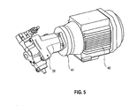
- FIG. 5 now shows the motor pump unit of the actuator according to the invention.
- the motor 40 is an electric motor, a robust induction motor with a constant Speed. If several actuators side by side z. B. used in an aircraft simulator, the individual actuators are started in succession with a time interval of 2 seconds to reduce the power peaks in the system.
- the housing of the engine is made of aluminum.
- the engine is also equipped with a quiet fan to cool both the engine and the hydraulic accumulator.
- the electric motor according to the invention has heat protection switches on each turn.
- the motor is flanged to the housing of the actuator via a special insulating flange 41 to reduce noise and minimize the transmission of vibration to the actuator.
- the pump 30 is designed to be adjustable and thus provides a constant system pressure. It is an axial piston pump with adjustable stroke. This is arranged within the hydraulic oil reservoir, so that leaks are excluded to the outside.
- the pump has an integrated hydraulic control to provide a constant pressure. The pump is only operated at about 1 ⁇ 4 of its maximum power to minimize wear and thus guarantee a long life of the pump.
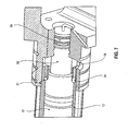
- FIG. 6a now shows the front region of the hydraulic cylinder 10 in detail.
- the nitrogen spring 50 can be seen well, which is arranged in the interior of the piston 11.
- the piston 11 is mounted with low friction via linear ball bearings 14 in the hydraulic cylinder 12.
- two seals 15 and 16 are provided, which are designed extremely low friction and between which a leakage oil line 33 is located.
- a scraper 7 is provided.
- the seals 15 and 16 are arranged behind the linear ball bearing 14, so that the linear ball bearing 14 is still in the region of the pressure chamber 17.
- the linear ball bearing is shown again in detail in FIG. 6b.
- Figure 7 now shows the structure of the rear part of the cylinder housing in a partial sectional view.
- the piston 11 is slidably mounted.
- the nitrogen spring 50 is arranged.
- a sensor 51 is provided for measuring the pressure in the nitrogen spring 50.
- the gas spring 50 has a filling valve for easy supply of nitrogen at the rear end of the cylinder housing.
- the nitrogen spring 50 is used in the actuator according to the invention to compensate for at least a portion of the load on the actuator static load. This increases the dynamics of the actuator, which thereby has to move a lower load hydraulically.
- the position sensor 55 is now arranged, which allows an extremely compact design.
- the hydraulic oil need not be drained to replace the sensor 55.
- the sensor 55 includes integrated electronics. The arrangement of the sensor within the nitrogen spring 50, this is also extremely low-wear and easily accessible.
- the hydraulic system further includes a flow restrictor 31 and check valves 24 to prevent cavitation.
- 11 damper 19 are arranged on the cylinder rod, which dampen the movements of the piston rod 11 in the Hubendpositionen. The damping in the area of the stroke end position gently increases, so that an effective damping is achieved.
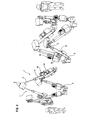
- FIG. 8 now shows the aircraft simulator according to the invention, in which the actuators according to the invention are used.
- six actuators are provided.
- a central transformer 80 is provided, which supplies the induction motors of the actuators directly via supply lines 81 and 82.
- the transformer is equipped so that it can be powered by different input voltages. It also has a safety switch that disconnects the transformer from the power source can be so that automatically all induction motors are de-energized and so a safe emergency retraction of the actuators is initiated. If necessary, the transformer includes power factor correction elements.
- the aircraft simulator further comprises the control electronics for the proportional valves.
- the task of the control electronics 61 and 62 is to convert the signals of the simulator controller into a signal for controlling the proportional valves of the actuators.
- the control electronics thus control the proportional valves and hereby the position of the actuators.
- the proportional valves of the actuators, z. As the actuators 1 and 2, are via control lines, z. B. lines 71 and 72 with their respective control electronics, z. B. 61 and 62 connected.
- the simulator control 60 has two industrial computers, a screen and a keyboard and a mouse.
- the simulator control 60 includes an emergency control.
- the drive controller 60 communicates via data lines 90 with the remainder of the flight simulator electronics.
- the system also monitors all non-critical functions, such as It can also perform automatic test procedures.
- the six actuators are connected in pairs in a V-shaped manner.
- the actuating cylinders are connected via their articulation points below with corresponding articulation points on the ground and above with the driver's cab.
- the induction motors are then directly connected to the transformer, while the proportional valves are connected to the control electronics.
Landscapes
- Engineering & Computer Science (AREA)
- Physics & Mathematics (AREA)
- Theoretical Computer Science (AREA)
- Mechanical Engineering (AREA)
- General Engineering & Computer Science (AREA)
- Aviation & Aerospace Engineering (AREA)
- Fluid Mechanics (AREA)
- Business, Economics & Management (AREA)
- Educational Administration (AREA)
- Educational Technology (AREA)
- General Physics & Mathematics (AREA)
- Fluid-Pressure Circuits (AREA)
- Actuator (AREA)
Applications Claiming Priority (1)
| Application Number | Priority Date | Filing Date | Title |
|---|---|---|---|
| DE200620016451 DE202006016451U1 (de) | 2006-10-26 | 2006-10-26 | Stellantrieb |
Publications (2)
| Publication Number | Publication Date |
|---|---|
| EP1916427A2 true EP1916427A2 (fr) | 2008-04-30 |
| EP1916427A3 EP1916427A3 (fr) | 2012-05-23 |
Family
ID=38984154
Family Applications (1)
| Application Number | Title | Priority Date | Filing Date |
|---|---|---|---|
| EP07020934A Withdrawn EP1916427A3 (fr) | 2006-10-26 | 2007-10-25 | Vérin |
Country Status (2)
| Country | Link |
|---|---|
| EP (1) | EP1916427A3 (fr) |
| DE (1) | DE202006016451U1 (fr) |
Cited By (5)
| Publication number | Priority date | Publication date | Assignee | Title |
|---|---|---|---|---|
| CN103233932A (zh) * | 2013-04-19 | 2013-08-07 | 燕山大学 | 一种高集成性液压驱动单元结构 |
| CN103727094A (zh) * | 2014-01-26 | 2014-04-16 | 重庆市巴山液压附件厂有限公司 | 一种电液伺服数控推杆装置 |
| EP2808562A1 (fr) * | 2012-12-11 | 2014-12-03 | Pro Motion, LLC | Servo-mécanisme à alimentation de fluide autonome |
| CN109026860A (zh) * | 2018-08-06 | 2018-12-18 | 中国矿业大学 | 比例伺服阀控液压支护平台立柱油缸系统及压力控制方法 |
| CN114001066A (zh) * | 2021-10-29 | 2022-02-01 | 昆山北极光电子科技有限公司 | 一种封闭式液压直线驱动器 |
Families Citing this family (7)
| Publication number | Priority date | Publication date | Assignee | Title |
|---|---|---|---|---|
| DE102008027474B4 (de) * | 2008-06-09 | 2022-12-15 | Liebherr-Aerospace Lindenberg Gmbh | Stellglied sowie Drehgestellsteuerung |
| DE202010004921U1 (de) * | 2010-04-13 | 2011-09-01 | Faun Umwelttechnik Gmbh & Co. Kg | Elektrozylinder |
| DE102012202100B4 (de) * | 2012-02-13 | 2024-03-28 | Zf Friedrichshafen Ag | Hydraulischer Aktuator |
| DE202014001498U1 (de) | 2014-02-21 | 2015-05-22 | Eckhard Polman | Stellantrieb mit Kurvensteuerung |
| DE102015209644A1 (de) * | 2015-05-27 | 2016-12-01 | Robert Bosch Gmbh | Hydrostatischer linearer Aktuator und Anordnung mit hydrostatischen linearen Aktuatoren |
| DE102019216083B4 (de) | 2019-10-18 | 2024-11-21 | Hawe Hydraulik Se | Fahrgast-Rückhaltevorrichtung und Fahrgeschäft-Fahrgasteinheit |
| CN115306859B (zh) * | 2022-10-11 | 2022-12-16 | 南通市通州区华凯机械有限公司 | 一种减震装置 |
Family Cites Families (10)
| Publication number | Priority date | Publication date | Assignee | Title |
|---|---|---|---|---|
| FR2229879A1 (en) * | 1973-05-15 | 1974-12-13 | Agiman Jacques | Electrically controlled double acting hydraulic ram - has oil-hydraulic accumulator charged when at rest |
| US4630441A (en) * | 1984-09-04 | 1986-12-23 | The Boeing Company | Electrohydraulic actuator for aircraft control surfaces |
| DE3607419C1 (en) * | 1986-03-06 | 1987-01-15 | Detlef Koeppen | Pressure-medium-operated cylinder/pump unit |
| US5595103A (en) * | 1993-03-18 | 1997-01-21 | Ecoff; William B. | Hydraulic drive assembly for electrical discharge machine |
| DE19523764A1 (de) * | 1995-06-29 | 1997-01-02 | Schlattl Werner Bavaria Tech | Pneumatische Kolben-Zylinder-Einheit |
| DE19901570C2 (de) * | 1999-01-16 | 2000-08-03 | Johannes Kotschner | Bewegungsvorrichtung für einen Fahr- oder Flugsimulator |
| ITTO20010915A1 (it) * | 2001-09-25 | 2003-03-25 | Vep Automation Srl | Dispositivo di controllo dell'oscillazione del braccio di un'attrezzatura di movimentazione del tipo a leva oscillabile. |
| AT412114B (de) * | 2002-09-25 | 2004-09-27 | Hoerbiger Hydraulik | Doppeltwirkender arbeitszylinder |
| JP3947098B2 (ja) * | 2002-12-04 | 2007-07-18 | 和興フィルタテクノロジー株式会社 | 作動油濾過装置 |
| DE10306006B4 (de) * | 2003-02-12 | 2005-02-24 | Knapp, Jürgen Michael | Hydraulikmodul |
-
2006
- 2006-10-26 DE DE200620016451 patent/DE202006016451U1/de not_active Expired - Lifetime
-
2007
- 2007-10-25 EP EP07020934A patent/EP1916427A3/fr not_active Withdrawn
Cited By (6)
| Publication number | Priority date | Publication date | Assignee | Title |
|---|---|---|---|---|
| EP2808562A1 (fr) * | 2012-12-11 | 2014-12-03 | Pro Motion, LLC | Servo-mécanisme à alimentation de fluide autonome |
| CN103233932A (zh) * | 2013-04-19 | 2013-08-07 | 燕山大学 | 一种高集成性液压驱动单元结构 |
| CN103233932B (zh) * | 2013-04-19 | 2015-04-29 | 燕山大学 | 一种高集成性液压驱动单元结构 |
| CN103727094A (zh) * | 2014-01-26 | 2014-04-16 | 重庆市巴山液压附件厂有限公司 | 一种电液伺服数控推杆装置 |
| CN109026860A (zh) * | 2018-08-06 | 2018-12-18 | 中国矿业大学 | 比例伺服阀控液压支护平台立柱油缸系统及压力控制方法 |
| CN114001066A (zh) * | 2021-10-29 | 2022-02-01 | 昆山北极光电子科技有限公司 | 一种封闭式液压直线驱动器 |
Also Published As
| Publication number | Publication date |
|---|---|
| EP1916427A3 (fr) | 2012-05-23 |
| DE202006016451U1 (de) | 2008-03-06 |
Similar Documents
| Publication | Publication Date | Title |
|---|---|---|
| EP1916427A2 (fr) | Vérin | |
| EP2039582B1 (fr) | Amortisseur hydraulique actif et mécanisme de commande hydraulique | |
| DE112012000961B4 (de) | Hydraulische Einrichtung zur Betätigung einer Kupplung | |
| DE102008027474B4 (de) | Stellglied sowie Drehgestellsteuerung | |
| EP2923089B1 (fr) | Dispositif de commande de vanne de turbine | |
| DE602005000198T2 (de) | Aufhängevorrichtung eines Flugzeugtriebwerks an einem Flügelpylon | |
| DE69109420T2 (de) | Hydrostatische Betätigungsvorrichtung, insbesondere als Sicherheitsvorrichtung und ein Flugsteuersystem, das eine solche Betätigungsvorrichtung enthält. | |
| EP2181221A1 (fr) | Commande hydraulique d'excavatrice, notamment pour un mécanisme rotatif | |
| EP1588057A1 (fr) | Systeme hydraulique pour entrainements lineaires commandes par des elements deplaceurs | |
| DE102010002091A1 (de) | Bremssteuersystem | |
| EP3003807B2 (fr) | Releveur de frein électrohydraulique et ensemble de freinage | |
| DE2333525B2 (de) | Hydraulische Leitschaufel-Verstelleinrichtung | |
| DE102010007152A1 (de) | Fluidbetätigter Stellantrieb an einer Armatur | |
| DE102016102387A1 (de) | Hydraulischer Antrieb zum Ausführen einer linearen Bewegung | |
| DE102015213540A1 (de) | Hocheffizientes hydraulisches verteilergetriebe | |
| DE19916366A1 (de) | Aktuator | |
| DE102011105923A1 (de) | Hydraulisches Antriebsystem mit mehreren Hydraulikpumpen und einer Energierückgewinnung | |
| WO2014191394A2 (fr) | Unité fonctionnelle et releveur de frein électrohydraulique équipé d'une telle unité | |
| DE19654781A1 (de) | Hilfseinrichtung zur Realisierung einer Redundanz für die Energieversorgung von Flugsteuerungsantrieben | |
| DE4327651C2 (de) | Steuermodul für eine verstellbare Hydromaschine und Verwendung eines derartigen Steuermoduls für einen hydrostatischen Fahrantrieb | |
| EP2529821B1 (fr) | Système d'entraînement hydraulique pour une scène de théâtre avec une pompe hydraulique à réglage de vitesse comme élément de commande | |
| DE102010012635A1 (de) | Achseinheit | |
| EP4442475A1 (fr) | Système modulaire hydraulique | |
| EP0415046B1 (fr) | Dispositif d'entraînement hydraulique | |
| WO2014016002A1 (fr) | Unité d'actionnement d'un système de freinage et procédé de freinage |
Legal Events
| Date | Code | Title | Description |
|---|---|---|---|
| PUAI | Public reference made under article 153(3) epc to a published international application that has entered the european phase |
Free format text: ORIGINAL CODE: 0009012 |
|
| AK | Designated contracting states |
Kind code of ref document: A2 Designated state(s): AT BE BG CH CY CZ DE DK EE ES FI FR GB GR HU IE IS IT LI LT LU LV MC MT NL PL PT RO SE SI SK TR |
|
| AX | Request for extension of the european patent |
Extension state: AL BA HR MK RS |
|
| RIC1 | Information provided on ipc code assigned before grant |
Ipc: G09B 9/14 20060101ALI20120207BHEP Ipc: F15B 15/18 20060101AFI20120207BHEP |
|
| PUAL | Search report despatched |
Free format text: ORIGINAL CODE: 0009013 |
|
| AK | Designated contracting states |
Kind code of ref document: A3 Designated state(s): AT BE BG CH CY CZ DE DK EE ES FI FR GB GR HU IE IS IT LI LT LU LV MC MT NL PL PT RO SE SI SK TR |
|
| AX | Request for extension of the european patent |
Extension state: AL BA HR MK RS |
|
| RIC1 | Information provided on ipc code assigned before grant |
Ipc: G09B 9/14 20060101ALI20120417BHEP Ipc: F15B 15/18 20060101AFI20120417BHEP |
|
| AKY | No designation fees paid | ||
| REG | Reference to a national code |
Ref country code: DE Ref legal event code: R108 |
|
| REG | Reference to a national code |
Ref country code: DE Ref legal event code: R108 Effective date: 20130130 |
|
| STAA | Information on the status of an ep patent application or granted ep patent |
Free format text: STATUS: THE APPLICATION IS DEEMED TO BE WITHDRAWN |
|
| 18D | Application deemed to be withdrawn |
Effective date: 20121124 |