EP1916498B1 - Procédé de mesure et/ou de correction de la forme d'une pièce à usiner selon la déformation par pliage et presse plieuse destinée à exécuter le procédé - Google Patents
Procédé de mesure et/ou de correction de la forme d'une pièce à usiner selon la déformation par pliage et presse plieuse destinée à exécuter le procédé Download PDFInfo
- Publication number
- EP1916498B1 EP1916498B1 EP07020863A EP07020863A EP1916498B1 EP 1916498 B1 EP1916498 B1 EP 1916498B1 EP 07020863 A EP07020863 A EP 07020863A EP 07020863 A EP07020863 A EP 07020863A EP 1916498 B1 EP1916498 B1 EP 1916498B1
- Authority
- EP
- European Patent Office
- Prior art keywords
- bending
- work piece
- section
- measuring
- cheek
- Prior art date
- Legal status (The legal status is an assumption and is not a legal conclusion. Google has not performed a legal analysis and makes no representation as to the accuracy of the status listed.)
- Not-in-force
Links
Images



Classifications
-
- G—PHYSICS
- G01—MEASURING; TESTING
- G01B—MEASURING LENGTH, THICKNESS OR SIMILAR LINEAR DIMENSIONS; MEASURING ANGLES; MEASURING AREAS; MEASURING IRREGULARITIES OF SURFACES OR CONTOURS
- G01B7/00—Measuring arrangements characterised by the use of electric or magnetic techniques
- G01B7/30—Measuring arrangements characterised by the use of electric or magnetic techniques for measuring angles or tapers; for testing the alignment of axes
-
- B—PERFORMING OPERATIONS; TRANSPORTING
- B21—MECHANICAL METAL-WORKING WITHOUT ESSENTIALLY REMOVING MATERIAL; PUNCHING METAL
- B21D—WORKING OR PROCESSING OF SHEET METAL OR METAL TUBES, RODS OR PROFILES WITHOUT ESSENTIALLY REMOVING MATERIAL; PUNCHING METAL
- B21D5/00—Bending sheet metal along straight lines, e.g. to form simple curves
- B21D5/04—Bending sheet metal along straight lines, e.g. to form simple curves on brakes making use of clamping means on one side of the work
-
- B—PERFORMING OPERATIONS; TRANSPORTING
- B21—MECHANICAL METAL-WORKING WITHOUT ESSENTIALLY REMOVING MATERIAL; PUNCHING METAL
- B21D—WORKING OR PROCESSING OF SHEET METAL OR METAL TUBES, RODS OR PROFILES WITHOUT ESSENTIALLY REMOVING MATERIAL; PUNCHING METAL
- B21D7/00—Bending rods, profiles, or tubes
- B21D7/14—Bending rods, profiles, or tubes combined with measuring of bends or lengths
Definitions
- the invention relates to a method according to the preamble of claim 1 and a folding machine for carrying out the method according to the preamble of claim 2.
- the difference of actual and desired form can be determined.
- an angle measurement is performed relative to a base by a pair of sensors are extended relative to the base by spring force, so that they rest against the workpiece during the deformation process.
- the relative position of the sensors relative to the base results in an accurate and reproducible measurement result.
- the problem underlying the invention is the measurement and realization of the actual shape of a workpiece in bending processes without additional tests and when using a robust and inexpensive device.
- the solution of the problem according to the invention results from a method according to claim 1 and a device according to claim 2 a first portion of the workpiece firmly clamped, a second portion bent around a bending edge by a tool is pivoted about an axis of rotation, and a straight subsequent to the bend portion of the second portion after the bending operation with respect to its position to the first section measured, in the area of the straight portion of the second portion of the workpiece at least two measuring points are determined at different distances to the bending edge through the connecting straight line results in the actual bending angle and wherein based on the determined connecting line of the actually achieved bending radius is calculated as the distance of the determined connecting line to the rotation axis.
- deformation processes with bending machines and presses can be performed with high accuracy.
- the time required for the correction of the springback becomes Shortened the requirement for the qualification of the staff and lowered scrap largely avoided.
- the accuracy of the actually achieved length dimension is improved by correcting the required blank length and / or workpiece position, there next The radius reached on the workpiece and the radius reached is determined indirectly by determining the connecting line.
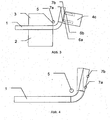
- Fig. 1 is as a workpiece to be deformed a metal sheet 1 clamped between a fixed lower beam 2 and the sheet firmly clamped and also immovable during the deformation process upper beam 3.
- a movable tool in the form of a bending cheek 4 is pivoted in a circular movement about an axis of rotation 5.
- Two spring-mounted electromechanical buttons 6a, 6b are pressed by the metal sheet 1 inwards.
- a control program monitors during the movement the switching state of the buttons and the position of the bending beam 4 and stores the positions at which the switching state changes. From the two positions and the arrangement of the buttons 6a, 6b, the two measuring points 7a, 7b can be determined by simple geometric calculations at which the tips of the buttons touch the workpiece and the buttons are in the position in which the switching state changes. These two measuring points are located on the surface of the workpiece in the form of the metal sheet 1. The metal sheet 1 is already in its stable end position in this state, since it is no longer touched by the bending cheek 4. On the metal sheet 1, only the small forces of the spring-mounted button 6a, 6b, but they can be neglected.
- Fig. 4 the metal sheet 1 is dashed in the desired final state and shown in the actual final state.
- the two determined measurement points 7a, 7b on the sheet surface are after Fig. 5 used to construct a connecting line 8 which coincides with the sheet surface in the straight section. From the course of the connecting straight line, the actual bending angle 9 and the actual radius 10, which corresponds to the distance of the connecting straight line 8 from the pivot point 5, can be determined by simple geometrical calculations.
- the difference between the swing angle W1 of the bending beam 4 and the actual angle 9 on the metal sheet 1 can be added to the pivoting angle as a correction in future bending operations, which are carried out under the same conditions, to actually reach the desired angle.
- the conditions are then changed in one point:
- the tilt angle is slightly larger.
- the measuring process can be carried out again with the new, corrected swivel angle and a new correction can be determined.
- the actually achieved radius 10 on the metal sheet 1 has an effect on the actual outer dimensions achieved and on the required blank length of the sheet.
- the desired outer dimension can be achieved by correcting the position of the sheet by the difference between the desired and actually achieved radius.
- the required cutting length is determined by using the actual radius reached instead of the desired radius for the cutting calculation.
- Fig. 6 the structure of a sprung mounted electromechanical probe is shown in detail.
- two such buttons 6a, 6b are integrated.
- the right button 6b is enlarged and shown in detail.
- a round plunger 11 is movably mounted in a bore of the bending cheek 4. He is pushed by a coil spring 12 to the outside. The spring force is designed so that the frictional force of the bearing and the weight of the plunger are safely overcome.
- the plunger When the plunger is pressed inwardly against the spring force by the workpiece, it pushes on the pin 13 of a precision switch 14 which has a repeatability of 1 micron.
- distance sensors can be used instead of the two electromechanical buttons with precise switching contacts. These can be designed as contact probes with displacement sensors or as non-contact sensors.
- the control program does not need to monitor the position of the bending cheek 4 and the switching state of the stylus during movement, but to measure after moving the bending beam 4 only once the distance between the two sensors to the workpiece surface.
Landscapes
- Engineering & Computer Science (AREA)
- Mechanical Engineering (AREA)
- Physics & Mathematics (AREA)
- General Physics & Mathematics (AREA)
- Bending Of Plates, Rods, And Pipes (AREA)
Claims (4)
- Procédé pour le mesurage et/ou la correction de la forme de pièces usinées telles que des tôles, des tuyaux, des fils de fer ou autres, après leur déformation par pliage, dans lequel une première section de la pièce usinée est serrée fort, une deuxième section est pliée sur une arête de pliage, en faisant pivoter un outil autour d'un axe de rotation (5), et une partie droite de la deuxième section, consécutive à la pliure, est mesurée quant à sa position par rapport à la première section, après le procédé de pliage, dans lequel au moins deux points de mesurage (7a, 7b), avec chacun un écart différent par rapport à l'arête de pliage, sont calculés dans la région de la partie droite de la deuxième section de la pièce usinée, dont la droite de jonction (8) donne l'angle de pliage réel (9), et dans lequel la différence entre l'angle de pliage réel (9) et un angle de pliage prédéterminé sert de base au calcul du parcours de déformation pour un procédé de pliage final ou itératif suivant,
caractérisé en ce que
les droites de jonction (8) calculées permettent de calculer le rayon de pliure (10) réellement atteint, an tant qu'écart de la droite de jonction (8) calculée par rapport à l'axe de rotation (5), et en ce que la différence de celui-ci par rapport à un rayon de pliure prédéterminé, lors du calcul d'une position corrigée d'une pièce usinée et/ou d'une longueur de découpe de la pièce usinée, sert de base à un procédé de pliage suivant. - Presse plieuse avec un dispositif pour le mesurage et/ou la correction de la forme de pièces usinées, telles que des tôles, des tuyaux, des fils de fer et autres, après leur déformation par pliage, avec une joue inférieure fixe (2) et une jour supérieure (3) également immobile (3) pour le serrage d'une première section de la pièce usinée (1), une joue de pliage (4) pivotante autour d'un axe de rotation (5), pour le pliage d'une deuxième section de la pièce usinée (1) sur une arête de pliage, dans laquelle au moins deux détecteurs (6a, 6b) pour le mesurage de l'écart entre la joue de pliage (4) et la surface de la pièce usinée (1) sont intégrés dans la joue de pliage (4), pour le calcul d'au moins deux points de mesurage (7a, 7b) avec chacun un écart différent par rapport à l'arête de pliage dans la région de la partie droite de la deuxième section de la pièce usinée (1), et avec des moyens pour la détermination de l'angle de pliage réel (9) par le calcul de la droite de jonction par les au moins deux points de mesurage (7a, 7b),
caractérisée par
des moyens pour le calcul du rayon de pliage (10) réellement atteint, en tant qu'écart entre la droite de jonction calculée (8) et l'axe de rotation (5). - Presse plieuse selon la revendication 2,
caractérisée en ce que
en tant que détecteurs sont prévus des palpeurs électromécaniques (6a, 6b), qui coopèrent de telle manière avec des contacts électriques de commutation, que le point de mesurage correspondant est défini à partir de leur position par rapport à la jour de pliage (4) au moment de la commutation. - Presse plieuse selon la revendication 3,
caractérisée en ce que
des détecteurs d'écart sans contact sont prévus pour le mesurage de l'écart, qui commutent lors de l'atteinte d'un certain écart, de sorte que le point de mesurage (7a, 7b) correspondant est défini en fonction de la position de la jour de pliage (4) au moment de la commutation.
Applications Claiming Priority (1)
| Application Number | Priority Date | Filing Date | Title |
|---|---|---|---|
| DE102006050687A DE102006050687B4 (de) | 2006-10-24 | 2006-10-24 | Verfahren zur Messung und/oder Korrektur der Werkstückform nach dem Umformen durch Biegen |
Publications (2)
| Publication Number | Publication Date |
|---|---|
| EP1916498A1 EP1916498A1 (fr) | 2008-04-30 |
| EP1916498B1 true EP1916498B1 (fr) | 2009-05-27 |
Family
ID=38829607
Family Applications (1)
| Application Number | Title | Priority Date | Filing Date |
|---|---|---|---|
| EP07020863A Not-in-force EP1916498B1 (fr) | 2006-10-24 | 2007-10-24 | Procédé de mesure et/ou de correction de la forme d'une pièce à usiner selon la déformation par pliage et presse plieuse destinée à exécuter le procédé |
Country Status (3)
| Country | Link |
|---|---|
| EP (1) | EP1916498B1 (fr) |
| AT (1) | ATE432456T1 (fr) |
| DE (2) | DE102006050687B4 (fr) |
Cited By (1)
| Publication number | Priority date | Publication date | Assignee | Title |
|---|---|---|---|---|
| DE102011006101A1 (de) | 2011-03-25 | 2012-09-27 | Wafios Ag | Verfahren zur Herstellung eines Biegeteils und Biegemaschine zur Durchführung des Verfahrens |
Families Citing this family (4)
| Publication number | Priority date | Publication date | Assignee | Title |
|---|---|---|---|---|
| AU2009244489B2 (en) * | 2008-05-05 | 2015-05-07 | Edgewell Personal Care Brands, Llc | Razor blade and method of manufacture |
| DE102011013701A1 (de) | 2011-03-11 | 2012-09-13 | Jean Finger | Verfahren und Vorrichtung zum winkelgenauen Abkanten oder Biegen von Blechen |
| CN112355102B (zh) * | 2020-12-18 | 2022-11-11 | 山东沃尔斯铜铝业有限公司 | 一种多用铝型材折弯机 |
| CN115055538B (zh) * | 2022-07-14 | 2025-04-11 | 东莞市益松数控科技有限公司 | 弯刀角度检测方法、检测装置及设备 |
Family Cites Families (7)
| Publication number | Priority date | Publication date | Assignee | Title |
|---|---|---|---|---|
| DE2044199C3 (de) * | 1970-09-07 | 1974-12-05 | Karl Mengele & Soehne Maschinenfabrik Und Eisengiesserei Guenzburg-Donau, 8870 Guenzburg | Winkelmeß- und Steuereinrichtung an Biege- insbesondere Freibiegemaschinen |
| DE3008701A1 (de) * | 1980-03-07 | 1981-09-24 | Johann 7057 Leutenbach Hess | Winkelmessvorrichtung fuer abkantpressen |
| EP0237543A1 (fr) * | 1985-09-19 | 1987-09-23 | GARDNER, Robert Frederick | Machine a cintrer les tubes |
| US4864509A (en) * | 1987-09-29 | 1989-09-05 | The Boeing Company | Method and related apparatus for controlling the operation of a press brake |
| JPH0217404A (ja) * | 1988-07-05 | 1990-01-22 | Matsushita Electric Works Ltd | 曲げ角度測定方法 |
| IT1260892B (it) * | 1993-02-23 | 1996-04-29 | Prima Ind Spa | Dispositivo per misurare l'angolo di un pezzo, in particolare l'angolodi piegatura di un pezzo di lamiera. |
| JP3393065B2 (ja) * | 1998-06-19 | 2003-04-07 | 株式会社関電工 | 鋼管布設現場における鋼管曲げ加工用折り尺状曲げ尺およびそれを用いた鋼管曲げ加工方法 |
-
2006
- 2006-10-24 DE DE102006050687A patent/DE102006050687B4/de not_active Expired - Fee Related
-
2007
- 2007-10-24 DE DE502007000771T patent/DE502007000771D1/de active Active
- 2007-10-24 AT AT07020863T patent/ATE432456T1/de not_active IP Right Cessation
- 2007-10-24 EP EP07020863A patent/EP1916498B1/fr not_active Not-in-force
Cited By (3)
| Publication number | Priority date | Publication date | Assignee | Title |
|---|---|---|---|---|
| DE102011006101A1 (de) | 2011-03-25 | 2012-09-27 | Wafios Ag | Verfahren zur Herstellung eines Biegeteils und Biegemaschine zur Durchführung des Verfahrens |
| WO2012130596A2 (fr) | 2011-03-25 | 2012-10-04 | Wafios Ag | Procédé de fabrication d'une pièce pliée et plieuse pour la mise en œuvre du procédé |
| DE102011006101B4 (de) * | 2011-03-25 | 2015-12-24 | Wafios Ag | Verfahren zur Herstellung eines Biegeteils und Biegemaschine zur Durchführung des Verfahrens |
Also Published As
| Publication number | Publication date |
|---|---|
| DE102006050687A1 (de) | 2008-04-30 |
| ATE432456T1 (de) | 2009-06-15 |
| EP1916498A1 (fr) | 2008-04-30 |
| DE102006050687B4 (de) | 2010-01-28 |
| DE502007000771D1 (de) | 2009-07-09 |
Similar Documents
| Publication | Publication Date | Title |
|---|---|---|
| EP2874764B1 (fr) | Presse à cintrer pourvue d'un dispositif de détection d'angle et procédé de détermination de l'angle de pliage | |
| EP1916498B1 (fr) | Procédé de mesure et/ou de correction de la forme d'une pièce à usiner selon la déformation par pliage et presse plieuse destinée à exécuter le procédé | |
| AT516260B1 (de) | Biegewerkzeug mit einer Längsversatz-Messvorrichtung | |
| EP2016368B1 (fr) | Procédé et dispositif de mesure d'un point sur la surface d'une pièce | |
| EP2311583B1 (fr) | Procédé de détermination de l'épaisseur d'une pièce à usiner à l'aide d'une plieuse et une telle plieuse | |
| EP1414610A1 (fr) | Unite de soudage par resistance et procede de commande correspondant | |
| DE202006020110U1 (de) | Schwenkbiegemaschine zur Messung und/oder Korrektur der Werkstückform nach dem Umformen durch Biegen | |
| EP1398094B1 (fr) | Procédé et dispositif pour déterminer la longueur de branche de pièces cintrées | |
| DE19919693C2 (de) | Verfahren zur Positionsbestimmung eines Preßstempels einer Pulverpresse | |
| EP4235325B1 (fr) | Procédé et dispositif de détermination des points de mesure d'une bande de mesure adaptée à la mesure d'un objet de mesure au moyen d'un dispositif de mesure de coordonnés ainsi que programme | |
| DE102005027640B4 (de) | Verfahren und Vorrichtung zum automatischen Biegerichten länglicher Werkstücke | |
| DE4307899C2 (de) | Vorrichtung zum Biegen von auf Festigkeit zu prüfenden Probekörpern | |
| DE19809589A1 (de) | Verfahren zur Kalibrierung eines Tasters eines Koordinatenmeßgerätes | |
| DE10006512C2 (de) | Vorrichtung für eine Abkantpresse zum Messen des Biegewinkels am Werkstück | |
| EP1844889B1 (fr) | Procédé et dispositif destinés au soudage par points sur au moins une électrode de soudure positionnée sur une pièce usinée à l'aide d'au moins un robot | |
| DE102008063236B4 (de) | Verfahren zum Kalibrieren einer Messkraft an einem Koordinatenmessgerät | |
| AT411022B (de) | Verfahren zur reduktion der biegewinkelfehler beim gesenkbiegen | |
| EP1635972B1 (fr) | Procede et dispositif pour travailler des pieces par formage | |
| EP1780846B1 (fr) | Tête de mesure et procédé de détermination de hauteur de sertissage d'un conducteur | |
| EP1707915B1 (fr) | Procédé pour mesurer une pièce supportée dans une position de référence | |
| DE4301486C1 (de) | Vorrichtung zur automatischen Kompensation von Ungenauigkeiten an Schleifmaschinen | |
| EP1893941B1 (fr) | Procede et dispositif pour determiner des parametres geometriques d'un objet de mesure conique | |
| DE102018206232A1 (de) | Verfahren zum Detektieren einer Fehlstellung einer Schneidoptik einer Laserschneidmaschine, Auswerteeinrichtung und Laserschneidmaschine | |
| EP0744592A2 (fr) | Méthode et dispositif de mesure d'angles, en particulier d'angles de flexion de tÔles | |
| DE102015226385A1 (de) | Verfahren zur Ermittlung eines Messfehlers und zum Vermessen eines Werkstücks mit einem Koordinatenmessgerät |
Legal Events
| Date | Code | Title | Description |
|---|---|---|---|
| PUAI | Public reference made under article 153(3) epc to a published international application that has entered the european phase |
Free format text: ORIGINAL CODE: 0009012 |
|
| AK | Designated contracting states |
Kind code of ref document: A1 Designated state(s): AT BE BG CH CY CZ DE DK EE ES FI FR GB GR HU IE IS IT LI LT LU LV MC MT NL PL PT RO SE SI SK TR |
|
| AX | Request for extension of the european patent |
Extension state: AL BA HR MK RS |
|
| GRAP | Despatch of communication of intention to grant a patent |
Free format text: ORIGINAL CODE: EPIDOSNIGR1 |
|
| 17P | Request for examination filed |
Effective date: 20080411 |
|
| AKX | Designation fees paid |
Designated state(s): AT BE BG CH CY CZ DE DK EE ES FI FR GB GR HU IE IS IT LI LT LU LV MC MT NL PL PT RO SE SI SK TR |
|
| GRAS | Grant fee paid |
Free format text: ORIGINAL CODE: EPIDOSNIGR3 |
|
| GRAA | (expected) grant |
Free format text: ORIGINAL CODE: 0009210 |
|
| AK | Designated contracting states |
Kind code of ref document: B1 Designated state(s): AT BE BG CH CY CZ DE DK EE ES FI FR GB GR HU IE IS IT LI LT LU LV MC MT NL PL PT RO SE SI SK TR |
|
| REG | Reference to a national code |
Ref country code: GB Ref legal event code: FG4D Free format text: NOT ENGLISH |
|
| REG | Reference to a national code |
Ref country code: CH Ref legal event code: EP |
|
| REG | Reference to a national code |
Ref country code: IE Ref legal event code: FG4D Free format text: LANGUAGE OF EP DOCUMENT: GERMAN |
|
| REF | Corresponds to: |
Ref document number: 502007000771 Country of ref document: DE Date of ref document: 20090709 Kind code of ref document: P |
|
| PG25 | Lapsed in a contracting state [announced via postgrant information from national office to epo] |
Ref country code: LT Free format text: LAPSE BECAUSE OF FAILURE TO SUBMIT A TRANSLATION OF THE DESCRIPTION OR TO PAY THE FEE WITHIN THE PRESCRIBED TIME-LIMIT Effective date: 20090527 Ref country code: PT Free format text: LAPSE BECAUSE OF FAILURE TO SUBMIT A TRANSLATION OF THE DESCRIPTION OR TO PAY THE FEE WITHIN THE PRESCRIBED TIME-LIMIT Effective date: 20090927 Ref country code: FI Free format text: LAPSE BECAUSE OF FAILURE TO SUBMIT A TRANSLATION OF THE DESCRIPTION OR TO PAY THE FEE WITHIN THE PRESCRIBED TIME-LIMIT Effective date: 20090527 |
|
| NLV1 | Nl: lapsed or annulled due to failure to fulfill the requirements of art. 29p and 29m of the patents act | ||
| PG25 | Lapsed in a contracting state [announced via postgrant information from national office to epo] |
Ref country code: SE Free format text: LAPSE BECAUSE OF FAILURE TO SUBMIT A TRANSLATION OF THE DESCRIPTION OR TO PAY THE FEE WITHIN THE PRESCRIBED TIME-LIMIT Effective date: 20090827 Ref country code: LV Free format text: LAPSE BECAUSE OF FAILURE TO SUBMIT A TRANSLATION OF THE DESCRIPTION OR TO PAY THE FEE WITHIN THE PRESCRIBED TIME-LIMIT Effective date: 20090527 Ref country code: IS Free format text: LAPSE BECAUSE OF FAILURE TO SUBMIT A TRANSLATION OF THE DESCRIPTION OR TO PAY THE FEE WITHIN THE PRESCRIBED TIME-LIMIT Effective date: 20090927 Ref country code: NL Free format text: LAPSE BECAUSE OF FAILURE TO SUBMIT A TRANSLATION OF THE DESCRIPTION OR TO PAY THE FEE WITHIN THE PRESCRIBED TIME-LIMIT Effective date: 20090527 Ref country code: PL Free format text: LAPSE BECAUSE OF FAILURE TO SUBMIT A TRANSLATION OF THE DESCRIPTION OR TO PAY THE FEE WITHIN THE PRESCRIBED TIME-LIMIT Effective date: 20090527 Ref country code: SI Free format text: LAPSE BECAUSE OF FAILURE TO SUBMIT A TRANSLATION OF THE DESCRIPTION OR TO PAY THE FEE WITHIN THE PRESCRIBED TIME-LIMIT Effective date: 20090527 |
|
| REG | Reference to a national code |
Ref country code: IE Ref legal event code: FD4D |
|
| PG25 | Lapsed in a contracting state [announced via postgrant information from national office to epo] |
Ref country code: CZ Free format text: LAPSE BECAUSE OF FAILURE TO SUBMIT A TRANSLATION OF THE DESCRIPTION OR TO PAY THE FEE WITHIN THE PRESCRIBED TIME-LIMIT Effective date: 20090527 Ref country code: RO Free format text: LAPSE BECAUSE OF FAILURE TO SUBMIT A TRANSLATION OF THE DESCRIPTION OR TO PAY THE FEE WITHIN THE PRESCRIBED TIME-LIMIT Effective date: 20090527 Ref country code: IE Free format text: LAPSE BECAUSE OF FAILURE TO SUBMIT A TRANSLATION OF THE DESCRIPTION OR TO PAY THE FEE WITHIN THE PRESCRIBED TIME-LIMIT Effective date: 20090527 Ref country code: DK Free format text: LAPSE BECAUSE OF FAILURE TO SUBMIT A TRANSLATION OF THE DESCRIPTION OR TO PAY THE FEE WITHIN THE PRESCRIBED TIME-LIMIT Effective date: 20090527 Ref country code: EE Free format text: LAPSE BECAUSE OF FAILURE TO SUBMIT A TRANSLATION OF THE DESCRIPTION OR TO PAY THE FEE WITHIN THE PRESCRIBED TIME-LIMIT Effective date: 20090527 Ref country code: ES Free format text: LAPSE BECAUSE OF FAILURE TO SUBMIT A TRANSLATION OF THE DESCRIPTION OR TO PAY THE FEE WITHIN THE PRESCRIBED TIME-LIMIT Effective date: 20090907 |
|
| PG25 | Lapsed in a contracting state [announced via postgrant information from national office to epo] |
Ref country code: SK Free format text: LAPSE BECAUSE OF FAILURE TO SUBMIT A TRANSLATION OF THE DESCRIPTION OR TO PAY THE FEE WITHIN THE PRESCRIBED TIME-LIMIT Effective date: 20090527 |
|
| PG25 | Lapsed in a contracting state [announced via postgrant information from national office to epo] |
Ref country code: BG Free format text: LAPSE BECAUSE OF FAILURE TO SUBMIT A TRANSLATION OF THE DESCRIPTION OR TO PAY THE FEE WITHIN THE PRESCRIBED TIME-LIMIT Effective date: 20090827 |
|
| PLBE | No opposition filed within time limit |
Free format text: ORIGINAL CODE: 0009261 |
|
| STAA | Information on the status of an ep patent application or granted ep patent |
Free format text: STATUS: NO OPPOSITION FILED WITHIN TIME LIMIT |
|
| BERE | Be: lapsed |
Owner name: HANS SCHRODER MASCHINENBAU G.M.B.H. Effective date: 20091031 |
|
| 26N | No opposition filed |
Effective date: 20100302 |
|
| PG25 | Lapsed in a contracting state [announced via postgrant information from national office to epo] |
Ref country code: MC Free format text: LAPSE BECAUSE OF NON-PAYMENT OF DUE FEES Effective date: 20091031 |
|
| REG | Reference to a national code |
Ref country code: FR Ref legal event code: ST Effective date: 20100630 |
|
| PG25 | Lapsed in a contracting state [announced via postgrant information from national office to epo] |
Ref country code: FR Free format text: LAPSE BECAUSE OF NON-PAYMENT OF DUE FEES Effective date: 20091102 |
|
| PG25 | Lapsed in a contracting state [announced via postgrant information from national office to epo] |
Ref country code: GR Free format text: LAPSE BECAUSE OF FAILURE TO SUBMIT A TRANSLATION OF THE DESCRIPTION OR TO PAY THE FEE WITHIN THE PRESCRIBED TIME-LIMIT Effective date: 20090828 Ref country code: BE Free format text: LAPSE BECAUSE OF NON-PAYMENT OF DUE FEES Effective date: 20091031 |
|
| PG25 | Lapsed in a contracting state [announced via postgrant information from national office to epo] |
Ref country code: AT Free format text: LAPSE BECAUSE OF NON-PAYMENT OF DUE FEES Effective date: 20091024 |
|
| PG25 | Lapsed in a contracting state [announced via postgrant information from national office to epo] |
Ref country code: IT Free format text: LAPSE BECAUSE OF FAILURE TO SUBMIT A TRANSLATION OF THE DESCRIPTION OR TO PAY THE FEE WITHIN THE PRESCRIBED TIME-LIMIT Effective date: 20090527 |
|
| PG25 | Lapsed in a contracting state [announced via postgrant information from national office to epo] |
Ref country code: LU Free format text: LAPSE BECAUSE OF NON-PAYMENT OF DUE FEES Effective date: 20091024 Ref country code: MT Free format text: LAPSE BECAUSE OF FAILURE TO SUBMIT A TRANSLATION OF THE DESCRIPTION OR TO PAY THE FEE WITHIN THE PRESCRIBED TIME-LIMIT Effective date: 20090527 |
|
| PG25 | Lapsed in a contracting state [announced via postgrant information from national office to epo] |
Ref country code: HU Free format text: LAPSE BECAUSE OF FAILURE TO SUBMIT A TRANSLATION OF THE DESCRIPTION OR TO PAY THE FEE WITHIN THE PRESCRIBED TIME-LIMIT Effective date: 20091128 |
|
| PG25 | Lapsed in a contracting state [announced via postgrant information from national office to epo] |
Ref country code: TR Free format text: LAPSE BECAUSE OF FAILURE TO SUBMIT A TRANSLATION OF THE DESCRIPTION OR TO PAY THE FEE WITHIN THE PRESCRIBED TIME-LIMIT Effective date: 20090527 |
|
| PG25 | Lapsed in a contracting state [announced via postgrant information from national office to epo] |
Ref country code: CY Free format text: LAPSE BECAUSE OF FAILURE TO SUBMIT A TRANSLATION OF THE DESCRIPTION OR TO PAY THE FEE WITHIN THE PRESCRIBED TIME-LIMIT Effective date: 20090527 |
|
| REG | Reference to a national code |
Ref country code: CH Ref legal event code: PL |
|
| GBPC | Gb: european patent ceased through non-payment of renewal fee |
Effective date: 20111024 |
|
| PG25 | Lapsed in a contracting state [announced via postgrant information from national office to epo] |
Ref country code: CH Free format text: LAPSE BECAUSE OF NON-PAYMENT OF DUE FEES Effective date: 20111031 Ref country code: LI Free format text: LAPSE BECAUSE OF NON-PAYMENT OF DUE FEES Effective date: 20111031 |
|
| PG25 | Lapsed in a contracting state [announced via postgrant information from national office to epo] |
Ref country code: GB Free format text: LAPSE BECAUSE OF NON-PAYMENT OF DUE FEES Effective date: 20111024 |
|
| PGFP | Annual fee paid to national office [announced via postgrant information from national office to epo] |
Ref country code: DE Payment date: 20221222 Year of fee payment: 16 |
|
| REG | Reference to a national code |
Ref country code: DE Ref legal event code: R119 Ref document number: 502007000771 Country of ref document: DE |
|
| PG25 | Lapsed in a contracting state [announced via postgrant information from national office to epo] |
Ref country code: DE Free format text: LAPSE BECAUSE OF NON-PAYMENT OF DUE FEES Effective date: 20240501 |