EP1916499A1 - Interface utilisateur pour un outil utlisé pour définir une région courbe d'intérêt dans un système visuel d'inspection - Google Patents
Interface utilisateur pour un outil utlisé pour définir une région courbe d'intérêt dans un système visuel d'inspection Download PDFInfo
- Publication number
- EP1916499A1 EP1916499A1 EP07118455A EP07118455A EP1916499A1 EP 1916499 A1 EP1916499 A1 EP 1916499A1 EP 07118455 A EP07118455 A EP 07118455A EP 07118455 A EP07118455 A EP 07118455A EP 1916499 A1 EP1916499 A1 EP 1916499A1
- Authority
- EP
- European Patent Office
- Prior art keywords
- roi
- arc
- curvature
- mode
- parameter control
- Prior art date
- Legal status (The legal status is an assumption and is not a legal conclusion. Google has not performed a legal analysis and makes no representation as to the accuracy of the status listed.)
- Granted
Links
Images


Classifications
-
- G—PHYSICS
- G01—MEASURING; TESTING
- G01B—MEASURING LENGTH, THICKNESS OR SIMILAR LINEAR DIMENSIONS; MEASURING ANGLES; MEASURING AREAS; MEASURING IRREGULARITIES OF SURFACES OR CONTOURS
- G01B11/00—Measuring arrangements characterised by the use of optical techniques
- G01B11/002—Measuring arrangements characterised by the use of optical techniques for measuring two or more coordinates
- G01B11/005—Measuring arrangements characterised by the use of optical techniques for measuring two or more coordinates coordinate measuring machines
-
- G—PHYSICS
- G01—MEASURING; TESTING
- G01B—MEASURING LENGTH, THICKNESS OR SIMILAR LINEAR DIMENSIONS; MEASURING ANGLES; MEASURING AREAS; MEASURING IRREGULARITIES OF SURFACES OR CONTOURS
- G01B11/00—Measuring arrangements characterised by the use of optical techniques
- G01B11/24—Measuring arrangements characterised by the use of optical techniques for measuring contours or curvatures
-
- G—PHYSICS
- G06—COMPUTING OR CALCULATING; COUNTING
- G06F—ELECTRIC DIGITAL DATA PROCESSING
- G06F3/00—Input arrangements for transferring data to be processed into a form capable of being handled by the computer; Output arrangements for transferring data from processing unit to output unit, e.g. interface arrangements
- G06F3/01—Input arrangements or combined input and output arrangements for interaction between user and computer
- G06F3/048—Interaction techniques based on graphical user interfaces [GUI]
- G06F3/0484—Interaction techniques based on graphical user interfaces [GUI] for the control of specific functions or operations, e.g. selecting or manipulating an object, an image or a displayed text element, setting a parameter value or selecting a range
- G06F3/04845—Interaction techniques based on graphical user interfaces [GUI] for the control of specific functions or operations, e.g. selecting or manipulating an object, an image or a displayed text element, setting a parameter value or selecting a range for image manipulation, e.g. dragging, rotation, expansion or change of colour
-
- G—PHYSICS
- G06—COMPUTING OR CALCULATING; COUNTING
- G06T—IMAGE DATA PROCESSING OR GENERATION, IN GENERAL
- G06T7/00—Image analysis
- G06T7/0002—Inspection of images, e.g. flaw detection
- G06T7/0004—Industrial image inspection
-
- G—PHYSICS
- G06—COMPUTING OR CALCULATING; COUNTING
- G06V—IMAGE OR VIDEO RECOGNITION OR UNDERSTANDING
- G06V10/00—Arrangements for image or video recognition or understanding
- G06V10/20—Image preprocessing
- G06V10/22—Image preprocessing by selection of a specific region containing or referencing a pattern; Locating or processing of specific regions to guide the detection or recognition
- G06V10/235—Image preprocessing by selection of a specific region containing or referencing a pattern; Locating or processing of specific regions to guide the detection or recognition based on user input or interaction
-
- G—PHYSICS
- G06—COMPUTING OR CALCULATING; COUNTING
- G06T—IMAGE DATA PROCESSING OR GENERATION, IN GENERAL
- G06T2200/00—Indexing scheme for image data processing or generation, in general
- G06T2200/24—Indexing scheme for image data processing or generation, in general involving graphical user interfaces [GUIs]
-
- G—PHYSICS
- G06—COMPUTING OR CALCULATING; COUNTING
- G06V—IMAGE OR VIDEO RECOGNITION OR UNDERSTANDING
- G06V2201/00—Indexing scheme relating to image or video recognition or understanding
- G06V2201/06—Recognition of objects for industrial automation
Definitions
- the invention relates generally to machine vision inspection systems, and more particularly to video metrology tool modes and tools usable to define inspection operations for such systems.
- Precision machine vision inspection systems can be utilized to obtain precise dimensional measurements of inspected objects and to inspect various other object characteristics.
- Such systems may include a computer, a camera and optical system, and a precision stage that is movable in multiple directions so as to allow the camera to scan the features of a workpiece that is being inspected.
- One exemplary prior art system that is commercially available is the QUICKVISION ® series of PC-based vision systems and QVPAK ® software available from Mitutoyo America Corporation (MAC), located in Aurora, IL.
- Machine vision inspection systems generally utilize automated video inspection.
- U.S. Patent No.6,542,180 (the '180patent) teaches various aspects of such automated video inspection and is incorporated herein by reference in its entirety.
- automated video inspection metrology instruments generally have a programming capability that allows an automatic inspection event sequence to be defined by the user for each particular workpiece configuration. This can be implemented by text-based programming, for example, or through a recording mode which progressively "learns" the inspection event sequence by storing a sequence of machine control instructions corresponding to a sequence of inspection operations performed by a user, or through a combination of both methods.
- Such a recording mode is often referred to as “learn mode” or “training mode.”
- the machine control instructions including the specific inspection event sequence are generally stored as a "part program" or "workpiece program” that is specific to the particular workpiece configuration.
- a part program defines how to acquire each image, such as how to position the camera relative to the workpiece, at what lighting level, at what magnification level, etc.
- the part program defines how to analyze/inspect an acquired image, for example, by using one or more video tools such as edge/boundary detection video tools.
- Video tools may be used manually to accomplish manual inspection and/or machine control operations. Their set-up parameters and operation can also be recorded during learn mode, in order to create automatic inspection programs, or "partprograms.”
- Such tools may include, for example, edge/boundary detection tools, autofocus tools, shape or pattern matching tools, dimension measuring tools, and the like.
- edge/boundary detection tools such as edge/boundary detection tools, autofocus tools, shape or pattern matching tools, dimension measuring tools, and the like.
- Such tools are routinely used in a variety of commercially available machine vision inspection systems, such as the QUICK VISION ® series of vision systems and the associated QVPAK ® software, discussed above.
- GUI graphical user interface
- ROI regions of interest
- Existing alternatives may be difficult to adapt for efficient use with different applications or workpieces.
- Existing user interfaces may be difficult for users to understand intuitively, making user learning and retention difficult.
- Video tools that overcome these and other disadvantages, to allow more efficient, intuitive, and flexible use of precision machine vision inspection systems, would be desirable.
- the users of precision machine vision inspection systems may spend a majority of their part-programming time setting up video tools and adjusting their parameters.
- their GUI features, and other ergonomic factors may be highly valued.
- One type of video tool a so-called "arc tool” for measuring the characteristics of arc-shaped features in images, may have more controllable parameters than a variety of other video tools.
- Arc tool customization has been inconvenient and non-intuitive, especially for large and small arc radii. Accordingly, the present invention is directed toward novel and efficient features for configuring an arc video tool in an easy-to-use and flexible manner.
- a system and method are provided which allow users to define and/or edit tool parameters for an arc tool ROI with a relatively reduced number of operations.
- a unique combination of arc tool user interface features and operations are provided for efficiently editing an arc tool ROI.
- a plurality of distinct types of ROI parameter control features are provide in an arc tool GUI.
- the distinct types of ROI parameter control features may be distinguished by their locations relative to the ROI, and/or each other, and/or by distinct symbols, or the like.
- each distinct type of ROI parameter control feature may be associated with a distinct mode of operation that is specific to that type of ROI parameter control feature.
- activating such a distinct mode of operation may be associated with displaying a corresponding unique mode symbol cursor.
- each of the distinct modes of operation may be activated by an identical activation operation for each of the distinct types of ROI parameter control features.
- the identical activation operation comprises hovering a default cursor over a distinct type of ROI parameter control feature until a unique mode symbol cursor is displayed, then activating the corresponding editing mode by depressing the left mouse button while the unique mode symbol cursor is displayed.
- one distinct mode of operation that is specific to a first type of ROI parameter control feature is a curvature-changing mode, wherein moving a curvature-changing mode symbol cursor along a radial direction causes the nominal radius of curvature of the inner and outer radii of the ROI to mutually decrease or mutually increase, depending on the direction of the radial movement of the curvature-changing mode symbol cursor.
- the curvature-changing mode operates such that the end portions of the ROI, retain their original length and pivot about their midpoints, as the nominal radius of curvature changes.
- the curvature-changing mode is disabled for that ROI.
- the corresponding first type of ROI parameter control feature comprises an editing handle located approximately at the midpoint of at least one of the inner radius boundary of the ROI and the outer radius boundary of the ROI.
- the curvature-changing mode symbol cursor may comprise two arc-shaped lines and at least one arrow oriented transverse to the arc-shaped lines.
- one distinct mode of operation that is specific to a second type of ROI parameter control feature is a symmetrical radial dimension changing mode, wherein moving a symmetrical radial dimension changing mode symbol cursor along a radial direction causes the nominal radius of curvature of the ROI outer radius to increase while the nominal radius of curvature of the ROI inner radius simultaneous decreases by the same amount, or vice versa, depending on the direction of the radial movement of the symmetrical radial dimension changing mode symbol cursor.
- the symmetrical radial dimension changing mode operates such that the end portions of the ROI retain their original angles and midpoints, as the nominal radius of curvature changes.
- one or more of the distinct types of ROI parameter control features may be associated with at least two modes of operation.
- One of the two modes of operation may be shared with at least one other distinct type of ROI parameter control feature.
- three distinct types of ROI parameter control features are located on each of the inner and outer radius boundaries of the ROI.
- Each of these distinct types of ROI parameter control features shares an in-place ROI rotation mode of operation.
- the in-place ROI rotation mode made be activated by an identical activation operation for each of these distinct types of ROI parameter control features.
- the identical activation operation comprises positioning a cursor on one of the distinct types of ROI parameter control features and depressing the right mouse button.
- a distinct mode cursor may change to a cursor corresponding to the shared mode that has been activated as a result of depressing the right mouse button.
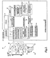
- FIGURE 1 is a block diagram of one exemplary machine vision inspection system 10 usable in accordance with the present invention.
- the machine vision inspection system 10 includes a vision measuring machine 12 that is operably connected to exchange data and control signals with a controlling computer system 14.
- the controlling computer system 14 is further operably connected to exchange data and control signals with a monitor or display 16, a printer 18, a joystick22, a keyboard24, and a mouse26.
- the monitor or display 16 may display a user interface suitable for controlling and/or programming the operations of the machine vision inspection system 10.
- the vision measuring machine 12 includes a moveable workpiece stage32 and an optical imaging system34 which may include a zoom lens or interchangeable lenses.
- the zoom lens or interchangeable lenses generally provide various magnifications for the images provided by the optical imaging system34.
- the machine vision inspection system 10 is generally comparable to the QUICKVISION ® series of vision systems and the QVPAK ® software discussed above, and similar state-of-the-art commercially available precision machine vision inspection systems.
- the machine vision inspection system 10 is also described in copending and commonly assigned U.S. Patent Application No.10/978,227 , which is hereby incorporated herein by reference in its entirety.
- Various aspects of vision measuring machines and control systems are also described in more detail in copending and commonly assigned U.S.
- Patent Application Serial Nos.10/808,948, filed March25, 2004 , and 10/632,823, filed August4, 2003 which are also hereby incorporated herein by reference in their entirety.
- the users of such general purpose precision machine vision inspection systems are often occasional and/or inexperienced users. Such users may spend a majority of their programming time refreshing their understanding of video tools, setting up their ROIs, adjusting their parameters, etc.
- Such users may spend a majority of their programming time refreshing their understanding of video tools, setting up their ROIs, adjusting their parameters, etc.
- even small improvements in the intuitiveness of their graphical user interface and/or their overall ease-of-use, in comparison to their parameter customization capability, their user interface options, and other ergonomic factors may be highly valued.
- FIGURE2 is a diagram of a control system portion 120 and a vision components portion200 of a machine vision inspection system 100 in accordance with the present invention.
- the control system portion 120 is utilized to control the vision components portion200.
- the vision components portion200 includes an optical assembly portion205, light sources220, 230, and240, and a workpiece stage210 having a central transparent portion212.
- the workpiece stage210 is controllably movable along X and Y axes that lie in a plane that is generally parallel to the surface of the stage where a workpiece20 may be positioned.
- the optical assembly portion205 includes a camera system260, an interchangeable objective lens250, and may include a turret lens assembly280, and the coaxial light source230.
- the optical assembly portion205 is controllably movable along a Zaxis that is generally orthogonal to the X and Y axes, by using a controllable motor294 that drives an actuator, a connecting cable, or the like, to move the optical assembly portion205 to change the focus of the image of the workpiece20 captured by the camera system260.
- the controllable motor294 is connected to the input/output interface 130 via a signal line296.
- the term Zaxis refers to the axis that is intended to be used for focusing the image obtained by the optical assembly portion205.
- a workpiece20 that is to be imaged using the machine vision inspection system 100 is placed on the workpiece stage210.
- One or more of a stage light220, a coaxial light230, and a surface light240 may emit source light222, 232, or242, respectively, to illuminate the workpiece20.
- the source light is reflected or transmitted as workpiece light255, which passes through the interchangeable objective lens250 and the turret lens assembly280 and is gathered by the camera system260.
- the image of the workpiece20, captured by the camera system260 is output on a signal line262 to the control system portion120.
- the light sources220, 230, and240 may be connected to the control system portion 120 through signal lines or busses221, 231, and241, respectively.
- the control system portion 120 may rotate the turret lens assembly280 along axis284, between at least the first and second turret lens positions, via control signals through a signal line or bus281.
- control system portion 120 includes a controller 125, an input/output interface 130, a memory 140, a workpiece program generator and executor 170, and a power supply portion190. It will be appreciated that each of these components, as well as the additional components described below, may be interconnected by one or more data/control buses and/or application programming interfaces, or by direct connections between the various elements.
- the input/output interface 130 includes an imaging control interface 131, a motion control interface 132, a lighting control interface 133, and a lens control interface 134.
- the motion control interface 132 includes a position control element 132a, and a speed/acceleration control element 132b.
- the lighting control interface 133 includes lighting control elements 133a-133n, which control, for example, the selection, power, on/off switch, and strobe pulse timing if applicable, for the various corresponding light sources of the machine vision inspection system 100, such as the light sources 220, 230, and240.
- the memory 140 includes an image file memory portion 141, a workpiece program memory portion 142 that may include one or more part programs, or the like, and a video tool portion 143.
- the video tool portion 143 includes a video tool portion 143 a, "TOOL 1", that typifies a plurality of other similar tool portions (not shown), which determine the GUI, image processing operation, etc., for each of the corresponding tools.
- the video tool portion 143 also includes a region of interest generator 143x that supports automatic, semi-automatic and/or manual operations that define various ROIs that are operable in various video tools included in the video tool portion 143.
- the video tool portion 143 includes the arc tool portion 143f, which provides various operations and features as disclosed herein, which define the arc tool user interface and/or which are usable to determine the parameters for various specific instances of applying the arc tool operations to specific workpiece features, as described in greater detail below.
- the memory portion 140 stores data usable to operate the vision system components portion200 to capture or acquire an image of the workpiece20 such that the acquired image of the workpiece20 has desired image characteristics.
- the memory portion 140 further stores data usable to operate the machine vision inspection system 100 to perform various inspection and measurement operations on the acquired images, either manually or automatically, and to output the results through the input/output interface 130.
- the memory portion 140 also contains data defining a graphical user interface operable through the input/output interface 130.
- the signal lines or busses221, 231, and241 of the stage light220, the coaxial light230, and the surface light240, respectively, are all connected to the input/output interface 130.
- the signal line262 from the camera system260 and the signal line296 from the controllable motor294 are connected to the input/output interface 130.
- the signal line262 may carry a signal from the controller 125 that initiates image acquisition.
- One or more display devices 136 and one or more input devices 138 can also be connected to the input/output interface 130.
- the display devices 136 and input devices 138 can be used to display a user interface, which may include various graphical user interface (GUI) features that are usable to perform inspection operations, and/or to create and/or modify part programs, to view the images captured by the camera system260, and/or to directly control the vision system components portion200.
- GUI graphical user interface
- the display devices 136 and/or the input devices 138 may be omitted.
- a user when a user utilizes the machine vision inspection system 100 to create a workpiece image acquisition program for the workpiece20, the user generates workpiece program instructions either by explicitly coding the instructions automatically, semi-automatically, or manually, using a workpiece programming language, or by generating the instructions by moving the machine vision inspection system 100 through an image acquisition training sequence, setting light levels and the like, such that the workpiece program instructions capture the training sequence. This process is repeated for multiple images in a set of images that are to be captured.
- These instructions when executed, will cause the machine vision inspection system to manipulate the workpiece stage210 and/or the camera system260 at certain speed(s) such that a particular portion of the workpiece20 is within the field of view of the camera system260 and at a desired focus state for each of a set of images to be acquired.
- control system 120 executes the instructions and commands the camera system260 to capture one or more images of the workpiece20 according to the instructions.
- the control system 120 will then, under control of the controller 125, input the captured image(s) through the input/output interface 130 and store the captured image(s) in the memory 140.
- the controller 125 may also display the captured images on the display device 136.
- the control system portion 120 is further usable to recall captured and stored workpiece inspection images, to inspect and analyze workpiece features in such workpiece inspection images, and to store and/or output the inspection results.
- These analysis and inspection methods are typically embodied in various video tools included in the video tool portion 143 of the memory 140, including the arc tool portion 143f.
- the control system 120 outputs the results of each analysis/inspection operation to the input/output interface for outputting to various display devices 136, such as a video display, printer, and the like.
- the control system 120 may also store the results of each inspection operation in the memory 140.
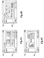
- FIGURE3 is a diagram illustrating one embodiment of a machine vision inspection system user interface display300 including one exemplary arrangement of various features associated with an arc tool.
- the user interface display300 includes a field of view (FOV) window 310 that displays a workpiece image 315 that includes two surfaces316a and316b that abut one another along an edge 317.
- the user interface 300 also includes various measurement and/or operation selection bars such as the selection bars320 and340, a real-time X-Y-Z (position) coordinate window330, and a light control window350.
- the FOV window310 includes one exemplary instance of an arc tool400 superimposed upon the workpiece image 315.
- the appearance of editing handles42X indicates that the arc tool400 has been selected by a user for editing.
- editing handles42X may be displayed or highlighted on the ROI boundary410, and/or the user interface may automatically display an arc tool parameter dialog box, such as the parameter dialog box490 described in greater detail below, or an analogous dialog box.
- FIGURES4A-4C are diagrams illustrating various features of one embodiment of the arc tool parameter dialog box 490.
- a tabbed dialog box configuration is illustrated, which includes user-selectable tabbed portions491a, 491b, and491c.
- FIGURE4A illustrates the tabbed portion491a, which may reflect the X and Y coordinates of the center of curvature of the arc tool, the inner and outer radii of the arc tool ROI, denoted R1 and R2, respectively, as well as the start and stop angles of the defined ROI.
- the start and stop angles correspond to the orientations of the end portions of an arc tool ROI boundary.
- start and stop angles may be defined about the nominal center of the radius of curvature of an arc tool, and in a counterclockwise direction relative to a horizontal reference axis in an image, for example. These values may be determined by graphical definition of the ROI as described further below, and/or they may be entered directly in the dialog box.
- the tabbed portion491a may also reflect the coordinates XS and YS of the edge selector416 (described below with reference to FIGURE 5B).
- FIGURE4B illustrates tabbed portion491b, which reflects the edge search parameters to be employed within the selected ROI.
- the tabbed portion491b may reflect a slope parameter type that specifies whether the edge intensity profile is to exhibit a falling slope (light to dark), a rising slope (dark to light) or any (either) slope when proceeding along the arc edge detection scan line direction indicated by the arc tool, as described further below.
- the tabbed portion491b may reflect a parameter type that specifies whether the edge intensity profile corresponds to a strong edge or a weak edge. Strong edge search criteria may be more stringent to insure higher reliability in the resulting detection. Conversely, weak edge search criteria sacrifice some reliability, in order to make it more likely that the weak edge will be identified.
- the tabbed portion491b may also reflect scan parameters that are used for identifying points along the arc edge in the ROI. Outlier removal may cause geometrically deviant points to be rejected, a scan interval value may cause points to be identified at a spacing of 1 degree, or 5 degrees, etc., and a clockwise or counterclockwise sampling direction may be specified for proceeding with the edge scans.
- FIGURE4C illustrates tabbed portion491c, which includes a portion that allows selection of a type of filter that may be applied to the image data in the ROI before performing edge detection.
- the embodiment shown in FIGURE4C allows the user to select one of four filter types or no filter at all. The user may select a median, an averaging, a Gaussian or a morphology filter.
- the tabbed portion 491c also includes a portion that reflects edge detection threshold values that may govern edge detection operations.
- the embodiment shown in FIGURE4C allows selection of either a static or a dynamic edge threshold.
- the user may specify three values TH, THR, and THS.
- the static threshold value TH defines the mean pixel intensity of the pixels that define an edge.
- the dynamic threshold value THR modifies the value THS at run time.
- the edge strength threshold value THS defines the minimum acceptance threshold for the difference in gray scale intensity of the pixels that define the edge of the surface. These thresholds determine whether an edge point is identified along an edge intensity scan line, or whether a scan "fails.”
- the Defaults button at the bottom restores the entries on the tabbed portions491b and491c to their default values
- the OK button accepts the current parameters and closes the arc tool parameter dialog box490
- the Cancel button returns all parameters to their state before the current editing sequence began and closes the dialog box490.
- FIGURES 5A and5B are diagrams illustrating various features related to arc tool user interface according to this invention.
- FIGURE5A illustrates one embodiment of a tool and/or mode selection bar570, including an arc tool activation button or icon540.
- the arc tool button540 may comprise an "on-off' indicator, such as an indicator box541 that may appear surrounding the arc tool button or icon when it is active.
- an indicator box541 that may appear surrounding the arc tool button or icon when it is active.
- the arc tool button540 becomes inactive when a different button is clicked on the tool and/or mode selection bar570, or another incompatible action is initiated by the user.
- FIGURE 5B shows the FOV window310 and illustrates various features of one embodiment of the arc tool400. Except as otherwise described herein, the FOV window 310, and/or the arc tool400 in the FOV window 310, may operate according to known methods used in commercial systems, if desired.
- FIGURE 5B represents an initial state of one instance of the arc tool400, just after its initial drawing or creation.
- the instance of the arc tool400 is created, with the arc tool button540 active, by positioning a cursor at one point in the FOV window310, depressing the left mouse button, "dragging" the cursor (e.g., approximately as indicated by the length and direction of the arrow591 shown in FIGURE5B), and finally releasing the button to create the initial state of the arc tool400.
- the cursor be dragged across the edge, e.g., the edge317', that is to be inspected using the tool. This generally places the edge within a ROI402 that defines the portion of the image that is processed by the operations of the arc tool.
- the arrow 591 is generally not part of the user interface, but is shown here only for purposes of explanation.
- the arc tool400 may include the ROI402, which is defined by a ROI boundary410 having portions comprising an inner radius410in, an outer radius410out, and first and second ends410e and410e' at respective stop and start angles. Also shown are scan direction indicators412 and412', edge slope indicator414, sampling direction indicator418, and edge selector416.
- the edge selector may be positioned by the user, e.g., by dragging it to a desired position along the edge317', to define a "typical" portion of an edge. The actual edge profile at the location of the edge selector then provides the basis for defining specific edge profile intensity characteristics that aid in reliable edge detection.
- the scan direction indicators412 and412' may comprise arrowheads located along the end portions410e and410e', as shown.
- the arrowheads are configured to point in the direction corresponding to the sequence that is to be used for the analysis of pixel intensity that is used for detecting the edge in an image. It is generally advantageous if the scan direction proceeds from the least textured or "noisy" side of an edge or boundary to the more noisy side of the edge.
- the edge slope indicator414 may generally be filled in an arc tool is trained, to indicate whether the intensity rises or falls across an edge, as described in greater detail below with reference to FIGURE 14.
- FIGURE6 is a diagram illustrating another instance of the FOV window310 and illustrates various additional features of one embodiment of the arc tool400.
- FIGURE6 represents a state of one instance of the arc tool400, wherein the arc tool400 has been selected for editing after its creation.
- an arc tool400 is selected for editing by positioning a cursor in the ROI402, or on the ROI boundary410, and clicking the left mouse button.
- various editing handles appear (e.g., small boxes positioned on the ROI boundary410).
- the editing handles may be "dragged" by using an input device in a known manner, and/or otherwise operated as described herein, in order to modify the ROI parameters of the arc tool400.
- the editing handles are one type of ROI parameter control feature that may be included in an arc tool GUI according to this invention.
- various parameter ROI parameter control features may be of distinct “types” and/or perform distinct operations, depending on their locations.
- the arc tool400 may include a first type of editing handles421-421', which may be located near the middle of the outer radius410out and inner radius410in, respectively. These editing handles may operate as described further below with reference to FIGURE6, and also as described with reference to FIGURES7, 8A-8C, and 13.
- a second type of editing handles423 and423' may be located near the middle of the end portions410e' and410e. These editing handles may operate as described further below with reference to FIGURES 10 and 11.
- a third type of editing handles424-424"' may be located at the corners of the ROI boundary410.
- the third type of editing handles may operate as described further below with reference to FIGURES 9 and 13.
- a fourth type of editing handles426-426"' may be located at two positions on each of the outer radius410out and inner radius410in, inward from the corners of the ROI boundary410. Stated another way, they may be located between the first type of editing handles421-421' and the third type of editing handles424-424"'. In one embodiment, the fourth type of editing handles may operate as described further below with reference to FIGURES 12 and 13.
- the different types of editing handles (or more generally, the different types of ROI parameter control features) that perform distinct operations may be associated with corresponding distinct mode symbol cursors that are activated under certain conditions to become the cursor or mouse-pointer in the FOV window310.
- Various generic GUI operations e.g., a drag operation, and/or right mouse button click, or the like, may have a different result depending on the underlying type of ROI parameter control feature that is associated with the operation. For example, a drag operation associated with a first distinct type of ROI parameter control feature may cause two opposing ROI boundaries to move in opposite directions, while of a drag operation associated with a second distinct type of ROI parameter control feature may cause two opposing ROI boundaries change their radii of curvature by the same amount.
- a distinct mode symbol cursor may be displayed to cue the user regarding the type of ROI parameter control feature that is currently being used and/or the specific result that may be expected from one of the generic GUI operations.
- hovering with the default cursor or mouse-pointer over a particular type of editing handle for a predefined time may cause the corresponding mode symbol cursor to replace the default cursor.
- the user may then actually activate the corresponding mode in order to perform the corresponding type of tool editing or modification operation.
- the mode is activated by the operator performing a mode triggering action, e.g., clicking and/or holding down the left mouse button, after the mode symbol cursor has been displayed.
- FIGURE6 shows one embodiment of a curvature-changing mode symbol cursor491 that is associated with the first type of editing handles421-421'.
- the user may cause the curvature-changing mode symbol cursor491 to be displayed by positioning the mouse cursor to hover over one of the editing handles421 or421' for a predefined time.
- the editing handles may disappear when a mode symbol cursor such as the curvature-changing mode symbol cursor491 is displayed.
- FIGURE7 is a diagram illustrating one embodiment of various additional curvature-changing mode features and operations in an arc tool user interface according to this invention.
- FIGURE7 represents a state of one instance of the arc tool400 after the curvature-changing mode associated with the first type of editing handles421-421' has been activated, after the curvature-changing mode symbol cursor491 is displayed.
- the curvature-changing mode symbol cursor491 moves away from the center of curvature (e.g., by the dragging the cursor while depressing the left mouse button), along a radial direction approximately indicated by the arrow711, causes the nominal radius of curvature of the outer radius410out and inner radius410in to mutually decrease (causing an increase in their apparent curvature).
- the dashed-line boundary410' corresponds to the state of the arc tool400 before the cursor motion
- the solid-line boundary410 corresponds to the state of the arc tool400 after the cursor motion.
- the curvature-changing mode of the arc tool400 operates such that the end portions 410e' and 410e, retain their original length and pivot about their midpoints712 and 713, respectively, as the nominal radius of curvature changes. That is, the end portions410e' and410e act as though they are "pinned" at their midpoints.
- this behavior is exemplary only, and not limiting.
- the curvature-changing mode may be deactivated (e.g., by releasing a mouse button that was depressed in order to drag the cursor491).
- the editing handles and/or other ROI parameter control features of the arc tool400 may reappear in its GUI, such that other types of editing operations may be performed.
- FIGURES8A-8C are diagrams illustrating one embodiment of various additional curvature-changing mode features and operations in an arc tool according to this invention.
- FIGURES 8A-8C represent the limiting states of various allowed geometry changes for the curvature-changing mode of one embodiment of the arc tool400.
- the dashed-line boundaries410' correspond to the state of the arc tool400 before the cursor motion
- the solid-line boundaries410 correspond to the state of the arc tool400 after the cursor motion.
- FIGURE8A illustrates a limiting state of the arc tool400 as the curvature-changing mode symbol cursor491 is moved radially inward, along a direction approximately indicated by the arrow811, causing the nominal radius of curvature of the outer radius410out and inner radius410in to mutually increase.
- the minimum allowed difference between the stop angle812 and the start angle813 of the arc tool400 is 5degrees. In other embodiments, the minimum is 7degrees. Such a minimum tends to increase the reliability of the geometric operations of the arc tool400.
- motions of the curvature-changing mode symbol cursor 491 that would otherwise cause the minimum to be violated are ignored and/or not permitted.
- FIGURE8B and8C illustrate two limiting states of the arc tool400 as the curvature-changing mode symbol cursor491 is moved radially outward, along a direction approximately indicated by the arrow 811', causing the nominal radius of curvature of the outer radius410out and inner radius410in to mutually decrease.
- the maximum allowed difference between the stop angle 812' and the start angle 813' of the arc tool400 that may be set using the curvature-changing mode symbol cursor491 is approximately 180 degrees, or somewhat less.
- the minimum allowed radius of curvature of the inner radius410in is zero units.
- the arc tool400 includes such limits, in various embodiments, motions of the curvature-changing mode cursor491 that would otherwise cause the limits to be violated, are ignored and/or not permitted.
- Such limits avoid ROI distortions and related programming complexity in embodiments of the arc tool400 wherein the end portions410e and410e' are pinned at their midpoints during the curvature-changing mode.
- display of the editing handles421 or421' may be suppressed, and the associated curvature-changing mode outlined above may be disabled.
- FIGURES9-13 are diagrams illustrating exemplary embodiments of various additional features and operations in an arc tool according to this invention.
- the dashed-line boundaries410' correspond to the state of the arc tool400 before the cursor motion
- the solid-line boundaries410 correspond to the state of the arc tool400 after the cursor motion.
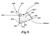
- FIGURE 9 is a diagram illustrating one embodiment of various features and operations of a symmetrical radial dimension changing mode in an arc tool user interface according to this invention.
- FIGURE 9 represents a state of one instance of the arc tool400 after a symmetrical radial dimension changing mode associated with the third type of editing handles424-424"' has been activated, e.g., after a symmetrical radial dimension changing mode symbol cursor492 is displayed.
- This type of operation is advantageous for changing the radial dimension of the ROI402, while its centerline may remain properly located on or near an edge feature (not shown) that is centrally located in the ROI402.
- edge feature not shown
- the mode symbol cursor492 would be displayed proximate to that editing handle, and dragging that instance of the mode symbol cursor492 along the direction indicated by the arrow911', would also have the effect illustrated in FIGURE9, and so on for the editing handles424 and424"'.
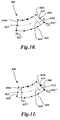
- FIGURE 10 is a diagram illustrating one embodiment of various features and operations of an individual start/stop angle changing mode in an arc tool user interface according to this invention.
- FIGURE 10 represents a state of one instance of the arc tool400 after an individual start/stop angle changing mode associated with the second type of editing handles423-423' has been activated, e.g., after an individual start/stop angle changing mode symbol cursor493 is displayed.
- moving the individual start/stop angle changing mode symbol cursor 493 e.g., by the dragging the cursor while depressing the left mouse button
- causes the stop angle 812" for the end portion 410e to change as shown.
- the mode symbol cursor493 would be displayed proximate to that editing handle 423' where it would instead control the start angle 813" (for the end portion410e') in an analogous manner.
- the start (or stop) angle of the arc tool400 reaches a desired state, that editing operation may be completed and the individual start/stop angle changing mode may be deactivated (e.g., by releasing a mouse button that was depressed in order to drag the mode symbol cursor493).
- FIGURE 11 is a diagram illustrating one embodiment of various features and operations of a rotation about center of curvature mode (RACOC mode) in an arc tool user interface according to this invention.
- FIGURE 11 represents a state of one instance of the arc tool400 after a RACOC mode associated with the second type of editing handles423-423' has been activated, e.g., after a RACOC mode symbol cursor494 is displayed.
- a RACOC mode symbol cursor494 is displayed and the mode is activated simultaneously by depressing the right mouse button.
- the ROI boundary410 behaves as if it were rotated about the center of the radii of curvature of the arc tool400. Moving the cursor in the opposite direction would cause rotation in the opposite direction about the center of the radii of curvature.
- the mode symbol cursor494 would be displayed proximate to that editing handle423' where it would operate in an analogous manner.
- the rotation of the arc tool400 about the center of the radii of curvature reaches a desired state, that editing operation may be completed and the RACOC mode may be deactivated (e.g., by releasing a mouse button that was depressed in order to drag the mode symbol cursor494).
- FIGURE 12 is a diagram illustrating one embodiment of various features and operations of an individual radius changing mode in an arc tool user interface according to this invention.
- FIGURE 12 represents a state of one instance of the arc tool400 after an individual radius changing mode associated with the fourth type of editing handles426-426'" has been activated, e.g., after an individual radius changing mode symbol cursor495 is displayed.
- moving the individual radius changing mode symbol cursor495 away from the center of curvature e.g., by the dragging the cursor while depressing the left mouse button
- a radial direction approximately indicated by the arrow 1211 (or 1211') causes the nominal radius of curvature of the outer radius410out to increase.
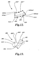
- FIGURE 13 is a diagram illustrating one embodiment of various features and operations of an in-place ROI rotation mode in an arc tool user interface according to this invention.
- the operations of the in-place ROI rotation mode may be performed using any of the previously-described editing handle types, except for the second type of editing handles423-423'.
- the example shown in FIGURE 13 represents a state of one instance of the arc tool400 after the in-place ROI rotation mode has been activated using the editing handle424".
- the in-place ROI rotation mode symbol cursor496 is displayed and the mode is activated simultaneously by depressing the right mouse button with the default cursor on one of the appropriate types of editing handles.
- the editing handles may disappear when the in-place ROI rotation mode is activated.
- the in-place ROI rotation mode symbol cursor496 causes the ROI402 to rotate.
- the cursor496 follows a path that is generally clockwise (or counter-clockwise) about the center of the ROI402, then the ROI402 rotates in a generally clockwise (or counterclockwise) direction.
- the center of rotation of the ROI402 may coincide with the geometric center of the ROI. In another embodiment, the center of rotation of the ROI402 may coincide with the location of the edge selector416.
- the rotation of the arc tool400 When the rotation of the arc tool400 reaches a desired state, that editing operation may be completed and the in-place ROI rotation mode may be deactivated (e.g., by releasing a mouse button that was depressed in order to drag the mode symbol cursor496).
- the editing handles and/or other parameter control features of the arc tool400 may reappear in its GUI, such that other types of editing operations may be performed.
- FIGURE 14 is a diagram illustrating one embodiment of a "run" arc tool400 according to this invention.
- FIGURE 14 represents a state of the arc tool400 after a user has adjusted its ROI parameters and other tool parameters to a desired state for detecting the workpiece edge317'", and furthermore run the arc tool400 to perform the edge detection.
- the detected edge points480 are displayed in the GUI of the arc tool400, and the edge slope indicator414 displayed with a dark semicircle and a lighter semicircle oriented in a manner that corresponds to the relative orientation of the darker (lower intensity) and lighter (higher intensity) sides of the detected edge317"'.
- various tool parameters outlined with reference to FIGURES4A-4C are determined based on the actual image characteristics of the edge317"' in the ROI402.
- FIGURE 15 is a block diagram 700 illustrating various features and operating parameters associated with an arc tool portion743f according to this invention.
- the features and operating parameters of the arc tool portion743f may be implemented in the arc tool portion143f, previously outlined with reference to FIGURE2.
- the various features and operating parameters may be implemented in hardware and/or software by any now-known or later-developed method.
- the arc tool portion743f may comprise an arc tool edit mode portion705, and a tool parameters portion 750.
- the related arc tool parameters comprise location parameters760, "basic” arc tool parameters 770, and "advanced” arc tool parameters 780.
- the location parameters 760 may include arc tool ROI position and size parameters765 and edge selector parameters 766.
- the "basic" arc tool parameters770 may include edge slope parameters775, edge type parameters 776, and edge detection scan parameters 777.
- the "advanced" arc tool parameters780 may include filter type parameters785 and edge detection threshold parameters 786.
- arc tool edit mode portion 705 may comprise a normal mode portion710, a curvature-changing mode portion720, a ROI-rotation mode portion730.
- the normal mode portion710 may include a parameter control feature-type portion715, that may define and control the characteristics and operations associated with each distinct type of parameter control feature that is included in an arc tool GUI and/or any associated menus, or the like.
- the parameter control feature-type portion may define and control the characteristics and operations associated with each of the four distinct types of editing handles, described previously with reference to FIGURES 6-13.
- the curvature-changing mode portion720 and the ROI-rotation mode portion 730 may define and control the mode activation trigger characteristics and operations associated with their respective modes.
- the characteristics and editing operations associated with various exemplary types of parameter control features, and exemplary curvature-changing and ROI-rotation modes have been outlined throughout the previous disclosure, and need not be repeated here.
Landscapes
- Engineering & Computer Science (AREA)
- Physics & Mathematics (AREA)
- General Physics & Mathematics (AREA)
- Theoretical Computer Science (AREA)
- General Engineering & Computer Science (AREA)
- Multimedia (AREA)
- Human Computer Interaction (AREA)
- Quality & Reliability (AREA)
- Computer Vision & Pattern Recognition (AREA)
- Length Measuring Devices By Optical Means (AREA)
- Processing Or Creating Images (AREA)
- Image Processing (AREA)
Applications Claiming Priority (1)
| Application Number | Priority Date | Filing Date | Title |
|---|---|---|---|
| US11/589,125 US7769222B2 (en) | 2006-10-27 | 2006-10-27 | Arc tool user interface |
Publications (2)
| Publication Number | Publication Date |
|---|---|
| EP1916499A1 true EP1916499A1 (fr) | 2008-04-30 |
| EP1916499B1 EP1916499B1 (fr) | 2009-12-16 |
Family
ID=38895953
Family Applications (1)
| Application Number | Title | Priority Date | Filing Date |
|---|---|---|---|
| EP07118455A Active EP1916499B1 (fr) | 2006-10-27 | 2007-10-15 | Interface utilisateur pour un outil utlisé pour définir une région courbe d'intérêt dans un système visuel d'inspection |
Country Status (4)
| Country | Link |
|---|---|
| US (1) | US7769222B2 (fr) |
| EP (1) | EP1916499B1 (fr) |
| JP (1) | JP4950837B2 (fr) |
| DE (1) | DE602007003792D1 (fr) |
Cited By (5)
| Publication number | Priority date | Publication date | Assignee | Title |
|---|---|---|---|---|
| CN103808259A (zh) * | 2012-11-05 | 2014-05-21 | 株式会社三丰 | 边缘测量视频工具参数设置用户界面 |
| CN105988710A (zh) * | 2015-03-17 | 2016-10-05 | 株式会社三丰 | 用于利用触摸显示来协助用户输入的方法 |
| CN106020220A (zh) * | 2016-05-24 | 2016-10-12 | 零度智控(北京)智能科技有限公司 | 无人机、无人机飞行控制方法及装置 |
| CN110360972A (zh) * | 2019-07-10 | 2019-10-22 | Oppo广东移动通信有限公司 | 角度传感器的校准方法、装置、终端及存储介质 |
| EP3875892A1 (fr) * | 2020-03-04 | 2021-09-08 | Carl Zeiss Industrielle Messtechnik GmbH | Appareil de mesure optique, méthode pour générer un programme de mesure optique d'un objet et méthode de mesure optique d'un objet |
Families Citing this family (39)
| Publication number | Priority date | Publication date | Assignee | Title |
|---|---|---|---|---|
| US20130074005A1 (en) * | 2004-11-12 | 2013-03-21 | Cognex Corporation | System, method and graphical user interface for displaying and controlling vision system operating parameters |
| JP4957424B2 (ja) * | 2006-12-08 | 2012-06-20 | セイコーエプソン株式会社 | アイテム編集方法、アイテム編集装置及びそのプログラム |
| US20080320408A1 (en) * | 2007-06-21 | 2008-12-25 | Dziezanowski Joseph J | Devices, Systems, and Methods Regarding Machine Vision User Interfaces |
| US9123093B1 (en) * | 2008-08-29 | 2015-09-01 | Cognex Corporation | Vision inspection programming method and apparatus |
| US11256931B2 (en) * | 2010-04-19 | 2022-02-22 | SMR Patent S.à.r.l | Rearview device simulation |
| US10786736B2 (en) | 2010-05-11 | 2020-09-29 | Sony Interactive Entertainment LLC | Placement of user information in a game space |
| US8269830B1 (en) | 2011-04-14 | 2012-09-18 | Mitutoyo Corporation | Inspecting potentially interfering features in a machine vision system |
| WO2012159123A2 (fr) | 2011-05-19 | 2012-11-22 | Alec Rivers | Outils à guidage automatique |
| JP2013036964A (ja) * | 2011-08-11 | 2013-02-21 | Mitsutoyo Corp | 画像測定装置及び画像測定方法 |
| EP2852868B1 (fr) | 2012-04-26 | 2021-12-01 | Shaper Tools, Inc. | Systèmes et procédés permettant de réaliser une tâche sur un matériau, ou permettant de localiser la position d'un dispositif par rapport à la surface du matériau |
| US9177222B2 (en) * | 2012-11-05 | 2015-11-03 | Mitutoyo Corporation | Edge measurement video tool and interface including automatic parameter set alternatives |
| US8885945B2 (en) | 2012-12-27 | 2014-11-11 | Mitutoyo Corporation | Method for improving repeatability in edge location results of a machine vision inspection system |
| US8917940B2 (en) * | 2013-04-26 | 2014-12-23 | Mitutoyo Corporation | Edge measurement video tool with robust edge discrimination margin |
| JP6195915B2 (ja) * | 2013-05-07 | 2017-09-13 | シャープ株式会社 | 画像計測装置 |
| DE112014002389B4 (de) * | 2013-05-13 | 2022-08-04 | Mitutoyo Corporation | Bearbeitungsumgebung für ein Programm für ein maschinelles Bilderkennungssystem, enthaltend ein betriebskontextbewusstes Kopier-und Einfüge-Merkmal |
| US9639083B2 (en) | 2013-12-18 | 2017-05-02 | Mitutoyo Corporation | System and method for programming workpiece feature inspection operations for a coordinate measuring machine |
| US12295772B2 (en) | 2014-02-25 | 2025-05-13 | DePuy Synthes Products, Inc. | Systems and methods for intra-operative image analysis |
| US10758198B2 (en) * | 2014-02-25 | 2020-09-01 | DePuy Synthes Products, Inc. | Systems and methods for intra-operative image analysis |
| JP6134985B2 (ja) * | 2014-07-31 | 2017-05-31 | 富士フイルム株式会社 | 曲線修正装置および方法並びにプログラム |
| US10580220B2 (en) * | 2015-03-04 | 2020-03-03 | Pixar | Selecting animation manipulators via rollover and dot manipulators |
| CN107530878B (zh) | 2015-05-13 | 2021-01-08 | 整形工具股份有限公司 | 用于被引导工具的系统、方法和设备 |
| US9602715B2 (en) | 2015-07-09 | 2017-03-21 | Mitutoyo Corporation | Adaptable operating frequency of a variable focal length lens in an adjustable magnification optical system |
| US9830694B2 (en) | 2015-08-31 | 2017-11-28 | Mitutoyo Corporation | Multi-level image focus using a tunable lens in a machine vision inspection system |
| US9774765B2 (en) | 2015-09-15 | 2017-09-26 | Mitutoyo Corporation | Chromatic aberration correction in imaging system including variable focal length lens |
| US10055868B2 (en) * | 2016-06-16 | 2018-08-21 | Artaic, Llc | Method of rendering a mosaic design |
| EP3500894B1 (fr) | 2016-08-19 | 2024-05-15 | Shaper Tools, Inc. | Appareil et procédé pour guider un outil placé sur la surface d'un matériau |
| US10943374B2 (en) * | 2017-02-03 | 2021-03-09 | Microsoft Technology Licensing, Llc | Reshaping objects on a canvas in a user interface |
| AU2018206708B2 (en) * | 2017-10-06 | 2021-07-22 | Adobe Inc. | Project faces |
| US11488053B2 (en) | 2017-10-06 | 2022-11-01 | Adobe Inc. | Automatically controlling modifications to typeface designs with machine-learning models |
| US10983679B2 (en) * | 2017-10-06 | 2021-04-20 | Adobe Inc. | Selectively enabling trackpad functionality in graphical interfaces |
| US10339680B2 (en) | 2017-10-06 | 2019-07-02 | Adobe Inc. | Graphics control data for performing skeleton-based modifications of a typeface design |
| IL261733B (en) * | 2018-09-13 | 2022-09-01 | Inspekto A M V Ltd | Streamlining an automatic visual inspection process |
| US11435893B1 (en) | 2021-03-16 | 2022-09-06 | Microsoft Technology Licensing, Llc | Submitting questions using digital ink |
| US11875543B2 (en) | 2021-03-16 | 2024-01-16 | Microsoft Technology Licensing, Llc | Duplicating and aggregating digital ink instances |
| US11526659B2 (en) | 2021-03-16 | 2022-12-13 | Microsoft Technology Licensing, Llc | Converting text to digital ink |
| US11361153B1 (en) | 2021-03-16 | 2022-06-14 | Microsoft Technology Licensing, Llc | Linking digital ink instances using connecting lines |
| US11372486B1 (en) | 2021-03-16 | 2022-06-28 | Microsoft Technology Licensing, Llc | Setting digital pen input mode using tilt angle |
| US11887306B2 (en) | 2021-08-11 | 2024-01-30 | DePuy Synthes Products, Inc. | System and method for intraoperatively determining image alignment |
| US20240005653A1 (en) * | 2022-06-30 | 2024-01-04 | Zebra Technologies Corporation | Systems and Methods for Tool Canvas Metadata & Auto-Configuration in Machine Vision Applications |
Citations (3)
| Publication number | Priority date | Publication date | Assignee | Title |
|---|---|---|---|---|
| US6542180B1 (en) | 2000-01-07 | 2003-04-01 | Mitutoyo Corporation | Systems and methods for adjusting lighting of a part based on a plurality of selected regions of an image of the part |
| JP2004239761A (ja) * | 2003-02-06 | 2004-08-26 | Mitsutoyo Corp | 画像測定装置及びエッジ追跡測定プログラム生成用プログラム |
| EP1686367A2 (fr) | 2005-01-31 | 2006-08-02 | Mitutoyo Corporation | Outil de métrologie vidéo amélioré |
Family Cites Families (9)
| Publication number | Priority date | Publication date | Assignee | Title |
|---|---|---|---|---|
| US6456739B1 (en) * | 1995-06-19 | 2002-09-24 | Canon Kabushiki Kaisha | Apparatus for recognizing characters and a method therefor |
| JP3330014B2 (ja) * | 1996-04-23 | 2002-09-30 | 松下電工株式会社 | 外観検査方法 |
| US6628285B1 (en) * | 1999-02-11 | 2003-09-30 | Autodesk, Inc. | Intelligent drawing redlining and commenting feature |
| JP4477782B2 (ja) * | 2000-01-18 | 2010-06-09 | 株式会社ミツトヨ | 被測定物のイメージにおける複数選択領域該当箇所の照明調整装置及び方法 |
| US7403211B2 (en) * | 2003-02-13 | 2008-07-22 | Lumapix, Inc. | Method and system for interactive region segmentation |
| US20050031191A1 (en) * | 2003-08-04 | 2005-02-10 | Mitutoyo Corporation | Methods and apparatus for inspection of lines embedded in highly textured material |
| US7324682B2 (en) * | 2004-03-25 | 2008-01-29 | Mitutoyo Corporation | System and method for excluding extraneous features from inspection operations performed by a machine vision inspection system |
| US7454053B2 (en) * | 2004-10-29 | 2008-11-18 | Mitutoyo Corporation | System and method for automatically recovering video tools in a vision system |
| US7598968B2 (en) * | 2006-03-27 | 2009-10-06 | Autodesk, Inc. | Network part grips |
-
2006
- 2006-10-27 US US11/589,125 patent/US7769222B2/en active Active
-
2007
- 2007-10-15 EP EP07118455A patent/EP1916499B1/fr active Active
- 2007-10-15 DE DE602007003792T patent/DE602007003792D1/de active Active
- 2007-10-26 JP JP2007279233A patent/JP4950837B2/ja active Active
Patent Citations (3)
| Publication number | Priority date | Publication date | Assignee | Title |
|---|---|---|---|---|
| US6542180B1 (en) | 2000-01-07 | 2003-04-01 | Mitutoyo Corporation | Systems and methods for adjusting lighting of a part based on a plurality of selected regions of an image of the part |
| JP2004239761A (ja) * | 2003-02-06 | 2004-08-26 | Mitsutoyo Corp | 画像測定装置及びエッジ追跡測定プログラム生成用プログラム |
| EP1686367A2 (fr) | 2005-01-31 | 2006-08-02 | Mitutoyo Corporation | Outil de métrologie vidéo amélioré |
Non-Patent Citations (6)
| Title |
|---|
| H. MOTZ: "Microsoft Office PowerPoint 97 for Windows 95/98/NT", January 1999, HERDT VERLAG, pages: 116 - 119 |
| H. MOTZ: "Microsoft PowerPoint 97 for Windows 95/98/NT", January 1999, HERDT VERLAG, NACKENHEIM, XP002464359 * |
| QVPAK 3D CNC VISION MEASURING MACHINE OPERATION GUIDE, September 1996 (1996-09-01) |
| QVPAK 3D CNC VISION MEASURING MACHINE USER'S GUIDE, January 2003 (2003-01-01) |
| T. WEGENER: "Microsoft Office PowerPoint 2003 for Windows", 18 January 2006, HERDT VERLAG, pages: 118 - 119 |
| TINA WEGENER: "Microsoft Office PowerPoint 2003 for Windows", 18 January 2006, HERDT VERLAG FÜR BILDUNGSMEDIEN GMBH, BODENHEIM, XP002464358 * |
Cited By (9)
| Publication number | Priority date | Publication date | Assignee | Title |
|---|---|---|---|---|
| CN103808259A (zh) * | 2012-11-05 | 2014-05-21 | 株式会社三丰 | 边缘测量视频工具参数设置用户界面 |
| CN103808259B (zh) * | 2012-11-05 | 2017-05-10 | 株式会社三丰 | 边缘测量视频工具参数设置用户界面 |
| CN105988710A (zh) * | 2015-03-17 | 2016-10-05 | 株式会社三丰 | 用于利用触摸显示来协助用户输入的方法 |
| CN106020220A (zh) * | 2016-05-24 | 2016-10-12 | 零度智控(北京)智能科技有限公司 | 无人机、无人机飞行控制方法及装置 |
| CN106020220B (zh) * | 2016-05-24 | 2023-12-08 | 零度智控(北京)智能科技有限公司 | 无人机、无人机飞行控制方法及装置 |
| CN110360972A (zh) * | 2019-07-10 | 2019-10-22 | Oppo广东移动通信有限公司 | 角度传感器的校准方法、装置、终端及存储介质 |
| CN110360972B (zh) * | 2019-07-10 | 2020-12-08 | Oppo广东移动通信有限公司 | 角度传感器的校准方法、装置、终端及存储介质 |
| EP3875892A1 (fr) * | 2020-03-04 | 2021-09-08 | Carl Zeiss Industrielle Messtechnik GmbH | Appareil de mesure optique, méthode pour générer un programme de mesure optique d'un objet et méthode de mesure optique d'un objet |
| US11659269B2 (en) | 2020-03-04 | 2023-05-23 | Carl Zeiss Industrielle Messtechnik Gmbh | Optical measuring device |
Also Published As
| Publication number | Publication date |
|---|---|
| EP1916499B1 (fr) | 2009-12-16 |
| US20080101682A1 (en) | 2008-05-01 |
| US7769222B2 (en) | 2010-08-03 |
| DE602007003792D1 (de) | 2010-01-28 |
| JP4950837B2 (ja) | 2012-06-13 |
| JP2008112449A (ja) | 2008-05-15 |
Similar Documents
| Publication | Publication Date | Title |
|---|---|---|
| US7769222B2 (en) | Arc tool user interface | |
| US7570795B2 (en) | Multi-region autofocus tool and mode | |
| EP1686367B2 (fr) | Outil de métrologie vidéo amélioré | |
| US7394926B2 (en) | Magnified machine vision user interface | |
| JP6071452B2 (ja) | マシンビジョンシステムのパートプログラム編集環境内で編集初期化ブロックを利用するシステム及び方法 | |
| JP6239232B2 (ja) | 高性能エッジフォーカスツール | |
| US7522763B2 (en) | Method of measuring occluded features for high precision machine vision metrology | |
| US20110231787A1 (en) | Gui for programming step and repeat operations in a machine vision inspection system | |
| JP5972563B2 (ja) | 構造化照明を用いるエッジ検出 | |
| US8269830B1 (en) | Inspecting potentially interfering features in a machine vision system | |
| US20130027538A1 (en) | Multi-region focus navigation interface | |
| US9444995B2 (en) | System and method for controlling a tracking autofocus (TAF) sensor in a machine vision inspection system | |
| EP1679656A2 (fr) | Sytème et méthode de programmation d'opérations d'interruption pendant des séquences d'acquisition d'images mobiles dans un système de vision | |
| JP2004333500A (ja) | 画像測定システム及びそのプログラミング方法 | |
| EP1653224A1 (fr) | Système à limite floue et méthode de contrôle de systèmes de vision pour une inspection systématiquement précise et à grande vitesse | |
| JP2006127517A (ja) | 機械視覚検査方法およびそのためのユーザーインターフェース | |
| US10539417B2 (en) | Method and device for determining dimensional properties of a measurement object | |
| US9167215B2 (en) | Machine vision system editing environment for a part program in which a continuous stream of image acquisition operations are performed during a run mode | |
| US8689127B1 (en) | Edge measurement video tool parameter-setting user interface | |
| US12574625B2 (en) | System with lighting control including grouped channels |
Legal Events
| Date | Code | Title | Description |
|---|---|---|---|
| PUAI | Public reference made under article 153(3) epc to a published international application that has entered the european phase |
Free format text: ORIGINAL CODE: 0009012 |
|
| AK | Designated contracting states |
Kind code of ref document: A1 Designated state(s): AT BE BG CH CY CZ DE DK EE ES FI FR GB GR HU IE IS IT LI LT LU LV MC MT NL PL PT RO SE SI SK TR |
|
| AX | Request for extension of the european patent |
Extension state: AL BA HR MK RS |
|
| 17P | Request for examination filed |
Effective date: 20081020 |
|
| 17Q | First examination report despatched |
Effective date: 20081120 |
|
| AKX | Designation fees paid |
Designated state(s): DE FR GB |
|
| GRAP | Despatch of communication of intention to grant a patent |
Free format text: ORIGINAL CODE: EPIDOSNIGR1 |
|
| GRAS | Grant fee paid |
Free format text: ORIGINAL CODE: EPIDOSNIGR3 |
|
| GRAA | (expected) grant |
Free format text: ORIGINAL CODE: 0009210 |
|
| AK | Designated contracting states |
Kind code of ref document: B1 Designated state(s): DE FR GB |
|
| REG | Reference to a national code |
Ref country code: GB Ref legal event code: FG4D |
|
| REF | Corresponds to: |
Ref document number: 602007003792 Country of ref document: DE Date of ref document: 20100128 Kind code of ref document: P |
|
| PLBE | No opposition filed within time limit |
Free format text: ORIGINAL CODE: 0009261 |
|
| STAA | Information on the status of an ep patent application or granted ep patent |
Free format text: STATUS: NO OPPOSITION FILED WITHIN TIME LIMIT |
|
| 26N | No opposition filed |
Effective date: 20100917 |
|
| PG25 | Lapsed in a contracting state [announced via postgrant information from national office to epo] |
Ref country code: FR Free format text: LAPSE BECAUSE OF NON-PAYMENT OF DUE FEES Effective date: 20101102 |
|
| REG | Reference to a national code |
Ref country code: FR Ref legal event code: ST Effective date: 20110630 |
|
| REG | Reference to a national code |
Ref country code: DE Ref legal event code: R082 Ref document number: 602007003792 Country of ref document: DE Representative=s name: KEIL & SCHAAFHAUSEN PATENTANWAELTE PARTGMBB, DE Ref country code: DE Ref legal event code: R082 Ref document number: 602007003792 Country of ref document: DE Representative=s name: KEIL & SCHAAFHAUSEN PATENT- UND RECHTSANWAELTE, DE |
|
| PGFP | Annual fee paid to national office [announced via postgrant information from national office to epo] |
Ref country code: DE Payment date: 20251021 Year of fee payment: 19 |
|
| PGFP | Annual fee paid to national office [announced via postgrant information from national office to epo] |
Ref country code: GB Payment date: 20251022 Year of fee payment: 19 |