EP1916756A2 - Anordnung zur Verbindung der elektrischen Statorwicklungen eines elektrischen Motors - Google Patents
Anordnung zur Verbindung der elektrischen Statorwicklungen eines elektrischen Motors Download PDFInfo
- Publication number
- EP1916756A2 EP1916756A2 EP07118734A EP07118734A EP1916756A2 EP 1916756 A2 EP1916756 A2 EP 1916756A2 EP 07118734 A EP07118734 A EP 07118734A EP 07118734 A EP07118734 A EP 07118734A EP 1916756 A2 EP1916756 A2 EP 1916756A2
- Authority
- EP
- European Patent Office
- Prior art keywords
- connector
- electrical
- electric motor
- electrical terminals
- passage
- Prior art date
- Legal status (The legal status is an assumption and is not a legal conclusion. Google has not performed a legal analysis and makes no representation as to the accuracy of the status listed.)
- Withdrawn
Links
Images


Classifications
-
- H—ELECTRICITY
- H02—GENERATION; CONVERSION OR DISTRIBUTION OF ELECTRIC POWER
- H02K—DYNAMO-ELECTRIC MACHINES
- H02K5/00—Casings; Enclosures; Supports
- H02K5/04—Casings or enclosures characterised by the shape, form or construction thereof
- H02K5/22—Auxiliary parts of casings not covered by groups H02K5/06-H02K5/20, e.g. shaped to form connection boxes or terminal boxes
- H02K5/225—Terminal boxes or connection arrangements
-
- H—ELECTRICITY
- H01—ELECTRIC ELEMENTS
- H01R—ELECTRICALLY-CONDUCTIVE CONNECTIONS; STRUCTURAL ASSOCIATIONS OF A PLURALITY OF MUTUALLY-INSULATED ELECTRICAL CONNECTING ELEMENTS; COUPLING DEVICES; CURRENT COLLECTORS
- H01R13/00—Details of coupling devices of the kinds covered by groups H01R12/70 or H01R24/00 - H01R33/00
- H01R13/02—Contact members
- H01R13/10—Sockets for co-operation with pins or blades
- H01R13/11—Resilient sockets
- H01R13/111—Resilient sockets co-operating with pins having a circular transverse section
-
- H—ELECTRICITY
- H01—ELECTRIC ELEMENTS
- H01R—ELECTRICALLY-CONDUCTIVE CONNECTIONS; STRUCTURAL ASSOCIATIONS OF A PLURALITY OF MUTUALLY-INSULATED ELECTRICAL CONNECTING ELEMENTS; COUPLING DEVICES; CURRENT COLLECTORS
- H01R13/00—Details of coupling devices of the kinds covered by groups H01R12/70 or H01R24/00 - H01R33/00
- H01R13/40—Securing contact members in or to a base or case; Insulating of contact members
- H01R13/42—Securing in a demountable manner
- H01R13/422—Securing in resilient one-piece base or case, e.g. by friction; One-piece base or case formed with resilient locking means
-
- H—ELECTRICITY
- H01—ELECTRIC ELEMENTS
- H01R—ELECTRICALLY-CONDUCTIVE CONNECTIONS; STRUCTURAL ASSOCIATIONS OF A PLURALITY OF MUTUALLY-INSULATED ELECTRICAL CONNECTING ELEMENTS; COUPLING DEVICES; CURRENT COLLECTORS
- H01R13/00—Details of coupling devices of the kinds covered by groups H01R12/70 or H01R24/00 - H01R33/00
- H01R13/40—Securing contact members in or to a base or case; Insulating of contact members
- H01R13/42—Securing in a demountable manner
- H01R13/428—Securing in a demountable manner by resilient locking means on the contact members; by locking means on resilient contact members
- H01R13/432—Securing in a demountable manner by resilient locking means on the contact members; by locking means on resilient contact members by stamped-out resilient tongue snapping behind shoulder in base or case
-
- H—ELECTRICITY
- H01—ELECTRIC ELEMENTS
- H01R—ELECTRICALLY-CONDUCTIVE CONNECTIONS; STRUCTURAL ASSOCIATIONS OF A PLURALITY OF MUTUALLY-INSULATED ELECTRICAL CONNECTING ELEMENTS; COUPLING DEVICES; CURRENT COLLECTORS
- H01R4/00—Electrically-conductive connections between two or more conductive members in direct contact, i.e. touching one another; Means for effecting or maintaining such contact; Electrically-conductive connections having two or more spaced connecting locations for conductors and using contact members penetrating insulation
- H01R4/10—Electrically-conductive connections between two or more conductive members in direct contact, i.e. touching one another; Means for effecting or maintaining such contact; Electrically-conductive connections having two or more spaced connecting locations for conductors and using contact members penetrating insulation effected solely by twisting, wrapping, bending, crimping, or other permanent deformation
- H01R4/18—Electrically-conductive connections between two or more conductive members in direct contact, i.e. touching one another; Means for effecting or maintaining such contact; Electrically-conductive connections having two or more spaced connecting locations for conductors and using contact members penetrating insulation effected solely by twisting, wrapping, bending, crimping, or other permanent deformation by crimping
- H01R4/183—Electrically-conductive connections between two or more conductive members in direct contact, i.e. touching one another; Means for effecting or maintaining such contact; Electrically-conductive connections having two or more spaced connecting locations for conductors and using contact members penetrating insulation effected solely by twisting, wrapping, bending, crimping, or other permanent deformation by crimping for cylindrical elongated bodies, e.g. cables having circular cross-section
- H01R4/184—Electrically-conductive connections between two or more conductive members in direct contact, i.e. touching one another; Means for effecting or maintaining such contact; Electrically-conductive connections having two or more spaced connecting locations for conductors and using contact members penetrating insulation effected solely by twisting, wrapping, bending, crimping, or other permanent deformation by crimping for cylindrical elongated bodies, e.g. cables having circular cross-section comprising a U-shaped wire-receiving portion
- H01R4/185—Electrically-conductive connections between two or more conductive members in direct contact, i.e. touching one another; Means for effecting or maintaining such contact; Electrically-conductive connections having two or more spaced connecting locations for conductors and using contact members penetrating insulation effected solely by twisting, wrapping, bending, crimping, or other permanent deformation by crimping for cylindrical elongated bodies, e.g. cables having circular cross-section comprising a U-shaped wire-receiving portion combined with a U-shaped insulation-receiving portion
Definitions
- the present invention relates to an assembly for connecting the electrical stator windings of an electric motor to the respective power supply.
- connection of the stator windings of an electric motor to the respective power supply can occur manually, or, as in recent times and in the case of a large number of connections, in an automated manner.
- Automated connection provides for the use of a first box-like connector made of plastic material, which is fixed to the stator and which accommodates internally, in respective passages, first electrical terminals to which wires connected to the windings are crimped, and a second box-like connector, inside which there are second electrical terminals to which the wires connected to the power supply are crimped; the first connector is coupled stably to the second connector and the respective terminals are also coupled.
- the coupling of the connectors generally occurs along a direction which is parallel to the axis of the electric motor or along a direction which is perpendicular thereto.
- connection assembly In this last case, the structures of known types of connection assembly are generally complicated and automatic assembly of the various components is not always easy to provide.
- the electrical terminals of the latter due to incorrect positioning or dimensional defects of the connectors, may tend to shift within their containment passage, causing jamming during connection.
- the aim of the present invention is to solve the problems noted during the connection of the stator windings of an electric motor to the respective power supply.
- an object of the present invention is to provide a connection assembly for the stator windings of an electric motor which is structurally simple and allows easy assembly of the components of the assembly.
- Another object of the present invention is to provide a connection assembly which is stable during use.
- an assembly for connecting the stator windings of an electric motor to the respective power supply characterized in that it comprises a first box-like connector provided with first internal passages for accommodating respective first electrical terminals, said first connector being substantially L-shaped and having two main parts which form said L-shape, a first part and a second part arranged at right angles to the first part, said first connector being provided with means for engaging the stator which are adapted to arrange said first connector so that said first part is perpendicular to the axis of the electric motor, at the end of the first part of said first connector there being a coupling cavity for at least one second box-like connector provided with second internal passages for accommodating corresponding second electrical terminals for coupling to said first electrical terminals, the direction of insertion of said second connector being substantially perpendicular to the axis of the electric motor, each of said first electrical terminals being constituted by a central flat body from a first end of which there protrudes, in a co
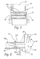
- connection assembly according to the invention is generally designated by the reference numeral 10.
- connection assembly 10 comprises a first box-like connector 11 provided internally with first internal passages 12 for accommodating respective first electrical terminals 13.
- the first connector 11 is substantially L-shaped and has two main parts which form said L-shape: a first part 11a and a second part 11b, which protrudes at right angles to the first part 11a.
- Each first internal passage 12 is also L-shaped and therefore has a first passage portion 12a and a second passage portion 12b which are mutually perpendicular; each first terminal 13 is accommodated in both portions 12a and 12b of the respective first internal passage 12.
- the first connector 11 is provided with means 14 for engaging with the stator, which are described in greater detail hereinafter (in particular, said means interact with portions of a dome made of plastic material, designated by the reference numeral 15 in Figure 1, for covering the stator).
- the engagement means 14 are adapted to arrange the first connector so that the first part 11 a is perpendicular to the axis of the electric motor (a direction which is parallel to said axis is indicated in Figure 1 by a line shown schematically in dots and dashes and designated by the reference letter A); accordingly, the second part 11b of the connector 11 is parallel to said axis.
- the portions 12a and 12b of the first internal passages 12 are open in the direction for engaging the stator assembly in order to be able to insert the respective first terminals 13.
- first connector 11 At the end of the first part 11 a of the first connector 11 there is a coupling cavity 16 for at least one second box-like connector 17 (not shown in cross-section in the figures), which is provided with second internal passages 18 (indicated by an arrow drawn in broken lines) for accommodating corresponding second electrical terminals (one of which is shown schematically by means of broken lines and is designated by the reference numeral 19) for coupling to the first electrical terminals 13.
- the direction of insertion of the second connector 17 is substantially perpendicular to the axis of the electric motor.
- Each first electrical terminal 13 is constituted by a central flat body 20, from a first end of which there protrudes, in a coplanar manner, a flat pin 21 for electrical contact with a respective second electrical terminal 19 and from a second opposite end of which a crimping portion 22 protrudes in a coplanar manner and along a direction which is perpendicular to the extension of the flat pin 21.
- An elastically deformable tooth 23 protrudes from one side of the central flat body 20 along a direction which is incident to the plane of the central flat body 20; the free end of said tooth abuts against a shoulder 24 which is undercut with respect to the direction of extraction of the first terminal 13 from its first passage 13, so as to prevent its extraction; the tooth 23 is constituted by a portion of the central flat body 20 which is wing-shaped, partially cut by blanking and folded so as to rise from the planar arrangement of the central flat body 20.
- the central flat body 20 with the flat pin 21 is accommodated in the first passage portion 12a, while the crimping portion 22 is accommodated in the second passage portion 12b.
- An opening 25 is provided between the cavity 16 and the first passage portion 12a to allow the passage of the flat pin 21 in the cavity 16 and allow connection to the respective second terminal 19.
- the second electrical terminals 19 have a portion for connection to the first terminals 13, which consists of a pair of mutually opposite wings 26 (shown schematically in broken lines in Figure 1) which clamp the flat pins 21 of the first electrical terminals 13 and are connected to the power supply of the motor.
- the lateral guiding walls 16a guide two first mutually opposite sides 21a of the flat pins 21, while the second mutually opposite sides 21b are free in order to allow electrical contact with the second electrical terminals 19.
- the width of the lateral guiding walls 16a is narrower than the distance between the second mutually opposite sides 21b, thus allowing to protrude from the walls 16a and ensure electrical contact with the second electrical terminals 19.
- said walls provide a discontinuous crossmember on the bottom of the cavity 16.
- the engagement means 14 comprise for example a frame 28 provided with two wings 29 which form a C-shape which is adapted to couple by snap action to the stator assembly; the frame 28 protrudes from the face of the first part 11a of the first connector 11 which lies opposite the second part 11b.
- the engagement means 14 also comprise two tabs 30, which protrude from the mutually opposite sides of the second parts 11b of the connector 11 toward the frame 28 and are adapted to be inserted in corresponding receptacles provided in the stator assembly (not shown in the figures).
- the present invention has in fact provided an assembly for connecting the electrical windings of the stator of an electric motor to the respective power supply which is structurally simple and at the same time allows easy assembly of the components of the assembly and considerable stability of the connection during use.
- the materials employed may be any according to requirements and to the state of the art.
Landscapes
- Engineering & Computer Science (AREA)
- Power Engineering (AREA)
- Motor Or Generator Frames (AREA)
- Insulation, Fastening Of Motor, Generator Windings (AREA)
Applications Claiming Priority (1)
| Application Number | Priority Date | Filing Date | Title |
|---|---|---|---|
| IT000395A ITPD20060395A1 (it) | 2006-10-24 | 2006-10-24 | Gruppo di connessione degli avvolgimenti elettrici dello statore di un motore elettrico |
Publications (2)
| Publication Number | Publication Date |
|---|---|
| EP1916756A2 true EP1916756A2 (de) | 2008-04-30 |
| EP1916756A3 EP1916756A3 (de) | 2009-07-29 |
Family
ID=39146921
Family Applications (1)
| Application Number | Title | Priority Date | Filing Date |
|---|---|---|---|
| EP07118734A Withdrawn EP1916756A3 (de) | 2006-10-24 | 2007-10-18 | Anordnung zur Verbindung der elektrischen Statorwicklungen eines elektrischen Motors |
Country Status (3)
| Country | Link |
|---|---|
| US (1) | US20080093941A1 (de) |
| EP (1) | EP1916756A3 (de) |
| IT (1) | ITPD20060395A1 (de) |
Families Citing this family (2)
| Publication number | Priority date | Publication date | Assignee | Title |
|---|---|---|---|---|
| ITPD20060361A1 (it) * | 2006-10-03 | 2008-04-04 | Inarca Spa | Gruppo di connessione di una scheda elettronica di controllo agli avvolgimenti statorici di un motore elettrico per tende a rullo o similari |
| FR3000629A1 (fr) * | 2012-12-27 | 2014-07-04 | Michelin & Cie | Procede de fabrication d'une machine electrique |
Family Cites Families (18)
| Publication number | Priority date | Publication date | Assignee | Title |
|---|---|---|---|---|
| FR1531915A (fr) * | 1966-07-22 | 1968-07-05 | Licentia Gmbh | Raccordement électrique par fiche multipolaire |
| DE2315484C2 (de) * | 1973-03-28 | 1983-03-10 | Siemens AG, 1000 Berlin und 8000 München | Messerleiste |
| US5852338A (en) * | 1997-02-03 | 1998-12-22 | General Electric Company | Dynamoelectric machine and method for manufacturing same |
| DE29601034U1 (de) * | 1995-01-23 | 1996-03-14 | Whitaker Corp | Elektrischer Verbinder für einen Motor |
| DE29623973U1 (de) * | 1995-09-19 | 2000-12-14 | Elco S.P.A., Bergamo | Elektrischer Motor |
| US5770902A (en) * | 1995-11-02 | 1998-06-23 | Globe Motors | Motor termination board |
| US5848918A (en) * | 1997-01-28 | 1998-12-15 | General Signal Corporation | Electrical appliance with novel electrical power connector structure |
| US5873752A (en) * | 1997-12-08 | 1999-02-23 | Joseph Pollak Corporation | Tow socket connector having sealant |
| US6271609B1 (en) * | 1999-03-25 | 2001-08-07 | General Electric Company | Programmable electric motor and method of assembly |
| JP2002125348A (ja) * | 2000-10-12 | 2002-04-26 | Suzuki Motor Corp | 配線接続装置 |
| BR0006484A (pt) * | 2000-12-13 | 2002-08-20 | Empresa Brasileira De Compressores S.A - Embraco | Conector elétrico para motor de compressor hermético |
| DE10162247C1 (de) * | 2001-01-18 | 2002-12-19 | Siemens Ag | Motor-Pumpen-Aggregat, insbesondere Kraftfahrzeug-Bremsvorrichtung |
| JP3571677B2 (ja) * | 2001-09-03 | 2004-09-29 | 本田技研工業株式会社 | ハイブリッド車両用モータの配線構造 |
| JP3971987B2 (ja) * | 2002-06-13 | 2007-09-05 | 日本電産サンキョー株式会社 | モータのステータ構造 |
| JP4089623B2 (ja) * | 2003-06-18 | 2008-05-28 | 株式会社デンソー | 回転電機 |
| JP2005229721A (ja) * | 2004-02-12 | 2005-08-25 | Mitsubishi Electric Corp | 電動パワーステアリング装置用モータ |
| ITPD20060362A1 (it) * | 2006-10-03 | 2008-04-04 | Inarca Spa | ¿gruppo di connessione degli avvolgimenti statorici di un motore elettrico alla rispettiva alimentazione¿ |
| ITPD20060361A1 (it) * | 2006-10-03 | 2008-04-04 | Inarca Spa | Gruppo di connessione di una scheda elettronica di controllo agli avvolgimenti statorici di un motore elettrico per tende a rullo o similari |
-
2006
- 2006-10-24 IT IT000395A patent/ITPD20060395A1/it unknown
-
2007
- 2007-10-18 EP EP07118734A patent/EP1916756A3/de not_active Withdrawn
- 2007-10-19 US US11/907,979 patent/US20080093941A1/en not_active Abandoned
Also Published As
| Publication number | Publication date |
|---|---|
| US20080093941A1 (en) | 2008-04-24 |
| EP1916756A3 (de) | 2009-07-29 |
| ITPD20060395A1 (it) | 2008-04-25 |
Similar Documents
| Publication | Publication Date | Title |
|---|---|---|
| EP2461431B1 (de) | Doppelkontaktträgerklemme | |
| JP5285985B2 (ja) | 雌型端子金具 | |
| EP2337157B1 (de) | Verbinder | |
| EP2930793A1 (de) | Steckverbinder | |
| EP1953872A2 (de) | Elektrischer Buchsenkontakt | |
| TWI523346B (zh) | Electrical connector for circuit board and connector for electrical connector | |
| US11038289B2 (en) | Electrical connector | |
| CN101180773B (zh) | 带有闭锁机构的电连接器 | |
| US7029314B2 (en) | Press-contacting connector | |
| US5034640A (en) | End frame of a small motor with multiple openings for multiple terminal locations | |
| KR20140016817A (ko) | 전기 단자 | |
| US9496629B2 (en) | Structure of socket contact | |
| EP1912288A1 (de) | Anordnung zur Verbindung der Statorwicklungen eines Elektromotors mit dem entsprechenden Netzteil | |
| EP1916745B1 (de) | Anordnung für den Anschluss der Statorwicklungen eines Elektromotors | |
| EP1662616B1 (de) | Verbinderanordnung für elektrische Kabel, für Verbindung zu Verbindern mit Zylinderstifte | |
| EP0641060B1 (de) | Elektrischer Kleinmotor mit Anschlusseinrichtung | |
| EP1115191B1 (de) | Verbindungsanordnung, insbesondere für die Statorwicklung eines Elektromotors | |
| JP4922612B2 (ja) | 電気コネクタ | |
| EP2854227B1 (de) | Anschluss und Steckverbinder damit | |
| US20080093941A1 (en) | Assembly for connecting the electrical stator windings of an electric motor | |
| EP1911129B1 (de) | Elektrischer steckeranschluss | |
| CN211579002U (zh) | 具有并联功能的电线连接器 | |
| CN107230849A (zh) | 压接触头和压接连接器 | |
| JP6622841B2 (ja) | 分岐用接続器、コード付延長用接続器及び配線用差込接続器 | |
| US11894634B2 (en) | Connector |
Legal Events
| Date | Code | Title | Description |
|---|---|---|---|
| PUAI | Public reference made under article 153(3) epc to a published international application that has entered the european phase |
Free format text: ORIGINAL CODE: 0009012 |
|
| AK | Designated contracting states |
Kind code of ref document: A2 Designated state(s): AT BE BG CH CY CZ DE DK EE ES FI FR GB GR HU IE IS IT LI LT LU LV MC MT NL PL PT RO SE SI SK TR |
|
| AX | Request for extension of the european patent |
Extension state: AL BA HR MK RS |
|
| PUAL | Search report despatched |
Free format text: ORIGINAL CODE: 0009013 |
|
| AK | Designated contracting states |
Kind code of ref document: A3 Designated state(s): AT BE BG CH CY CZ DE DK EE ES FI FR GB GR HU IE IS IT LI LT LU LV MC MT NL PL PT RO SE SI SK TR |
|
| AX | Request for extension of the european patent |
Extension state: AL BA HR MK RS |
|
| AKX | Designation fees paid | ||
| REG | Reference to a national code |
Ref country code: DE Ref legal event code: 8566 |
|
| STAA | Information on the status of an ep patent application or granted ep patent |
Free format text: STATUS: THE APPLICATION IS DEEMED TO BE WITHDRAWN |
|
| 18D | Application deemed to be withdrawn |
Effective date: 20100130 |