EP1916936B1 - Appareil de nettoyage en microfibres equipe d'un dispositif de retrait du tampon de nettoyage - Google Patents
Appareil de nettoyage en microfibres equipe d'un dispositif de retrait du tampon de nettoyage Download PDFInfo
- Publication number
- EP1916936B1 EP1916936B1 EP05853530A EP05853530A EP1916936B1 EP 1916936 B1 EP1916936 B1 EP 1916936B1 EP 05853530 A EP05853530 A EP 05853530A EP 05853530 A EP05853530 A EP 05853530A EP 1916936 B1 EP1916936 B1 EP 1916936B1
- Authority
- EP
- European Patent Office
- Prior art keywords
- upper panel
- panel
- cleaning pad
- lower panel
- handle
- Prior art date
- Legal status (The legal status is an assumption and is not a legal conclusion. Google has not performed a legal analysis and makes no representation as to the accuracy of the status listed.)
- Expired - Lifetime
Links
Images






Classifications
-
- A—HUMAN NECESSITIES
- A47—FURNITURE; DOMESTIC ARTICLES OR APPLIANCES; COFFEE MILLS; SPICE MILLS; SUCTION CLEANERS IN GENERAL
- A47L—DOMESTIC WASHING OR CLEANING; SUCTION CLEANERS IN GENERAL
- A47L13/00—Implements for cleaning floors, carpets, furniture, walls, or wall coverings
- A47L13/10—Scrubbing; Scouring; Cleaning; Polishing
- A47L13/20—Mops
- A47L13/24—Frames for mops; Mop heads
- A47L13/254—Plate frames
- A47L13/256—Plate frames for mops made of cloth
-
- A—HUMAN NECESSITIES
- A47—FURNITURE; DOMESTIC ARTICLES OR APPLIANCES; COFFEE MILLS; SPICE MILLS; SUCTION CLEANERS IN GENERAL
- A47L—DOMESTIC WASHING OR CLEANING; SUCTION CLEANERS IN GENERAL
- A47L13/00—Implements for cleaning floors, carpets, furniture, walls, or wall coverings
- A47L13/10—Scrubbing; Scouring; Cleaning; Polishing
- A47L13/20—Mops
- A47L13/24—Frames for mops; Mop heads
- A47L13/254—Plate frames
- A47L13/258—Plate frames of adjustable or foldable type
-
- A—HUMAN NECESSITIES
- A47—FURNITURE; DOMESTIC ARTICLES OR APPLIANCES; COFFEE MILLS; SPICE MILLS; SUCTION CLEANERS IN GENERAL
- A47L—DOMESTIC WASHING OR CLEANING; SUCTION CLEANERS IN GENERAL
- A47L13/00—Implements for cleaning floors, carpets, furniture, walls, or wall coverings
- A47L13/10—Scrubbing; Scouring; Cleaning; Polishing
- A47L13/50—Auxiliary implements
- A47L13/51—Storing of cleaning tools, e.g. containers therefor
-
- A—HUMAN NECESSITIES
- A47—FURNITURE; DOMESTIC ARTICLES OR APPLIANCES; COFFEE MILLS; SPICE MILLS; SUCTION CLEANERS IN GENERAL
- A47L—DOMESTIC WASHING OR CLEANING; SUCTION CLEANERS IN GENERAL
- A47L13/00—Implements for cleaning floors, carpets, furniture, walls, or wall coverings
- A47L13/10—Scrubbing; Scouring; Cleaning; Polishing
- A47L13/50—Auxiliary implements
- A47L13/58—Wringers for scouring pads, mops, or the like, combined with buckets
Definitions
- the present invention pertains to a cleaning apparatus that is comprised of an elongate handle and a cleaning head at one end of the handle.
- the cleaning head is comprised of a pair of panels that can be moved relative to each other.
- the pair of panels support a micro fiber cleaning pad.
- the cleaning pad can be released from the panels after use without manually touching the pad, thereby enabling disposal of a contaminated cleaning pad while reducing the potential for cross contamination to a user of the apparatus.
- the cleaning pad be manually handled when removing the pad from the mop head.
- the task of removing the used cleaning pad from the mop head is, in the least, particularly undesirable, and could be hazardous to the person performing the cleaning task.
- Patent application WO 2004/075707 describes a cleaning device for cleaning toilets having a flushable cleaning head.
- the device is designed so that the cleaning head may be removed without touching the soiled cleaning head.
- the force applied by the ejection member acts perpendicularly to the cleaning head and therefore a reasonably large force is required to separate the cleaning head from the attachment means.
- the micro fiber cleaning apparatus of the present invention overcomes the disadvantages associated with prior art apparatus in that it provides a way of removing a used cleaning pad from the apparatus without requiring manually handling the used cleaning pad.
- This objects are achieved with a cleaning apparatus according to the independent claim 1.
- Preferred embodiments are defined in the dependent claims.
- the apparatus of the invention is described herein in several embodiments, all of which enable removal of a used cleaning pad from the apparatus without requiring manually touching the cleaning pad.
- the concept of the invention is described employed on a floor mop apparatus. However, this should not be interpreted as limiting as the concept of the invention may be equally well suited for use in other equivalent types of apparatus.
- the apparatus of the invention is basically comprised of a mop head, a micro fiber cleaning pad or other equivalent type of cleaning pad that is removably attached to one side of the mop head, and an elongate handle that is attached to the opposite side of the mop head.
- the mop head of the invention has a unique construction that enables a user of the apparatus to remove the cleaning pad from the mop head without manually touching the cleaning pad or the mop head.
- the mop head is basically comprised of an upper panel, a lower panel, and a cleaning pad.
- the cleaning pad is a micro fiber cleaning pad that has a general rectangular configuration.
- the upper panel is positioned on top of the lower panel, and the lower panel is positioned on top of the cleaning pad.
- the upper panel and lower panel are connected together by a hinge connection at one of the edges of each panel. The connection enables the upper panel and the lower panel to be pivoted relative to each other.
- the cleaning pad preferably has a rectangular configuration with opposite top and bottom surfaces.
- the bottom surface of the pad is configured as the pad cleaning surface.
- the top surface of the pad is designed to be removably attached to the mop head of the apparatus.
- the pad top surface has one or more releasable connector members, for example a loop portion or a hook portion of a Velcro® type fastener.
- the lower panel has basically the same size and configuration.as the cleaning pad.
- One or more openings are provided through the lower panel between a top surface of the lower panel and a bottom surface of the lower panel. When the top surface of the cleaning pad is positioned against the bottom surface of the lower panel, the connector members on the cleaning pad top surface are exposed through the lower panel openings.
- the upper panel has basically the same size and configuration as the lower panel.
- the upper panel is connected to the lower panel for movement of the upper panel between first and second positions of the upper panel relative to the lower panel. In the first position, a bottom surface of the upper panel is positioned against the top surface of the lower panel.
- One or more releasable connectors are provided on the bottom surface of the upper panel. The connectors are positioned to extend through the openings of the lower panel when the upper panel is in the first position relative to the lower panel. In this manner, the connector members on the bottom surface of the upper panel extend through the openings of the lower panel and engage with the connector members on the cleaning pad, thereby releasably connecting the cleaning pad to the mop head.
- the connector members on the upper panel are pulled away from the connector members on the cleaning pad. This releases the cleaning pad from the mop head.
- the mop head top panel is provided with projections that extend outwardly from a forward edge of the upper panel and a rearward edge of the upper panel.
- An opening is formed through the center of the upper panel exposing the lower panel beneath the upper panel.
- a handle of the apparatus is connected to the lower panel through the opening in the upper panel.
- a specialized bucket is provided for use with the mop head of the first embodiment.
- the bucket has a top opening with edge portions on opposite sides of the opening that are dimensioned to engage against the projections of the mop head upper panel.
- the mop head is positioned over the top opening of the specialized bucket.
- the projections extending from the opposite forward and rearward edges of the mop head upper panel are engaged against the edge portions of the bucket that surround the bucket opening. This engagement of the upper panel projections with the edge portions of the bucket holds the mop head upper panel stationary over the top opening of the bucket.
- the handle pushes the lower panel downwardly relative to the upper panel into the bucket opening. This causes the upper panel and the lower panel of the mop head to move to their second relative positions. This in turn causes the cleaning pad to separate from the upper panel and fall into the bucket interior. In this manner, the cleaning pad is removed from the apparatus without requiring manually touching the cleaning pad.
- the cleaning pad is removed from the mop head in basically the same manner, without requiring touching the cleaning pad.
- the second and third embodiments of the apparatus include actuators that are mounted on the apparatus handle for sliding movement.
- the actuators are operatively connected to the mop head upper panel.
- the actuator moves the mop head upper panel from its first position relative to the lower panel, to its second position relative to the lower panel. This causes the cleaning pad to be separated from the mop head without requiring manually touching the cleaning pad.
- the handle is connected to the mop head upper panel.
- the upper panel is also provided with an opening at a central portion of the upper panel that exposes the lower panel beneath the upper panel.
- the actuator mounted on the apparatus handle has a projecting prong that is positioned to pass through the opening in the upper panel and engage against the lower panel. The engagement of the prong against the lower panel pushes the lower panel away from the upper panel, and thereby moves the upper panel and lower panel from their first relatives to their second relative positions. This movement of the upper and lower panels causes the cleaning pad to separate away from the mop head without requiring manually touching the cleaning pad.
- All of the embodiments of the apparatus discussed above provide the advantage of enabling a used cleaning pad to be separated from the apparatus without requiring manually touching the cleaning pad.
- micro fiber cleaning apparatus of the present invention is provided in several different embodiments, all of which enable removal of a cleaning pad from the apparatus without requiring manually touching the cleaning pad.
- concept of the invention is described employed on a floor mop apparatus. It should be understood that this environment of the concept of the invention is illustrative only, and is not intended to limit the concept of the invention to use on only floor mops. The concept of the invention may be used on various different types of apparatus that support a cleaning pad in use.
- Each embodiment of the apparatus of the invention to be described is basically comprised of a mop head, a micro fiber cleaning pad or other equivalent type of cleaning pad that is removably attached to the mop head, and an elongate handle that is attached to and extends from the mop head.
- Each of the component parts of the invention, apart from the micro fiber cleaning pad, can be constructed of a plastic material as is conventional in the art.
- the apparatus of the invention is described as comprising a micro fiber cleaning pad, other types of cleaning pads may be used with the invention.
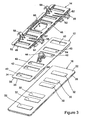
- Figure 1 shows a first embodiment of the apparatus of the invention.
- the apparatus is basically comprised of a mop head that includes a lower panel 12 and an upper panel 14, a cleaning pad 16 that is removably attached to the mop head, and a handle 18 that extends from the mop head.
- These basic component parts of the apparatus are employed in each embodiment of the apparatus to be described.
- the cleaning pad 16 has a rectangular configuration with opposite top 22 and bottom 24 surfaces.
- the pad has a peripheral edge 26 that gives the pad its rectangular configuration and separates the pad top surface 22 from the pad bottom surface 24.
- the bottom surface 24 of the pad is configured as the pad cleaning surface.
- the top surface 22 of the pad is designed to be removably attached to the mop head of the apparatus.
- One or more cleaning pad connector members 32 are mounted on the cleaning pad top surface 22.
- the connector members 32 can be separately secured to the cleaning pad top surface 22 or can be made a part of the cleaning pad.
- the connector members 32 could be a loop portion of a loop and hook releasable fastener, such as a Velcro® type fastener.
- the loop portion of the fastener could be secured to the cleaning pad top surface 22 as the connector member 32, or the material of the cleaning pad itself could function as the loop portion of the fastener.
- the lower panel 12 has basically the same rectangular configuration as the cleaning pad 16.
- the lower panel has opposite top 34 and bottom 36 surfaces, and a rectangular peripheral edge 38 that separates these surfaces.
- One or more openings 42 extend through the lower panel.
- the lower panel openings 42 correspond in shape, dimension, and position with the connector members 32 on the cleaning pad top surface 22.
- the connector members 32 of the cleaning pad 16 are exposed through the lower panel openings 42.
- a handle connector 44 is provided on a central portion of the lower panel top surface 34.
- the handle connector 44 in the preferred embodiment of the invention is a universal type coupling that enables pivoting movement about two perpendicular axes of the connector 44.
- the upper panel 14 has basically the same size and shape configuration as the lower panel 12.
- the upper panel 14 has opposite top 46 and bottom 48 surfaces that are separated by a rectangular peripheral edge 52 of the panel.
- the upper panel bottom surface 48 is provided with a plurality of projecting surface areas 54 that can be seen in Figure 2 .
- the surface areas 54 are the same in number and have basically the same shape as the lower panel openings 42.
- the surface areas 54 are positioned on the upper panel bottom surface 48 in the same spatial arrangement as the openings 42 in the lower panel 12.
- a pair of planar projections 56 project outwardly from one side of the upper panel 12. These projections 56 are basically positioned in the same plane as the upper panel 14.
- a second pair of hooked projections 58 project outwardly from the opposite side of the upper panel 14. As seen in Figure 1 , the hooked projections 58 extend outwardly from the upper panel top surface 46 and then curve outwardly over the upper panel peripheral edge 52, forming the hooked configurations of the projections.
- a connector mechanism in the form of a hinge assembly 62, 64 connects the upper panel 14 to the lower panel 12.
- the connector mechanism 62, 64 enables relative movement between the lower panel 12 and the upper panel 14.
- the hinges of the connector mechanisms 62, 64 connect the lower panel 12 to the upper panel 14 along one edge of each of the two panels.
- the connection enables relative movement between the lower panel 12 and the upper panel 14 where the upper panel moves between first and second positions of the upper panel relative to the lower panel.
- Figure 1 shows the first position of the upper panel 14 relative to the lower panel 12 where the upper panel bottom surface 48 directly opposes the lower panel top surface 34. In this position of the upper panel 14, the projecting surface areas 54 on the upper panel bottom surface 48 extend through the openings 42 in the lower panel 12.
- Figure 2 shows the relative positions of the lower panel 12 and the upper panel 14 where the upper panel has been moved to its second position relative to the lower panel. In the second position of the upper panel 14, the upper panel bottom surface 48 no longer opposes the lower panel top surface 34, and the projecting surface areas 54 on the upper panel 14 have been removed from the openings 42 in the lower panel 12.
- the upper panel 14 is provided with a central opening 66 in the area of the handle connector 44 on the lower panel 12. This enables the handle connector 44 to extend through the upper panel central opening 66 when the upper panel 14 is moved to its first position relative to the lower panel 12 shown in Figure 1 .
- a plurality of upper panel connector members 72 are provided on the projecting surface areas 54 of the upper panel 14.
- the upper panel connector members 72 are releasably connectable to the cleaning pad connector members 32 by being pressed against the cleaning pad connector members.
- the upper panel connector members 72 are removable from the cleaning pad connector members 32 by being pulled from the cleaning pad connector members.
- the upper panel connector members 72 are the other of a loop portion or a hook portion of a Velcro® type fastener from the portion of the fastener employed as the cleaning pad connector members 32.
- Other equivalent types of connector mechanisms may be used.
- the projecting surface areas 54 on the upper panel position the upper panel connector members 72 in engagement with the cleaning pad connector members 32 when the cleaning pad 16 it is positioned adjacent the lower panel bottom surface 36.
- the upper panel connector members 72 are separated from the cleaning pad connector members 32 and the cleaning pad 16 is free to separate from the lower panel 12 and the upper panel 14.
- the handle 18 is connected to the handle connector 44 of the mop head.
- the handle 18 is preferably an elongate rod having opposite proximal 74 and distal 76 ends.
- the handle proximal end 74 is secured to the handle connector 44, and thereby the handle 18 is secured to the lower panel 12 and the upper panel 14.
- the universal connection provided by the handle connector 44 enables the lower panel 12, upper panel 14 and cleaning pad 16 of the mop head to pivot along two perpendicular axes relative to the handle 18 in use of the cleaning apparatus of the invention.
- FIG. 5 shows a specialized bucket that is designed for use with the first embodiment of the apparatus described.
- the bucket 82 has a bottom wall and a plurality of side walls that give the bucket a general cubic configuration.
- the bucket side walls terminate at top edges 84 of the side walls that surround a top opening 86 of the bucket.
- a rod 88 extends across the bucket opening 86.
- the opposite ends of the rod 88 are secured to opposite side wall top edges 84 of the bucket.
- the rod 88 is positioned over the bucket opening 86 to enable insertion of the mop head cleaning pad 16, lower panel 12 and upper panel 14 over the bucket opening 86 between the rod 88 and an adjacent bucket side wall top edge 84.
- the positioning of the rod 88 relative to the bucket top edge 84 enables the mop head of the apparatus to be positioned over the bucket opening 86, with the upper panel planar projections 56 engaging against the side wall top edge 84 and the upper panel hooked projections 58 engaging over the rod 88.
- the cleaning pad 16 is held to the lower panel bottom surface 36 by the releasable engagement between the cleaning pad connector members 32 and the upper panel connector members 72 through the lower panel openings 42.
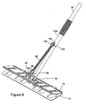
- Figures 6 and 7 show a second embodiment of the apparatus of the invention.
- the cleaning pad 16 used with the second embodiment of the apparatus is the same as that employed with the first embodiment. Therefore, the cleaning pad 16 is not shown in Figures 6 and 7 .
- the lower panel 12 of the mop head is also basically the same as the lower panel 12 employed in the first embodiment of the apparatus of the invention. Therefore, the features of the lower panel 12 shown in Figures 6 and 7 are labeled with the same reference numbers employed in describing the lower panel 12 of the first embodiment of the apparatus.
- the upper panel 14 of the mop head shown in Figures 6 and 7 is also basically the same as the upper panel of the first embodiment of the apparatus. Therefore, features of the upper panel 14 shown in Figures 6 and 7 that are the same as those of the first embodiment of the apparatus are labeled by the same reference numbers.
- the upper panel 14 of Figures 6 and 7 is different from that of the first embodiment in that it does not have the planar projections 56 and the hooked projections 58 of the first embodiment. Instead, the upper panel 14 has a pair of spaced flanges 92 that project upwardly from the upper panel top surface 46. The flanges 92 are spaced from each other and are positioned between the upper panel peripheral edge 52 and the central opening 66 through the upper panel.
- An actuator rod 96 is connected to the actuator connector 94.
- the actuator rod 96 has a length with a proximal end having fork prongs 98 pivotally connected to opposite sides of the actuator connector 94. This connection of the actuator rod 96 to the upper panel 14 by the actuator connector 94 and the upper panel flanges 92 allows the rod 96 to pivot through two mutually perpendicular planes relative to the upper panel 14.
- the opposite distal end of the actuator rod 96 is formed with a pair of distal end prongs 102.
- a tubular actuator sleeve 104 is mounted on the handle 18 for reciprocating sliding movement of the sleeve over the handle.
- a sleeve flange 106 projects outwardly from the sleeve proximal end and is connected by a pivot pin connection to the actuator rod distal end prongs 102. This provides an operative connection between the actuator sleeve 104 and the mop head upper panel 14.
- the operative connection between the actuator sleeve 104 and the mop head upper panel 14 controls movement of the upper panel 14 between its first and second positions relative to the lower panel 12 by reciprocating movements of the actuator sleeve 104 on the handle 18. Movement of the actuator sleeve 104 toward the mop head moves the upper panel 14 to its first position relative to the lower panel 12. Movement of the actuator sleeve 104 away from the mop head moves the upper panel 14 away from the lower panel 12 to its second position relative to the lower panel. Movement of the upper panel 14 from its first position to its second position relative to the lower panel 12 in response to movement of the actuator sleeve 104 on the handle 18 also causes the cleaning pad 16 to separate from the mop head in the same manner as the first embodiment of the apparatus.
- the cleaning pad 16 is released from its connection to the upper panel 14 of the second embodiment of the apparatus, and the cleaning pad 16 falls away from the lower panel 12. In this manner, the cleaning pad 16 can be separated from the mop head of the second embodiment of the apparatus shown in Figures 6 and 7 without requiring manually touching the cleaning pad.
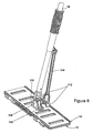
- Figures 8 and 9 show a third embodiment of the apparatus of the invention.
- the third embodiment of the apparatus is basically the same in construction as the second embodiment, except that the length of the upper panel flanges 112 are shorter than those of the second embodiment.
- the length of the actuator rod 114 in the third embodiment is shorter than that of the second embodiment.
- the pair of lower panel flanges 116 that pivotally support the handle connector 118 on the mop head lower panel 12 are also longer than those of the first and second embodiments, whereby the handle connector 116 extends a slightly greater distance through the upper panel central opening 66.
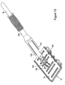
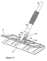
- Figures 10 and 11 show a fourth embodiment of the apparatus of the invention.
- the cleaning pad 16 used with the fourth embodiment of the apparatus is the same as that employed with the first embodiment. Therefore, the cleaning pad 16 is not shown in Figures 10 and 11 .
- the lower panel 12 of the mop head is also basically the same as the lower panel 12 employed in the first embodiment of the apparatus of the invention. Therefore, the features of the lower panel 12 shown in Figures 10 and 11 are labeled with the same reference numbers employed in describing the lower panel 12 of the first embodiment of the apparatus.
- the upper panel 14 of the mop head shown in Figures 10 and 11 is also basically the same as the upper panel of the first embodiment of the apparatus. Therefore, the features of the upper panel 14 shown in Figures 10 and 11 that are the same as those of the first embodiment of the apparatus are labeled by the same reference numbers.
- the lower panel 12 of Figures 10 and 11 is different from that of the first embodiment in that it does not have the handle connector 44 projecting upwardly from the middle of the lower panel top surface 34.
- the lower panel 12 of the fourth embodiment of the apparatus shown in Figures 10 and 11 is basically the same in construction as the lower panel 12 of.the first described embodiment.
- the connector mechanisms 62, 64 connects the lower panel 12 to the upper panel 14 along side edges of each of the two panels.
- the upper panel 14 of Figures 10 and 11 is different of that of the first embodiment in that it does not have the planar projections 56 and the hooked projections 58 of the first embodiment. In addition, the upper panel 14 does not have the central opening 66 of the first embodiment. Instead, the upper panel 14 of the fourth embodiment shown in Figures 10 and 11 is provided with a pair of upper panel flanges 122 that project upwardly from the central portion of the upper panel top surface 46.
- the handle connector 124 is mounted between the pair of flanges 122 for pivoting movement of the connector relative to flanges. As in the first embodiment, the handle connector 124 is a universal connector that allows pivoting movement about two mutually perpendicular axes.
- Fork prongs at the handle proximal end 74 are connected to the handle connector 124.
- the connection provided by the handle connector 124 allows the handle 18 to pivot through two mutually perpendicular planes relative to the mop head.
- a tubular actuator sleeve 128 is mounted on the handle 18 for reciprocating sliding movement of the sleeve over the handle.
- a pair of sleeve prongs 132, 134 project outwardly from the sleeve proximal end. As seen in Figures 10 and 11 , one of the sleeve prongs 132 is longer than the other of the sleeve prongs 134. The longer sleeve prong 132 is positioned on the handle 18 so that it aligns with the upper panel opening 126.
- reciprocation of the actuator sleeve 128 on the handle 18 controls the movement of the upper panel 14 between its first and second positions relative to the lower panel 12.
- the longer actuator sleeve prong 132 will pass through the upper panel opening 126 and engage against the lower panel top surface 34.
- the movement of the actuator sleeve 128 toward the mop head causes the longer actuator sleeve prong 132 to push the lower panel 12 away from the upper panel 14.
Landscapes
- Cleaning Implements For Floors, Carpets, Furniture, Walls, And The Like (AREA)
- Nozzles For Electric Vacuum Cleaners (AREA)
- Cleaning In General (AREA)
- Bidet-Like Cleaning Device And Other Flush Toilet Accessories (AREA)
Claims (10)
- Appareil de nettoyage comprenant :un tampon de nettoyage (16) ayant des surfaces supérieure (22) et inférieure (24) opposées et un bord périphérique (26) qui s'étend autour du tampon de nettoyage et sépare la surface supérieure du tampon de nettoyage de la surface inférieure du tampon de nettoyage, la surface inférieure du tampon de nettoyage étant conçue comme une surface de nettoyage, le tampon de nettoyage (16) ayant un élément de raccordement (32) de tampon de nettoyage sur la surface supérieure (22) du tampon de nettoyage ;un panneau inférieur (12) ayant des surfaces supérieure (34) et inférieure (36) opposées et un bord périphérique (38) qui s'étend autour du panneau inférieur et sépare la surface supérieure du panneau inférieur de la surface inférieure panneau inférieur ;un panneau supérieur (14) ayant des surfaces supérieure (46) et inférieure (48) opposées et un bord périphérique (52) qui s'étend autour du panneau supérieur et sépare la surface supérieure du panneau supérieur de la surface inférieure panneau supérieur :
caractérisé en ce que :un mécanisme de raccordement pivotant (62, 64) raccorde le panneau inférieur (12) et le panneau supérieur (14) et permet un mouvement de pivotement relatif entre le panneau inférieur et le panneau supérieur autour du mécanisme de raccordement (62, 64), ce grâce à quoi le panneau supérieur peut être déplacé entre des première et deuxième positions du panneau supérieur par rapport au panneau inférieur, dans la première position, la surface inférieure du panneau supérieur (48) est à l'opposé de la surface supérieure du panneau inférieur (34) et dans la deuxième position, la surface inférieure du panneau supérieur (48) est pivotée autour du mécanisme de raccordement (62, 64) en s'éloignant de la position opposée à la surface supérieure du panneau inférieur (34) ;le tampon de nettoyage (16), le panneau inférieur (12) et le panneau supérieur (14) sont positionnés de manière relative sur l'appareil en un agencement empilé, le panneau supérieur et le tampon de nettoyage étant positionnés sur des côtés opposés du panneau inférieur lorsque le panneau supérieur est dans la première position ;une ouverture (42) traverse le panneau inférieur (12) et est placée sur le panneau inférieur afin d'exposer l'élément de raccordement (32) de tampon de nettoyage par l'ouverture (42) lorsque la surface supérieure (22) du tampon de nettoyage est positionnée de manière à être accouplée à la surface inférieure (36) du panneau inférieur ; etle panneau supérieur (14) a un élément de raccordement (72) placé sur la surface inférieure (48) du panneau supérieur lorsque l'élément de raccordement (72) du panneau supérieur s'étend par l'ouverture (42) du panneau inférieur et est accouplé et raccordé à l'élément de raccordement (32) de tampon de nettoyage quand la surface supérieure (22) du tampon de nettoyage est positionnée de manière à être accouplée à la surface inférieure (36) du panneau inférieur et quand le panneau supérieur (14) est dans la première position, et est désaccouplé de l'élément de raccordement (32) de tampon de nettoyage quand le panneau supérieur (14) est pivoté autour du mécanisme de raccordement (62, 64) en s'éloignant du panneau inférieur (12) vers la deuxième position. - Appareil selon la revendication 1, comprenant en outre :l'élément de raccordement (32) de tampon de nettoyage et l'élément de raccordement (72) du panneau supérieur qui sont des éléments de raccordement autoagrippants.
- Appareil selon la revendication 1, comprenant en outre :une poignée (18) ayant une longueur allongée avec des extrémités proximale (74) et distale (76) opposées, l'extrémité proximale (74) de la poignée étant raccordée de manière fonctionnelle à l'un des panneaux suivants, à savoir le panneau inférieur (12) ou le panneau supérieur (14) ; etun actionneur (104, 128) monté sur la poignée (18) pour déplacer l'actionneur par rapport à la poignée, l'actionneur (104, 128) fonctionnant avec l'autre des panneaux, à savoir le panneau inférieur (12) ou le panneau supérieur (14) qui n'est pas raccordé de manière fonctionnelle à l'extrémité proximale (74) de la poignée pour provoquer un mouvement relatif du panneau supérieur (14) et du panneau inférieur (12) entre les première etdeuxième positions du panneau supérieur par rapport au panneau inférieur en réponse au mouvement de l'actionneur (104, 128) par rapport à la poignée (18).
- Appareil selon la revendication 3, comprenant en outre :l'actionneur comprenant un manchon tubulaire (104, 128) qui est monté sur la poignée (18) pour obtenir un mouvement glissant de va-et-vient du manchon sur la poignée.
- Appareil selon la revendication 4, comprenant en outre :l'extrémité proximale (74) de la poignée raccordée de manière fonctionnelle au panneau inférieur (12) ; etle manchon tubulaire (104, 128) raccordé de manière fonctionnelle au panneau supérieur (14).
- Appareil selon la revendication 4, comprenant en outre :une tige d'actionneur (96, 114) raccordée entre le manchon tubulaire (104, 128) et le panneau supérieur (14) pour déplacer la tige d'actionneur par rapport au manchon tubulaire et au panneau supérieur.
- Appareil selon la revendication 4, comprenant en outre :l'extrémité proximale (74) de la poignée raccordée de manière fonctionnelle au panneau supérieur (14) ; etle manchon tubulaire (104, 128) ayant une extrémité qui peut s'accoupler avec le panneau inférieur (12) en réponse au mouvement du manchon tubulaire sur la poignée.
- Appareil selon la revendication 1, comprenant en outre :une première saillie (56) faisant saillie vers l'extérieur depuis le panneau supérieur (14) d'un côté du panneau supérieur et une deuxième saillie (58) faisant saillie vers l'extérieur depuis le panneau supérieur (14) de l'autre côté du panneau supérieur ; etun godet (82) ayant une ouverture supérieure (86) et au moins des premier etdeuxième bords (84) adjacents à l'ouverture supérieure du godet, les premier et deuxième bords (84) étant positionnés de manière à s'accoupler avec les première (56) et deuxième (58) saillies sur le panneau supérieur (14) et à supporter le panneau supérieur dans une position adjacente à l'ouverture supérieure du godet (86).
- Appareil selon la revendication 8, comprenant en outre :la première saillie (56) et la deuxième saillie (58) placées sur des côtés opposés du panneau supérieur (14).
- Appareil selon la revendication 8, comprenant en outre :les premier et deuxième bords (84) du godet ayant des positions relatives qui permettent au panneau inférieur (12) de passer entre les premier et deuxième bords (84) et par l'ouverture supérieure du godet (86) lorsque les première (56) et deuxième (58) saillies sur le panneau supérieur (14) sont accouplées avec les premier et deuxième bords (84) respectifs et que le panneau supérieur (14) et le panneau inférieur (12) sont déplacés l'un par rapport à l'autre.
Applications Claiming Priority (2)
| Application Number | Priority Date | Filing Date | Title |
|---|---|---|---|
| US11/189,969 US7530139B2 (en) | 2005-07-26 | 2005-07-26 | Microfiber cleaning apparatus with cleaning pad removal feature |
| PCT/US2005/044630 WO2007018582A2 (fr) | 2005-07-26 | 2005-12-09 | Appareil de nettoyage en microfibres equipe d'un dispositif de retrait du tampon de nettoyage |
Publications (3)
| Publication Number | Publication Date |
|---|---|
| EP1916936A2 EP1916936A2 (fr) | 2008-05-07 |
| EP1916936A4 EP1916936A4 (fr) | 2009-01-14 |
| EP1916936B1 true EP1916936B1 (fr) | 2011-02-09 |
Family
ID=37692693
Family Applications (1)
| Application Number | Title | Priority Date | Filing Date |
|---|---|---|---|
| EP05853530A Expired - Lifetime EP1916936B1 (fr) | 2005-07-26 | 2005-12-09 | Appareil de nettoyage en microfibres equipe d'un dispositif de retrait du tampon de nettoyage |
Country Status (7)
| Country | Link |
|---|---|
| US (1) | US7530139B2 (fr) |
| EP (1) | EP1916936B1 (fr) |
| AT (1) | ATE497716T1 (fr) |
| AU (1) | AU2005335185B2 (fr) |
| CA (1) | CA2618945C (fr) |
| DE (1) | DE602005026338D1 (fr) |
| WO (1) | WO2007018582A2 (fr) |
Families Citing this family (18)
| Publication number | Priority date | Publication date | Assignee | Title |
|---|---|---|---|---|
| US8464391B2 (en) * | 2007-04-03 | 2013-06-18 | Diversey, Inc. | Mop head fixation device and method |
| US8065775B2 (en) * | 2008-10-28 | 2011-11-29 | Michael Alan Cameneti | Mop convenient for the replacement of the consumptive material |
| US20100212099A1 (en) * | 2009-02-23 | 2010-08-26 | Mark Payne | Surface Cleaner |
| US8578540B2 (en) | 2011-01-15 | 2013-11-12 | Bona AB | Vibrating mop head |
| US8438696B2 (en) | 2011-02-16 | 2013-05-14 | Techtronic Floor Care Technology Limited | Surface cleaner including a cleaning pad |
| ITPD20110259A1 (it) * | 2011-08-03 | 2013-02-04 | T T S S R L Tecno Trolley System | Cinematismo di blocco e di sblocco di una base per mop |
| JP5780889B2 (ja) * | 2011-08-31 | 2015-09-16 | 大王製紙株式会社 | 掃除具 |
| USD719712S1 (en) | 2012-09-07 | 2014-12-16 | Diversey, Inc. | Floor maintenance tool |
| USD701361S1 (en) * | 2013-03-06 | 2014-03-18 | Gerald R. Harris | Floor cleaning device |
| GB2511576B (en) * | 2013-03-08 | 2015-10-14 | Vale Mill Rochdale Ltd | Mop |
| US9572472B2 (en) | 2014-09-24 | 2017-02-21 | Geerpres, Inc. | Cleaning device for use with disposable cleaning elements |
| US11154176B2 (en) | 2016-03-16 | 2021-10-26 | Medline Industries, Inc. | Mop with integrated head removal system |
| EP3251575B1 (fr) * | 2016-05-30 | 2024-01-31 | Leifheit Ag | Systeme d'essuyage comprenant un appareil d'essuyage et un conteneur a chiffons |
| DE102017117458A1 (de) | 2017-08-02 | 2019-02-07 | Wolfgang Held | Bodenwischer |
| CN114983304B (zh) * | 2018-12-06 | 2024-08-02 | 西安佳品创意设计有限公司 | 拖把 |
| GB2607022A (en) * | 2021-05-21 | 2022-11-30 | Entaco Ltd | A floor-cleaning arrangement and method |
| USD1050653S1 (en) * | 2024-01-28 | 2024-11-05 | Qing Li | Mop combo |
| USD1050654S1 (en) * | 2024-07-31 | 2024-11-05 | Yantai Mengma Enterprise Management Co., Ltd. | Mop head |
Family Cites Families (23)
| Publication number | Priority date | Publication date | Assignee | Title |
|---|---|---|---|---|
| US3199136A (en) | 1964-09-08 | 1965-08-10 | Philip F George | Mop having disposable sheets |
| US3735441A (en) | 1971-02-22 | 1973-05-29 | Deering Milliken Res Corp | Mop head support tool |
| US3737938A (en) * | 1971-06-24 | 1973-06-12 | American Uniform Co | Combination dust cloth and dust mop |
| US3792505A (en) | 1972-06-21 | 1974-02-19 | American Uniform Co | Combination dust cloth and dust mop |
| US3849725A (en) * | 1972-09-18 | 1974-11-19 | Asahi Optical Co Ltd | Circuit for switching different resistance values corresponding to amount of light measured |
| US3991431A (en) | 1974-09-03 | 1976-11-16 | Minnesota Mining And Manufacturing Company | Mop frame assembly |
| CA1083761A (fr) | 1980-01-18 | 1980-08-19 | Dennis A. Hammond | Fixation pour tete de guipon |
| JPS6037Y2 (ja) * | 1980-01-25 | 1985-01-05 | ダスキンフランチヤイズ株式会社 | モツプ把持具 |
| US4852210A (en) | 1988-02-05 | 1989-08-01 | Krajicek Stephen W | Wet mop with interchangeable scrubbing pad and cloth wipe |
| US5071489A (en) | 1990-01-04 | 1991-12-10 | Dow Brands, Inc. | Floor cleaner using disposable sheets |
| JP3181664B2 (ja) | 1992-03-05 | 2001-07-03 | 株式会社ダスキン | モップ把持具 |
| FR2707859B1 (fr) | 1993-06-29 | 1995-10-06 | Elysees Balzac Financiere | Balai-éponge. |
| US5419015A (en) | 1993-07-06 | 1995-05-30 | Garcia; Teddy | Mop with removable interchangeable work pads |
| US5461749A (en) | 1994-05-31 | 1995-10-31 | Minnesota Mining And Manufacturing Company | Floor mop and cleaning system |
| JP3170443B2 (ja) | 1996-01-09 | 2001-05-28 | ユニ・チャーム株式会社 | 掃除用具 |
| US6098235A (en) | 1999-07-28 | 2000-08-08 | Erwin Tomm | Mop head securement device |
| US6260226B1 (en) | 1999-12-29 | 2001-07-17 | Freudenberg Household Products Lp | Self-wringing flat mop |
| DE10049334C2 (de) * | 2000-10-05 | 2002-07-25 | Vermop Salmon Gmbh | Halter für einen Wischmoppbezug und Wischsystem |
| DE60217568T2 (de) | 2001-03-30 | 2007-11-22 | Filmop S.R.L., Onara Di Tombolo | Mophalter für Mopbezüge mit Taschen |
| US6637065B2 (en) | 2001-08-16 | 2003-10-28 | Blyth S. Biggs | Quick release mop head jaws retainer |
| WO2003032800A1 (fr) | 2001-10-19 | 2003-04-24 | Mopsee Enterprises Ltd. | Balai a laver dote d'un element nettoyant jetable |
| US6659670B1 (en) * | 2002-01-14 | 2003-12-09 | Ams Industries, Inc. | Mop with sprayer |
| GB0304446D0 (en) | 2003-02-27 | 2003-04-02 | Loadstone Ltd | Cleaning device |
-
2005
- 2005-07-26 US US11/189,969 patent/US7530139B2/en active Active
- 2005-12-09 AT AT05853530T patent/ATE497716T1/de not_active IP Right Cessation
- 2005-12-09 AU AU2005335185A patent/AU2005335185B2/en not_active Ceased
- 2005-12-09 WO PCT/US2005/044630 patent/WO2007018582A2/fr not_active Ceased
- 2005-12-09 EP EP05853530A patent/EP1916936B1/fr not_active Expired - Lifetime
- 2005-12-09 CA CA2618945A patent/CA2618945C/fr not_active Expired - Lifetime
- 2005-12-09 DE DE602005026338T patent/DE602005026338D1/de not_active Expired - Lifetime
Also Published As
| Publication number | Publication date |
|---|---|
| WO2007018582A2 (fr) | 2007-02-15 |
| EP1916936A4 (fr) | 2009-01-14 |
| ATE497716T1 (de) | 2011-02-15 |
| US7530139B2 (en) | 2009-05-12 |
| AU2005335185A1 (en) | 2007-02-15 |
| WO2007018582A3 (fr) | 2007-09-13 |
| EP1916936A2 (fr) | 2008-05-07 |
| CA2618945A1 (fr) | 2007-02-15 |
| CA2618945C (fr) | 2010-03-16 |
| DE602005026338D1 (de) | 2011-03-24 |
| US20070022553A1 (en) | 2007-02-01 |
| AU2005335185B2 (en) | 2009-11-12 |
Similar Documents
| Publication | Publication Date | Title |
|---|---|---|
| EP1916936B1 (fr) | Appareil de nettoyage en microfibres equipe d'un dispositif de retrait du tampon de nettoyage | |
| US8640296B2 (en) | Adjustable cleaning head for a cleaning tool | |
| EP2139372B1 (fr) | Dispositif et procédé de fixation d'une tête de balai | |
| HUP0005015A2 (en) | Self-wringing mop | |
| CN101035457A (zh) | 具有擦洗区的拖把 | |
| CN1852672A (zh) | 带有一次性衬垫的清洁装置 | |
| US10188258B2 (en) | Multi-function cleaning tool | |
| KR100595355B1 (ko) | 액세서리 홀더를 포함하는 진공 청소기 | |
| EP2869746B1 (fr) | Dispositif de nettoyage ayant une tête de taille et de forme variables | |
| WO2002071908A3 (fr) | Balai a laver comportant un dispositif d'auto-essorage | |
| WO2011089387A1 (fr) | Balai plat à franges destiné à être utilisé avec des couches de lavage détachables | |
| JPH10314093A (ja) | 掃除具 | |
| EP3349637B1 (fr) | Balai plat | |
| CN114786555B (zh) | 清扫工具 | |
| JP2018198686A (ja) | モップヘッドと操作棒との連結構造およびモップ | |
| CN112716406B (zh) | 清洁工具 | |
| JP3224799B2 (ja) | モップハンドル | |
| EP1672999B1 (fr) | Dispositif de balai a laver a support escamotable | |
| CN120938298A (zh) | 地面清洁工具 | |
| GB2418597A (en) | Manual cleaning apparatus handle, dividable into different lengths | |
| CN212816157U (zh) | 清洁工具 | |
| JPH09140651A (ja) | 掃除具 | |
| JP2007105160A (ja) | 掃除具 | |
| CN120379576A (zh) | 用于清洁元件的保持框架和具有这种保持框架的拖把头以及拖把 | |
| KR20240025391A (ko) | 선택적으로 고정이 가능한 밀대 걸레 |
Legal Events
| Date | Code | Title | Description |
|---|---|---|---|
| PUAI | Public reference made under article 153(3) epc to a published international application that has entered the european phase |
Free format text: ORIGINAL CODE: 0009012 |
|
| 17P | Request for examination filed |
Effective date: 20080131 |
|
| AK | Designated contracting states |
Kind code of ref document: A2 Designated state(s): AT BE BG CH CY CZ DE DK EE ES FI FR GB GR HU IE IS IT LI LT LU LV MC NL PL PT RO SE SI SK TR |
|
| A4 | Supplementary search report drawn up and despatched |
Effective date: 20081215 |
|
| RIC1 | Information provided on ipc code assigned before grant |
Ipc: A47L 13/51 20060101ALI20081209BHEP Ipc: A47L 13/58 20060101ALI20081209BHEP Ipc: A47L 13/20 20060101AFI20070321BHEP Ipc: A47L 13/256 20060101ALI20081209BHEP Ipc: A47L 13/258 20060101ALI20081209BHEP |
|
| 17Q | First examination report despatched |
Effective date: 20090318 |
|
| GRAP | Despatch of communication of intention to grant a patent |
Free format text: ORIGINAL CODE: EPIDOSNIGR1 |
|
| GRAS | Grant fee paid |
Free format text: ORIGINAL CODE: EPIDOSNIGR3 |
|
| GRAA | (expected) grant |
Free format text: ORIGINAL CODE: 0009210 |
|
| AK | Designated contracting states |
Kind code of ref document: B1 Designated state(s): AT BE BG CH CY CZ DE DK EE ES FI FR GB GR HU IE IS IT LI LT LU LV MC NL PL PT RO SE SI SK TR |
|
| REG | Reference to a national code |
Ref country code: GB Ref legal event code: FG4D |
|
| REG | Reference to a national code |
Ref country code: CH Ref legal event code: EP |
|
| REG | Reference to a national code |
Ref country code: IE Ref legal event code: FG4D |
|
| REF | Corresponds to: |
Ref document number: 602005026338 Country of ref document: DE Date of ref document: 20110324 Kind code of ref document: P |
|
| REG | Reference to a national code |
Ref country code: DE Ref legal event code: R096 Ref document number: 602005026338 Country of ref document: DE Effective date: 20110324 |
|
| REG | Reference to a national code |
Ref country code: NL Ref legal event code: VDEP Effective date: 20110209 |
|
| LTIE | Lt: invalidation of european patent or patent extension |
Effective date: 20110209 |
|
| PG25 | Lapsed in a contracting state [announced via postgrant information from national office to epo] |
Ref country code: SE Free format text: LAPSE BECAUSE OF FAILURE TO SUBMIT A TRANSLATION OF THE DESCRIPTION OR TO PAY THE FEE WITHIN THE PRESCRIBED TIME-LIMIT Effective date: 20110209 Ref country code: LT Free format text: LAPSE BECAUSE OF FAILURE TO SUBMIT A TRANSLATION OF THE DESCRIPTION OR TO PAY THE FEE WITHIN THE PRESCRIBED TIME-LIMIT Effective date: 20110209 Ref country code: GR Free format text: LAPSE BECAUSE OF FAILURE TO SUBMIT A TRANSLATION OF THE DESCRIPTION OR TO PAY THE FEE WITHIN THE PRESCRIBED TIME-LIMIT Effective date: 20110510 Ref country code: PT Free format text: LAPSE BECAUSE OF FAILURE TO SUBMIT A TRANSLATION OF THE DESCRIPTION OR TO PAY THE FEE WITHIN THE PRESCRIBED TIME-LIMIT Effective date: 20110609 Ref country code: ES Free format text: LAPSE BECAUSE OF FAILURE TO SUBMIT A TRANSLATION OF THE DESCRIPTION OR TO PAY THE FEE WITHIN THE PRESCRIBED TIME-LIMIT Effective date: 20110520 Ref country code: LV Free format text: LAPSE BECAUSE OF FAILURE TO SUBMIT A TRANSLATION OF THE DESCRIPTION OR TO PAY THE FEE WITHIN THE PRESCRIBED TIME-LIMIT Effective date: 20110209 |
|
| PG25 | Lapsed in a contracting state [announced via postgrant information from national office to epo] |
Ref country code: FI Free format text: LAPSE BECAUSE OF FAILURE TO SUBMIT A TRANSLATION OF THE DESCRIPTION OR TO PAY THE FEE WITHIN THE PRESCRIBED TIME-LIMIT Effective date: 20110209 Ref country code: BE Free format text: LAPSE BECAUSE OF FAILURE TO SUBMIT A TRANSLATION OF THE DESCRIPTION OR TO PAY THE FEE WITHIN THE PRESCRIBED TIME-LIMIT Effective date: 20110209 Ref country code: AT Free format text: LAPSE BECAUSE OF FAILURE TO SUBMIT A TRANSLATION OF THE DESCRIPTION OR TO PAY THE FEE WITHIN THE PRESCRIBED TIME-LIMIT Effective date: 20110209 Ref country code: NL Free format text: LAPSE BECAUSE OF FAILURE TO SUBMIT A TRANSLATION OF THE DESCRIPTION OR TO PAY THE FEE WITHIN THE PRESCRIBED TIME-LIMIT Effective date: 20110209 Ref country code: PL Free format text: LAPSE BECAUSE OF FAILURE TO SUBMIT A TRANSLATION OF THE DESCRIPTION OR TO PAY THE FEE WITHIN THE PRESCRIBED TIME-LIMIT Effective date: 20110209 Ref country code: BG Free format text: LAPSE BECAUSE OF FAILURE TO SUBMIT A TRANSLATION OF THE DESCRIPTION OR TO PAY THE FEE WITHIN THE PRESCRIBED TIME-LIMIT Effective date: 20110509 Ref country code: CY Free format text: LAPSE BECAUSE OF FAILURE TO SUBMIT A TRANSLATION OF THE DESCRIPTION OR TO PAY THE FEE WITHIN THE PRESCRIBED TIME-LIMIT Effective date: 20110209 Ref country code: SI Free format text: LAPSE BECAUSE OF FAILURE TO SUBMIT A TRANSLATION OF THE DESCRIPTION OR TO PAY THE FEE WITHIN THE PRESCRIBED TIME-LIMIT Effective date: 20110209 |
|
| PG25 | Lapsed in a contracting state [announced via postgrant information from national office to epo] |
Ref country code: DK Free format text: LAPSE BECAUSE OF FAILURE TO SUBMIT A TRANSLATION OF THE DESCRIPTION OR TO PAY THE FEE WITHIN THE PRESCRIBED TIME-LIMIT Effective date: 20110209 Ref country code: EE Free format text: LAPSE BECAUSE OF FAILURE TO SUBMIT A TRANSLATION OF THE DESCRIPTION OR TO PAY THE FEE WITHIN THE PRESCRIBED TIME-LIMIT Effective date: 20110209 |
|
| PG25 | Lapsed in a contracting state [announced via postgrant information from national office to epo] |
Ref country code: RO Free format text: LAPSE BECAUSE OF FAILURE TO SUBMIT A TRANSLATION OF THE DESCRIPTION OR TO PAY THE FEE WITHIN THE PRESCRIBED TIME-LIMIT Effective date: 20110209 Ref country code: CZ Free format text: LAPSE BECAUSE OF FAILURE TO SUBMIT A TRANSLATION OF THE DESCRIPTION OR TO PAY THE FEE WITHIN THE PRESCRIBED TIME-LIMIT Effective date: 20110209 Ref country code: SK Free format text: LAPSE BECAUSE OF FAILURE TO SUBMIT A TRANSLATION OF THE DESCRIPTION OR TO PAY THE FEE WITHIN THE PRESCRIBED TIME-LIMIT Effective date: 20110209 |
|
| PLBE | No opposition filed within time limit |
Free format text: ORIGINAL CODE: 0009261 |
|
| STAA | Information on the status of an ep patent application or granted ep patent |
Free format text: STATUS: NO OPPOSITION FILED WITHIN TIME LIMIT |
|
| 26N | No opposition filed |
Effective date: 20111110 |
|
| REG | Reference to a national code |
Ref country code: DE Ref legal event code: R097 Ref document number: 602005026338 Country of ref document: DE Effective date: 20111110 |
|
| PG25 | Lapsed in a contracting state [announced via postgrant information from national office to epo] |
Ref country code: IT Free format text: LAPSE BECAUSE OF FAILURE TO SUBMIT A TRANSLATION OF THE DESCRIPTION OR TO PAY THE FEE WITHIN THE PRESCRIBED TIME-LIMIT Effective date: 20110209 |
|
| PG25 | Lapsed in a contracting state [announced via postgrant information from national office to epo] |
Ref country code: MC Free format text: LAPSE BECAUSE OF NON-PAYMENT OF DUE FEES Effective date: 20111231 |
|
| REG | Reference to a national code |
Ref country code: CH Ref legal event code: PL |
|
| GBPC | Gb: european patent ceased through non-payment of renewal fee |
Effective date: 20111209 |
|
| REG | Reference to a national code |
Ref country code: FR Ref legal event code: ST Effective date: 20120831 |
|
| REG | Reference to a national code |
Ref country code: IE Ref legal event code: MM4A |
|
| REG | Reference to a national code |
Ref country code: DE Ref legal event code: R119 Ref document number: 602005026338 Country of ref document: DE Effective date: 20120703 |
|
| PG25 | Lapsed in a contracting state [announced via postgrant information from national office to epo] |
Ref country code: GB Free format text: LAPSE BECAUSE OF NON-PAYMENT OF DUE FEES Effective date: 20111209 Ref country code: IE Free format text: LAPSE BECAUSE OF NON-PAYMENT OF DUE FEES Effective date: 20111209 Ref country code: DE Free format text: LAPSE BECAUSE OF NON-PAYMENT OF DUE FEES Effective date: 20120703 Ref country code: LI Free format text: LAPSE BECAUSE OF NON-PAYMENT OF DUE FEES Effective date: 20111231 Ref country code: CH Free format text: LAPSE BECAUSE OF NON-PAYMENT OF DUE FEES Effective date: 20111231 |
|
| PG25 | Lapsed in a contracting state [announced via postgrant information from national office to epo] |
Ref country code: FR Free format text: LAPSE BECAUSE OF NON-PAYMENT OF DUE FEES Effective date: 20120102 |
|
| PG25 | Lapsed in a contracting state [announced via postgrant information from national office to epo] |
Ref country code: LU Free format text: LAPSE BECAUSE OF NON-PAYMENT OF DUE FEES Effective date: 20111209 |
|
| PG25 | Lapsed in a contracting state [announced via postgrant information from national office to epo] |
Ref country code: IS Free format text: LAPSE BECAUSE OF FAILURE TO SUBMIT A TRANSLATION OF THE DESCRIPTION OR TO PAY THE FEE WITHIN THE PRESCRIBED TIME-LIMIT Effective date: 20110209 |
|
| PG25 | Lapsed in a contracting state [announced via postgrant information from national office to epo] |
Ref country code: TR Free format text: LAPSE BECAUSE OF FAILURE TO SUBMIT A TRANSLATION OF THE DESCRIPTION OR TO PAY THE FEE WITHIN THE PRESCRIBED TIME-LIMIT Effective date: 20110209 |
|
| PG25 | Lapsed in a contracting state [announced via postgrant information from national office to epo] |
Ref country code: HU Free format text: LAPSE BECAUSE OF FAILURE TO SUBMIT A TRANSLATION OF THE DESCRIPTION OR TO PAY THE FEE WITHIN THE PRESCRIBED TIME-LIMIT Effective date: 20110209 |