EP1917870B1 - Maschine zur Herstellung von Filtern für Tabakprodukte - Google Patents
Maschine zur Herstellung von Filtern für Tabakprodukte Download PDFInfo
- Publication number
- EP1917870B1 EP1917870B1 EP20070119418 EP07119418A EP1917870B1 EP 1917870 B1 EP1917870 B1 EP 1917870B1 EP 20070119418 EP20070119418 EP 20070119418 EP 07119418 A EP07119418 A EP 07119418A EP 1917870 B1 EP1917870 B1 EP 1917870B1
- Authority
- EP
- European Patent Office
- Prior art keywords
- section
- machine
- duct
- bundle
- flow
- Prior art date
- Legal status (The legal status is an assumption and is not a legal conclusion. Google has not performed a legal analysis and makes no representation as to the accuracy of the status listed.)
- Not-in-force
Links
Images


Classifications
-
- A—HUMAN NECESSITIES
- A24—TOBACCO; CIGARS; CIGARETTES; SIMULATED SMOKING DEVICES; SMOKERS' REQUISITES
- A24D—CIGARS; CIGARETTES; TOBACCO SMOKE FILTERS; MOUTHPIECES OF CIGARS OR CIGARETTES; MANUFACTURE OF TOBACCO SMOKE FILTERS OR MOUTHPIECES
- A24D3/00—Tobacco smoke filters, e.g. filter tips or filtering inserts; Filters specially adapted for simulated smoking devices; Mouthpieces of cigars or cigarettes
- A24D3/02—Manufacture of tobacco smoke filters
- A24D3/0229—Filter rod forming processes
- A24D3/0233—Filter rod forming processes by means of a garniture
-
- A—HUMAN NECESSITIES
- A24—TOBACCO; CIGARS; CIGARETTES; SIMULATED SMOKING DEVICES; SMOKERS' REQUISITES
- A24D—CIGARS; CIGARETTES; TOBACCO SMOKE FILTERS; MOUTHPIECES OF CIGARS OR CIGARETTES; MANUFACTURE OF TOBACCO SMOKE FILTERS OR MOUTHPIECES
- A24D3/00—Tobacco smoke filters, e.g. filter tips or filtering inserts; Filters specially adapted for simulated smoking devices; Mouthpieces of cigars or cigarettes
- A24D3/02—Manufacture of tobacco smoke filters
- A24D3/0204—Preliminary operations before the filter rod forming process, e.g. crimping, blooming
Definitions
- the present invention relates to a machine for manufacturing filters applicable to tobacco products, and in particular to cigarettes.
- the manufacture of cigarette filters generally involves processing a continuous stream of filter material, such as cellulose acetate, which is drawn from a compacted bale.
- the continuous stream of filter material consists in a high number (thousands) of continuous filaments.
- Prior art manufacturing methods include a step of feeding the stream along a predetermined path through processing stations, where it is first stretched lengthwise and crosswise, and then wetted with chemical additives, typically triacetin.
- the filter material is gathered into a continuous rope or bundle of cylindrical appearance by respective shaping means.
- the shaping means appear as a funnel-like duct into which the continuous stream is introduced, carried forward by a flow of air, its transverse dimension reducing gradually to the point that the filaments are drawn into a rope, or bundle, presenting a cross section substantially the same as that of a cigarette.
- the bundle passes through a further processing station where it is wrapped by degrees in a continuous strip of paper material, forming a continuous filter rod that will then be divided up into single plugs by a rotary cutter device.
- the annular passage is inclined relative to the feed direction of the continuous bundle, in such a manner that the pressurized air admitted via the passage will enter the duct and invest the outer surface of the bundle of filter material, assisting its progress toward the outlet of the duct, as for example described in documents EP 546519 and EP 594054 .
- the air enters the annular passage at one or more localized points, with the result that the flow investing the continuous bundle as it forms internally of the duct is not homogeneous.
- the bundle is subject to asymmetrical thrust components that will translate into poor production stability, that is to say inconsistencies in the filtration properties presented by a given continuous bundle.
- the object of the present invention is primarily to provide a machine for manufacturing filters applicable to tobacco products, such as will be unaffected by the drawback mentioned above.
- the object of the invention is to provide a machine manufacturing filters for tobacco products that will convey the continuous bundle of filter material in a uniform manner.
- a further object of the present invention is to provide a machine manufacturing filters for tobacco products, having the attributes needed to ensure good production stability.
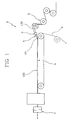
- numeral 1 denotes a machine for manufacturing filters applicable to tobacco products, embodied in accordance with the present invention.
- the machine 1 comprises feed means 2 supplying a continuous stream 100 of filter material, a duct 3 along which the continuous stream 100 of filter material is directed and formed into a cylindrical bundle 101 (illustrated partially in figure 3 ), a nozzle 4 at the end of the duct 3, from which the bundle emerges as a continuous rod 102, a garniture section 5 along which the continuous rod 102 is enveloped in a strip 6 of paper plugwrap material, and means 7 by which the wrapped rod is cut into single filter plugs, also feed means 8, illustrated in figures 2 , 3 and 4 , supplying a flow of air by which the bundle 101 forming within the duct 3 is subjected to an axial pushing force.
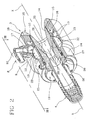
- the feed means 8 comprise an inlet port 9 admitting the flow of air, associated with a fitting 10 for connection to a compressed air supply line (not illustrated), and an annular passage 11 located between the air inlet 9 and the bore of the duct 3.
- the annular passage affords an air gap of which the flow section is significantly small compared to the length of the selfsame gap as measured along the flow-through direction.
- Air is conveyed from the inlet port 9 toward the duct 3 in a direction substantially orthogonal, or ideally inclined, relative to the feed direction X followed by the bundle 101 along the duct 3.
- the air inlet port 9 is not of annular geometry like the passage 11, but located at a single point on the periphery of the duct 3, or in any event a limited number of points (see figures 2 to 4 ).
- the feed means 8 supplying the flow of air comprise equalizing means 12, preferably of a type designed to induce a pressure drop, located between the inlet port 9 and the annular passage 11 and serving to ensure the supply of a uniform flow of air into the passage 11.
- the continuous bundle 101 forming within the duct 3 is invested by a homogeneous flow of air such as will assist its progress along the selfsame duct 3, thus favouring a good stability of production (with filtration properties maintained constant along the full length of the bundle).
- the equalizing means 12 comprise an expansion chamber 13 located between the inlet port 9 admitting the flow of compressed air, and the annular passage 11.
- the expansion chamber 13 is annular in shape and fully encircles the innermost part of the duct 3, that is to say the tube 14 internally of which the continuous bundle 101 advances.
- the expansion chamber 13 is also connected to a distribution chamber 15, presenting a wall 16, by way of which the flow of air is directed into the annular passage 11.
- the compressed air inlet port 9 communicates directly with the expansion chamber 13, whilst the distribution chamber 15 is located downstream of the expansion chamber 13, presenting an annular configuration and encircling the tube 14 in like manner to the upstream chamber 13.
- the holes 17 serve to induce further pressure losses in the flow of air, the effect of which being to equalize the distribution of both the velocity component and the pressure component in the flow directed through the annular passage 11 and onto the continuous bundle 101.
- the annular passage 11 is inclined in relation to the feed direction X followed by the bundle 101 along the duct 3, and in particular, inclined at an angle such that the flow of air will be directed as tangentially as possible onto the bundle 101.
- the annular passage 11 is created between two half sections 18 and 19 making up the duct 3.
- the first half-section 18 of the duct 3 presents a cavity 20 establishing a first segment of the aforementioned tube 14 through which the bundle 101 is directed.
- the cavity 20 is of substantially convergent funnel-like geometry, and thus easily associated with the feed means 2 from which the continuous stream 100 of filter material is received.
- a cavity 20 of the type in question could be embodied as a succession of rectilinear conical duct portions joined suitably one to the next, or alternatively, with a continuous profile of which the geometry appears substantially parabolic or comparable to cubic splines or splines of higher order.
- the second half-section 19 of the duct 3 is associated stably with the first half-section 18 and translatable relative thereto along an axis parallel to the feed direction X followed by the cylindrical bundle 101 forming in the duct, as will be made clearer in due course.
- the first and second half-sections 18 and 19 present respective annular surfaces denoted 21 and 22, breasted one with another and inclined relative to the aforementioned feed direction X of bundle 101.
- the two annular surfaces 21 and 22 in question combine operationally to delimit a main portion of the passage 11.
- the distance separating the two inclined annular surfaces 21 and 22 can be adjusted by translating the second half-section 19 relative to the first half-section 18, so as to widen or narrow the flow section afforded by the passage 11: see figure 3 , for example, where the flow section of the passage 11 is at minimum, or figure 4 , where the flow section is at maximum.
- the second half-section 19 is aligned and associated coaxially with the first half-section 18 by way of suitable coupling means, which in the preferred embodiment illustrated are embodied as respective screw threads 23.
- this same second half-section 19 can be distanced from the first half-section 18, and the flow section of the passage 11 widened.
- the flow equalizing means 12, and more precisely the expansion chamber 13 and the distribution chamber 15, are associated permanently with the first half-section 18 and therefore remain stationary during the movement by which the flow section of the annular passage 11 is adjusted.
- the second half-section 19 is located downstream of the first half-section 18, as already mentioned, and coupled directly to the nozzle 4 from which the bundle 101 emerges.
- the first half-section 18 presents a sleeve 24 in which the second half-section 19 is insertable and on which an aforementioned coupling thread 23 is formed.
- the outer surface of the sleeve 24 presents a set screw 25 passing through the sleeve 24 wall, by which the second half-section 19 is engaged and locked in the selected angular position.
- the terminal portion of the annular passage 11 is incorporated directly into a portion of the aforementioned tube 14 coinciding with a substantially cylindrical cavity 27 afforded by the second half-section 19.
- the portion of the tube 14 afforded by the second half-section 19 presents a plurality of grooves 28 extending parallel to the feed direction X of the bundle 101, also parallel one with another and distributed circumferentially around the tube 14.
- the grooves 28 will ensure that the flow of air continues to invest the entire surface of the bundle 101 and thus cause the material to advance correctly.
- the grooves 28 also function actively as flow guides.
- the equalizing means ensure that the pressure and velocity of the air flowing into the annular passage and destined to invest the bundle gathering in the duct will be, to all intents and purposes, uniformly distributed around the entire annular periphery of the passage inlet section.
- the function of the expansion chamber and the distribution chamber is to handle the flow of air from the inlet port to the annular passage in such a way that it will be rendered uniform and without appreciable variations or imbalances in pressure and velocity.
- any asymmetrical distribution of pressure and velocity components in the air flow, considered in relation to the inlet section of the annular passage, is significantly attenuated, so that the flow of air will present substantially the same pressure and velocity characteristics when passing both through the portion of the passage located in close proximity to the inlet port and through the portion of the passage located farthest from the inlet port.
Landscapes
- Cigarettes, Filters, And Manufacturing Of Filters (AREA)
- Manufacturing Of Cigar And Cigarette Tobacco (AREA)
Claims (10)
- Maschine zur Herstellung von Filtern für Tabakprodukte, Folgendes beinhaltend:- Zufuhrmittel (2) zum Zuführen zumindest eines Endlosstrangs (100) aus Filtermaterial;- einen Kanal (3), entlang dem der Endlosstrang (100) geleitet und zu einem zylindrischen Tau oder Bündel (101) aus solchem Filtermaterial zusammengeführt wird;- eine Düse (4) an dem Ende des Kanals (3) aus der das gebündelte Filtermaterial als Endlosstange (102) austritt,- Schneidmittel (7), durch welche die Stange (102) in einzelne Filterstopfen zerteilt wird;- Zufuhrmittel (8) zum Zuführen eines Luftstromes, durch den das zusammenzuführende Bündel (101) axial entlang dem Kanal (3) zwangsgeführt wird, beinhaltend eine Einlassöffnung (9) für den Einlass des Luftstroms und einen ringförmigen Durchgang (11), der zwischen der Einlassöffnung (9) und der Bohrung des Kanals (3) angeordnet ist, wobei die Zufuhrmittel (8) zum Zuführen eines Luftstromes eine Expansionskammer (13) beinhalten, die als ringförmige Kammer ausgebildet ist und in direkte Verbindung mit der Einlassöffnung (9) für den Luftstrom gesetzt ist;- eine Verteilungskammer ( 15), die zwischen der Expansionskammer (13) und dem ringförmigen Durchgang (11) angeordnet ist;
dadurch gekennzeichnet, dass die Verteilungskammer (15) ringförmig ist und eine Wand (16) beinhaltet, die mit mehreren Löchern (17) versehen ist, die direkt auf die Expansionskammer (13) weisen und zum Ausgleichen des in die Verteilungskammer (15) eintretenden Luftstroms dienen. - Maschine nach Anspruch 1, worin die Verteilungskammer (15) in direkte Verbindung mit dem ringförmigen Durchgang (11) gesetzt ist.
- Maschine nach Anspruch 1, worin der Kanal (3) einen ersten Halbabschnitt (18) und einen zweiten Halbabschnitt (19) beinhaltet, die koaxial zueinander und ineinander eingreifend angeordnet sind und jeweils entsprechende ringförmige Oberflächen (21, 22) aufweisen, die relativ zu einer von dem zusammenzuführenden Bündel (101) verfolgten Vorschubrichtung (X) schräg geneigt sind und zusammenwirken, um zumindest einen Teil des ringförmigen Durchgangs (11) zu bilden.
- Maschine nach Anspruch 3, worin der zweite Halbabschnitt (19) mehrere Rillen (28) beinhaltet, die an einer vom Kanal (3) aufgewiesenen Wand eines Rohres (14) ausgebildet sind, durch das und entlang dem das Bündel (101) geleitet und zusammengeführt wird.
- Maschine nach Anspruch 3, worin der zweite Halbabschnitt (19) in der Lage ist, eine Bewegung relativ zu dem ersten Halbabschnitt (18) in einer Richtung parallel zu der von dem Bündel (101) verfolgten Vorschubrichtung (X) auszuführen, um den von dem ringförmigen Durchgang (11) aufgewiesenen Strömungsquerschnitt zu vergrößern oder zu verringern.
- Maschine nach Anspruch 5, worin Strömungsausgleichsmittel (12) einteilig mit dem ersten Halbabschnitt (18) ausgeführt sind.
- Maschine nach Anspruch 6, worin der erste Halbabschnitt (18) einen Hohlraum (20) beinhaltet, der eine im Wesentlichen konvergierende trichterartige Gestalt aufweist, durch den und entlang dem das Bündel (101) geleitet und zusammengeführt wird, und der mit einem Ende zu den Zufuhrmitteln (2) für das Zuführen des Filtermaterials und mit dem gegenüberliegenden Ende zu der Düse (4) hin ausgerichtet ist.
- Maschine nach Anspruch 7, worin der Hohlraum (20) als eine Aufeinanderfolge geradliniger, konischer Kanalabschnitte erscheint, die jeweils einer mit dem nachfolgenden verbunden sind.
- Maschine nach Anspruch 7, worin der Hohlraum (20) ein kontinuierliches und stromlinienförmiges Profil mit im Wesentlichen parabolischer Geometrie aufweist, beziehungsweise vergleichbar ist mit kubischen Splines oder Splines höheren Grades.
- Maschine nach Anspruch 5, worin der zweite Halbabschnitt (19) mittels einer Schraubverbindung (23) beweglich mit dem ersten Halbabschnitt (18) verbunden ist.
Applications Claiming Priority (1)
| Application Number | Priority Date | Filing Date | Title |
|---|---|---|---|
| ITBO20060749 ITBO20060749A1 (it) | 2006-10-31 | 2006-10-31 | Macchina confezionatrice di filtri per articoli da fumo |
Publications (3)
| Publication Number | Publication Date |
|---|---|
| EP1917870A2 EP1917870A2 (de) | 2008-05-07 |
| EP1917870A3 EP1917870A3 (de) | 2009-03-11 |
| EP1917870B1 true EP1917870B1 (de) | 2011-01-26 |
Family
ID=39099854
Family Applications (1)
| Application Number | Title | Priority Date | Filing Date |
|---|---|---|---|
| EP20070119418 Not-in-force EP1917870B1 (de) | 2006-10-31 | 2007-10-26 | Maschine zur Herstellung von Filtern für Tabakprodukte |
Country Status (4)
| Country | Link |
|---|---|
| EP (1) | EP1917870B1 (de) |
| CN (1) | CN101171977B (de) |
| DE (1) | DE602007012189D1 (de) |
| IT (1) | ITBO20060749A1 (de) |
Cited By (3)
| Publication number | Priority date | Publication date | Assignee | Title |
|---|---|---|---|---|
| EP2982253A1 (de) | 2014-08-08 | 2016-02-10 | HAUNI Maschinenbau AG | Transportdüse für eine vorrichtung zur herstellung von filterstäben für die tabakverarbeitende industrie und vorrichtung zur herstellung von filterstäben für die tabakverarbeitende industrie |
| RU2646018C2 (ru) * | 2013-02-15 | 2018-02-28 | Интернэшнл Тобакко Машинери Поланд Сп. з о.о. | Способ, механизм и устройство для моментального сжатия материала фильтра |
| US12479184B2 (en) | 2022-11-11 | 2025-11-25 | Boegli-Gravures Sa | Method and tool for embossing of biodegradable paper to fabricate cigarette filters |
Families Citing this family (9)
| Publication number | Priority date | Publication date | Assignee | Title |
|---|---|---|---|---|
| GB0905211D0 (en) | 2009-03-26 | 2009-05-13 | British American Tobacco Co | Guide nozzle for use with filter rod manufacturing apparatus |
| ITBO20100637A1 (it) * | 2010-10-22 | 2012-04-23 | Gd Spa | Macchina per la produzione di filtri per sigarette. |
| ITBO20100693A1 (it) * | 2010-11-19 | 2012-05-20 | Montrade S R L | Metodo e dispositivo per l'avanzamento pneumatico di un cordone continuo di materiale filtrante per articoli da fumo |
| ITBO20110206A1 (it) | 2011-04-18 | 2012-10-19 | Gd Spa | Gruppo compattatore per una macchina per la produzione di filtri per sigarette. |
| CN102715653B (zh) * | 2012-07-03 | 2013-11-13 | 云南玉溪卷烟厂滤嘴棒分厂 | 滤棒成型机导丝喇叭咀 |
| ITBO20130314A1 (it) * | 2013-06-21 | 2014-12-22 | Gd Spa | Macchina per la produzione di filtri per sigarette |
| CN103783665B (zh) * | 2014-03-01 | 2015-09-23 | 南通烟滤嘴有限责任公司 | 两级风力捕丝器 |
| GB201715922D0 (en) * | 2017-09-29 | 2017-11-15 | British American Tobacco Investments Ltd | A filter unit for a smoking article |
| IT201700117804A1 (it) | 2017-10-18 | 2019-04-18 | Gd Spa | Unità di crimpatura |
Family Cites Families (4)
| Publication number | Priority date | Publication date | Assignee | Title |
|---|---|---|---|---|
| US3050430A (en) * | 1959-11-12 | 1962-08-21 | Eastman Kodak Co | Jet and method of filter manufacture |
| US3173188A (en) * | 1961-11-03 | 1965-03-16 | Eastman Kodak Co | Tobacco smoke filter formation |
| US5282779A (en) * | 1991-12-09 | 1994-02-01 | Mitsubishi Rayon Company Ltd. | Air jet for producing filter plug for cigarette |
| US5331976A (en) | 1992-10-21 | 1994-07-26 | Hoechst Celanese Corporation | Transport jet adapter |
-
2006
- 2006-10-31 IT ITBO20060749 patent/ITBO20060749A1/it unknown
-
2007
- 2007-10-26 EP EP20070119418 patent/EP1917870B1/de not_active Not-in-force
- 2007-10-26 DE DE200760012189 patent/DE602007012189D1/de active Active
- 2007-10-30 CN CN2007101849966A patent/CN101171977B/zh not_active Expired - Fee Related
Cited By (4)
| Publication number | Priority date | Publication date | Assignee | Title |
|---|---|---|---|---|
| RU2646018C2 (ru) * | 2013-02-15 | 2018-02-28 | Интернэшнл Тобакко Машинери Поланд Сп. з о.о. | Способ, механизм и устройство для моментального сжатия материала фильтра |
| EP2982253A1 (de) | 2014-08-08 | 2016-02-10 | HAUNI Maschinenbau AG | Transportdüse für eine vorrichtung zur herstellung von filterstäben für die tabakverarbeitende industrie und vorrichtung zur herstellung von filterstäben für die tabakverarbeitende industrie |
| DE102014011542A1 (de) | 2014-08-08 | 2016-02-11 | Hauni Maschinenbau Ag | Transportdüse für eine Vorrichtung zur Herstellung von Filterstäben für die Tabakverarbeitende Industrie und Vorrichtung zur Herstellung von Filterstäben für die Tabakverarbeitende Industrie |
| US12479184B2 (en) | 2022-11-11 | 2025-11-25 | Boegli-Gravures Sa | Method and tool for embossing of biodegradable paper to fabricate cigarette filters |
Also Published As
| Publication number | Publication date |
|---|---|
| ITBO20060749A1 (it) | 2007-01-30 |
| EP1917870A3 (de) | 2009-03-11 |
| EP1917870A2 (de) | 2008-05-07 |
| CN101171977A (zh) | 2008-05-07 |
| CN101171977B (zh) | 2011-08-10 |
| DE602007012189D1 (de) | 2011-03-10 |
Similar Documents
| Publication | Publication Date | Title |
|---|---|---|
| EP1917870B1 (de) | Maschine zur Herstellung von Filtern für Tabakprodukte | |
| US5387285A (en) | Apparatus for injecting a fluid into filter tow | |
| EP0128031B1 (de) | Herstellung von Tabakrauchfiltern | |
| CN102892314B (zh) | 用于吸烟物品的棒以及用于制造该棒的方法和装置 | |
| US5331976A (en) | Transport jet adapter | |
| US20150164133A1 (en) | Filter for a Smoking Article | |
| JP4584371B2 (ja) | フイルタ用トウストリップを処理するための方法および装置 | |
| EP2679106B1 (de) | Herstellung von zigarettenfiltern und herstellungsverfahren für zigarettenfilter | |
| US4768526A (en) | Tobacco smoke filters | |
| KR102095713B1 (ko) | 세그먼트형 필터들을 가지는 끽연류들을 조립하기 위한 끽연류 조립 기계 | |
| US4770193A (en) | Manufacture of tobacco smoke filters | |
| US5203757A (en) | Method and apparatus for producing tobacco smoke filter rods | |
| CA1324940C (en) | Method and apparatus for producing tobacco-smoke-filter rods | |
| CN101584498B (zh) | 用于将添加剂加入到一用于抽吸产品的生产而设置的并且已经形成圆形的纤维束中的装置 | |
| JP2018521644A (ja) | 伸縮式同軸状フィルタ・タバコ、および関連する生産方法、フィルタロッド生産機械、ならびにフィルタチップ取り付け機械 | |
| EP2633769A1 (de) | Zigarettenfilterherstellungsmaschine | |
| JP2012239437A (ja) | トウトランスポートジェット | |
| CN107734980B (zh) | 用于处理刚性包装纸幅材料的改进的滤嘴条成型机 | |
| WO2011036452A1 (en) | Tow cutter | |
| WO2014125096A1 (en) | System and method for supplying filter tow and plug wrap to a rod formation stage of a filter rod manufacturing system | |
| CA1229282A (en) | Manufacture of tobacco smoke filters | |
| CN111920088B (zh) | 烟草制品的过滤部件、以及用于制造过滤部件的方法及设备 | |
| EP4731025A1 (de) | Verfahren zur herstellung von tabakstäben und maschine zur herstellung von tabakstäben mit einer vorrichtung zum pneumatischen herausziehen eines kontinuierlichen stabes aus einer formungseinheit | |
| HK1204435B (en) | Rod for a smoking article and method and apparatus for manufacture | |
| HK1180192B (en) | Rod for a smoking article and method and apparatus for manufacture |
Legal Events
| Date | Code | Title | Description |
|---|---|---|---|
| PUAI | Public reference made under article 153(3) epc to a published international application that has entered the european phase |
Free format text: ORIGINAL CODE: 0009012 |
|
| AK | Designated contracting states |
Kind code of ref document: A2 Designated state(s): AT BE BG CH CY CZ DE DK EE ES FI FR GB GR HU IE IS IT LI LT LU LV MC MT NL PL PT RO SE SI SK TR |
|
| AX | Request for extension of the european patent |
Extension state: AL BA HR MK RS |
|
| PUAL | Search report despatched |
Free format text: ORIGINAL CODE: 0009013 |
|
| AK | Designated contracting states |
Kind code of ref document: A3 Designated state(s): AT BE BG CH CY CZ DE DK EE ES FI FR GB GR HU IE IS IT LI LT LU LV MC MT NL PL PT RO SE SI SK TR |
|
| AX | Request for extension of the european patent |
Extension state: AL BA HR MK RS |
|
| 17P | Request for examination filed |
Effective date: 20090427 |
|
| AKX | Designation fees paid |
Designated state(s): CH DE FR GB LI |
|
| GRAP | Despatch of communication of intention to grant a patent |
Free format text: ORIGINAL CODE: EPIDOSNIGR1 |
|
| GRAS | Grant fee paid |
Free format text: ORIGINAL CODE: EPIDOSNIGR3 |
|
| GRAA | (expected) grant |
Free format text: ORIGINAL CODE: 0009210 |
|
| AK | Designated contracting states |
Kind code of ref document: B1 Designated state(s): CH DE FR GB LI |
|
| REG | Reference to a national code |
Ref country code: GB Ref legal event code: FG4D |
|
| REG | Reference to a national code |
Ref country code: CH Ref legal event code: EP |
|
| REF | Corresponds to: |
Ref document number: 602007012189 Country of ref document: DE Date of ref document: 20110310 Kind code of ref document: P |
|
| REG | Reference to a national code |
Ref country code: DE Ref legal event code: R096 Ref document number: 602007012189 Country of ref document: DE Effective date: 20110310 |
|
| REG | Reference to a national code |
Ref country code: CH Ref legal event code: NV Representative=s name: BUGNION S.A. |
|
| PLBE | No opposition filed within time limit |
Free format text: ORIGINAL CODE: 0009261 |
|
| STAA | Information on the status of an ep patent application or granted ep patent |
Free format text: STATUS: NO OPPOSITION FILED WITHIN TIME LIMIT |
|
| 26N | No opposition filed |
Effective date: 20111027 |
|
| REG | Reference to a national code |
Ref country code: DE Ref legal event code: R097 Ref document number: 602007012189 Country of ref document: DE Effective date: 20111027 |
|
| REG | Reference to a national code |
Ref country code: CH Ref legal event code: PL |
|
| PG25 | Lapsed in a contracting state [announced via postgrant information from national office to epo] |
Ref country code: CH Free format text: LAPSE BECAUSE OF NON-PAYMENT OF DUE FEES Effective date: 20111031 Ref country code: LI Free format text: LAPSE BECAUSE OF NON-PAYMENT OF DUE FEES Effective date: 20111031 |
|
| REG | Reference to a national code |
Ref country code: FR Ref legal event code: PLFP Year of fee payment: 9 |
|
| REG | Reference to a national code |
Ref country code: FR Ref legal event code: PLFP Year of fee payment: 10 |
|
| PGFP | Annual fee paid to national office [announced via postgrant information from national office to epo] |
Ref country code: GB Payment date: 20161027 Year of fee payment: 10 Ref country code: FR Payment date: 20161025 Year of fee payment: 10 |
|
| GBPC | Gb: european patent ceased through non-payment of renewal fee |
Effective date: 20171026 |
|
| REG | Reference to a national code |
Ref country code: FR Ref legal event code: ST Effective date: 20180629 |
|
| PG25 | Lapsed in a contracting state [announced via postgrant information from national office to epo] |
Ref country code: GB Free format text: LAPSE BECAUSE OF NON-PAYMENT OF DUE FEES Effective date: 20171026 |
|
| PG25 | Lapsed in a contracting state [announced via postgrant information from national office to epo] |
Ref country code: FR Free format text: LAPSE BECAUSE OF NON-PAYMENT OF DUE FEES Effective date: 20171031 |
|
| PGFP | Annual fee paid to national office [announced via postgrant information from national office to epo] |
Ref country code: DE Payment date: 20191029 Year of fee payment: 13 |
|
| REG | Reference to a national code |
Ref country code: DE Ref legal event code: R119 Ref document number: 602007012189 Country of ref document: DE |
|
| PG25 | Lapsed in a contracting state [announced via postgrant information from national office to epo] |
Ref country code: DE Free format text: LAPSE BECAUSE OF NON-PAYMENT OF DUE FEES Effective date: 20210501 |