EP1918098A2 - Schutzvorrichtung für ein rotierendes Element - Google Patents
Schutzvorrichtung für ein rotierendes Element Download PDFInfo
- Publication number
- EP1918098A2 EP1918098A2 EP07020052A EP07020052A EP1918098A2 EP 1918098 A2 EP1918098 A2 EP 1918098A2 EP 07020052 A EP07020052 A EP 07020052A EP 07020052 A EP07020052 A EP 07020052A EP 1918098 A2 EP1918098 A2 EP 1918098A2
- Authority
- EP
- European Patent Office
- Prior art keywords
- light
- rotary body
- optical detector
- projecting portion
- cover
- Prior art date
- Legal status (The legal status is an assumption and is not a legal conclusion. Google has not performed a legal analysis and makes no representation as to the accuracy of the status listed.)
- Withdrawn
Links
Images


Classifications
-
- B—PERFORMING OPERATIONS; TRANSPORTING
- B41—PRINTING; LINING MACHINES; TYPEWRITERS; STAMPS
- B41F—PRINTING MACHINES OR PRESSES
- B41F13/00—Common details of rotary presses or machines
- B41F13/08—Cylinders
- B41F13/42—Guards or covers, e.g. for preventing ingress or egress of foreign matter
-
- B—PERFORMING OPERATIONS; TRANSPORTING
- B41—PRINTING; LINING MACHINES; TYPEWRITERS; STAMPS
- B41F—PRINTING MACHINES OR PRESSES
- B41F33/00—Indicating, counting, warning, control or safety devices
- B41F33/0018—Protection means against injury to the operator
-
- B—PERFORMING OPERATIONS; TRANSPORTING
- B41—PRINTING; LINING MACHINES; TYPEWRITERS; STAMPS
- B41F—PRINTING MACHINES OR PRESSES
- B41F33/00—Indicating, counting, warning, control or safety devices
- B41F33/04—Tripping devices or stop-motions
- B41F33/14—Automatic control of tripping devices by feelers, photoelectric devices, pneumatic devices, or other detectors
-
- F—MECHANICAL ENGINEERING; LIGHTING; HEATING; WEAPONS; BLASTING
- F16—ENGINEERING ELEMENTS AND UNITS; GENERAL MEASURES FOR PRODUCING AND MAINTAINING EFFECTIVE FUNCTIONING OF MACHINES OR INSTALLATIONS; THERMAL INSULATION IN GENERAL
- F16P—SAFETY DEVICES IN GENERAL; SAFETY DEVICES FOR PRESSES
- F16P3/00—Safety devices acting in conjunction with the control or operation of a machine; Control arrangements requiring the simultaneous use of two or more parts of the body
- F16P3/08—Safety devices acting in conjunction with the control or operation of a machine; Control arrangements requiring the simultaneous use of two or more parts of the body in connection with the locking of doors, covers, guards, or like members giving access to moving machine parts
-
- F—MECHANICAL ENGINEERING; LIGHTING; HEATING; WEAPONS; BLASTING
- F16—ENGINEERING ELEMENTS AND UNITS; GENERAL MEASURES FOR PRODUCING AND MAINTAINING EFFECTIVE FUNCTIONING OF MACHINES OR INSTALLATIONS; THERMAL INSULATION IN GENERAL
- F16P—SAFETY DEVICES IN GENERAL; SAFETY DEVICES FOR PRESSES
- F16P3/00—Safety devices acting in conjunction with the control or operation of a machine; Control arrangements requiring the simultaneous use of two or more parts of the body
- F16P3/12—Safety devices acting in conjunction with the control or operation of a machine; Control arrangements requiring the simultaneous use of two or more parts of the body with means, e.g. feelers, which in case of the presence of a body part of a person in or near the danger zone influence the control or operation of the machine
- F16P3/125—Guards for rolls in calendering or other roll machines, e.g. nip guards, finger guards
-
- F—MECHANICAL ENGINEERING; LIGHTING; HEATING; WEAPONS; BLASTING
- F16—ENGINEERING ELEMENTS AND UNITS; GENERAL MEASURES FOR PRODUCING AND MAINTAINING EFFECTIVE FUNCTIONING OF MACHINES OR INSTALLATIONS; THERMAL INSULATION IN GENERAL
- F16P—SAFETY DEVICES IN GENERAL; SAFETY DEVICES FOR PRESSES
- F16P3/00—Safety devices acting in conjunction with the control or operation of a machine; Control arrangements requiring the simultaneous use of two or more parts of the body
- F16P3/12—Safety devices acting in conjunction with the control or operation of a machine; Control arrangements requiring the simultaneous use of two or more parts of the body with means, e.g. feelers, which in case of the presence of a body part of a person in or near the danger zone influence the control or operation of the machine
- F16P3/14—Safety devices acting in conjunction with the control or operation of a machine; Control arrangements requiring the simultaneous use of two or more parts of the body with means, e.g. feelers, which in case of the presence of a body part of a person in or near the danger zone influence the control or operation of the machine the means being photocells or other devices sensitive without mechanical contact
- F16P3/144—Safety devices acting in conjunction with the control or operation of a machine; Control arrangements requiring the simultaneous use of two or more parts of the body with means, e.g. feelers, which in case of the presence of a body part of a person in or near the danger zone influence the control or operation of the machine the means being photocells or other devices sensitive without mechanical contact using light grids
-
- B—PERFORMING OPERATIONS; TRANSPORTING
- B41—PRINTING; LINING MACHINES; TYPEWRITERS; STAMPS
- B41P—INDEXING SCHEME RELATING TO PRINTING, LINING MACHINES, TYPEWRITERS, AND TO STAMPS
- B41P2233/00—Arrangements for the operation of printing presses
- B41P2233/20—Safety devices preventing damage
-
- B—PERFORMING OPERATIONS; TRANSPORTING
- B65—CONVEYING; PACKING; STORING; HANDLING THIN OR FILAMENTARY MATERIAL
- B65H—HANDLING THIN OR FILAMENTARY MATERIAL, e.g. SHEETS, WEBS, CABLES
- B65H2402/00—Constructional details of the handling apparatus
- B65H2402/40—Details of frames, housings or mountings of the whole handling apparatus
- B65H2402/44—Housings
- B65H2402/441—Housings movable for facilitating access to area inside the housing, e.g. pivoting or sliding
-
- B—PERFORMING OPERATIONS; TRANSPORTING
- B65—CONVEYING; PACKING; STORING; HANDLING THIN OR FILAMENTARY MATERIAL
- B65H—HANDLING THIN OR FILAMENTARY MATERIAL, e.g. SHEETS, WEBS, CABLES
- B65H2407/00—Means not provided for in groups B65H2220/00 – B65H2406/00 specially adapted for particular purposes
- B65H2407/10—Safety means, e.g. for preventing injuries or illegal operations
Definitions
- the present invention relates to a rotary body protecting apparatus in a printing press, coating apparatus, or the like, in which a safety device is provided close to the opposing position of two rotary bodies.
- an apparatus of this type comprises a safety device which detects a foreign substance, e.g., a rag to clean rotary bodies or a maintenance tool, and stops the rotary bodies so the foreign substance will not be erroneously inserted between the rotary bodies.
- a conventional rotary body protecting apparatus comprises an openable cover, a safety bar which extends at a position close to the opposing portion of a coater cylinder and impression cylinder in the axial directions of the two cylinders and has pivotally supported two ends, a limit switch which is actuated when the safety bar pivots, and a pair of air cylinders which support the respective ends of the safety bar by rods.
- a maintenance space where an operator can enter must be reserved among printing units.
- frames in front of and behind each printing unit are arranged close to the coater cylinder and impression cylinder.
- the safety bar cannot be moved to a position sufficiently away from the opposing position of the two cylinders. Therefore, when the trailing edge of a sheet flutters during transfer of the sheet from the impression cylinder to the transfer cylinder, it may come into contact with the safety bar to damage the sheet or the printing surface.
- a safety device cannot accordingly be arranged at this position.
- the impression cylinder is cleaned by wiggling it a large number of times.
- the push button must be pressed a large number of times repeatedly. Also, the operator cannot clean the impression cylinder continuously. This degrades the work efficiency and prolongs the work time.
- the air cylinders move the safety device between the position close to the impression cylinder and the position away from the impression cylinder. This not only increases the number of components but also complicates the structure. Paper dust or a liquid such as ink or varnish may attach to the two ends of the safety bar to disable the safety bar from pivoting smoothly. Then, even when a rag or the like comes into contact with the safety bar, it cannot be detected.
- a rotary body-protecting apparatus comprising a first rotary body, a second rotary body which is arranged in the same axial direction as that of the first rotary body and rotates while opposing the first rotary body, a cover which opens/closes an opposing position of the first rotary body and the second rotary body, cover detection means for detecting a closed state of the cover, an optical detector which is close to the opposing position of the first rotary body and the second rotary body and arranged in the vicinity of ends of the first rotary body and the second rotary body, the optical detector including a light-projecting portion which projects light in the axial directions of the first rotary body and the second rotary body, and a light-receiving portion which receives the light from the light-projecting portion, and a control device which stops rotation of the first rotary body and the second rotary body when the optical detector detects that the light-receiving portion does not receive the light from the light-projecting
- a printing unit 1 in a sheet-fed rotary printing press comprises a transfer cylinder 2 located on the upstream side in the sheet convey direction, an impression cylinder 3 serving as the first rotary body which opposes the transfer cylinder 2, and a transfer cylinder 4 serving as the second rotary body which opposes the impression cylinder 3.
- the impression cylinder 3 has a pair of notches (not shown) in its outer surface portion at positions phase-shifted from each other by 180° in the circumferential direction, to extend in the axial direction of the impression cylinder 3.
- a gripper unit (to be merely referred to as a gripper hereinafter) 6 which grips the leading edge of a sheet 5 is arranged in each of the pair of notches.
- the transfer cylinder 4 has a pair of notches (not shown) in its outer surface portion at positions phase-shifted from each other by 180° in the circumferential direction, to extend in the axial direction of the transfer cylinder 4.
- a gripper unit (to be merely referred to as a gripper hereinafter) 7 which grips the leading edge of the sheet 5 is arranged in each of the pair of notches.
- the gripper 6 of the impression cylinder 3 grips the sheet 5 at its leading edge to convey the sheet 5.
- the leading edge of the sheet 5 is gripping-changed by the gripper 7 of the transfer cylinder 4, and then the transfer cylinder 4 conveys the sheet 5.
- a plate cylinder (not shown) opposes a blanket cylinder 8 which opposes the impression cylinder 3.
- the sheet 5 which is conveyed as being gripped by the gripper 6 of the impression cylinder 3 is printed when the sheet 5 passes through the opposing point (contact point) of the impression cylinder 3 and blanket cylinder 8.
- a frame 9 surrounding the printing unit 1 has a window 9a at a position to face the impression cylinder 3 to extend horizontally in the axial direction of the impression cylinder 3.
- a step 10 serving as a safety cover which covers the window 9a is supported to be pivotal between a position 10A where it keeps the window 9a closed and a position 10D where it keeps the window 9a open, about a pivot shaft 11 as a pivot center.
- a limit switch 12 which serves as a cover detection means for detecting that the step 10 is at the position 10A to keep the window 9a closed on the basis of the rotation angle of the pivot shaft 11.
- the limit switch 12 does not detect the closed state of the window 9a
- the step 10 is at a position 10B, a position 10C, or the position 10D to keep the window 9a open.
- a switch which detects whether the window 9a is closed or open may be employed.
- the step 10 When the step 10 keeps the window 9a closed, it regulates a rag or the like from entering the opposing position A of the impression cylinder 3 and transfer cylinder 4 from outside the window 9a.
- the step 10 When the step 10 is at the position 10B, 10C, or 10D to keep the window 9a open, it allows the rag or the like to enter the opposing position A of the impression cylinder 3 and transfer cylinder 4 from outside the window 9a.
- each of the positions 10B and 10C indicates the position of the step 10 when the step 10 keeps the window 9a partially open.
- a detector 13 comprising a light-projecting unit 14 and a light-receiving unit 15 which receives light projected by the light-projecting unit 14 through a detection optical path is provided at a position close to the opposing position A where the impression cylinder 3 and transfer cylinder 4 oppose when seen from the side.
- the detector 13 is arranged to be spaced apart from the surface of the impression cylinder 3 by a gap L1 with which the rag or the like does not enter the space between the detection optical path (optical axis) of the light 16 from the light-projecting unit 14 and the outer surface of the impression cylinder 3.
- the detector 13 and the detection optical path (optical axis) of the light 16 are arranged at a position spaced apart by a distance L2 from a position B where the rag or the like is caught between the impression cylinder 3 and transfer cylinder 4.
- the distance L2 is set equal to or more than a length through which the impression cylinder 3 which has been rotating much slower than the low-speed rotation during printing rotates until stopping at the position B by inertia since the detector 13 detects the rag or the like and sends a rotation stop signal.
- the light-projecting unit 14 and light-receiving unit 15 constituting the detector 13 are arranged outside the two ends of each of the impression cylinder 3 and transfer cylinder 4 in the axial direction.
- the positions of the light-projecting unit 14 and light-receiving unit 15 are set such that the detection optical path of the light 16 from the light-projecting unit 14 to the light-receiving unit 15 is parallel to the axial directions of the impression cylinder 3 and transfer cylinder 4.
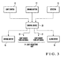
- a control device 20 is connected to a limit switch 12, the detector 13, a driving button 17, a driving motor 18, and an alarm device 19.
- the driving button 17 is a driving button for the printing press which is manipulated when starting cleaning of the impression cylinder 3.
- the driving motor 18 for driving printing press is driven to slowly rotate the impression cylinder 3.
- the alarm device 19 produces an alarm when paper dust or a liquid such as ink or varnish attaches to the light-projecting surface of the light-projecting unit 14 or the light-receiving surface of the light-receiving unit 15 and the detector 13 does not operate normally.
- the alarm device 19 produces an alarm when the light-projecting unit 14 does not sufficiently project the light 16 and the light-receiving unit 15 cannot obtain a predetermined output value, or when the light-receiving unit 15 does not accurately receive the light 16 from the light-projecting unit 14 and cannot obtain the predetermined output value.
- the control device 20 outputs a signal 21 for turning off the light-projecting unit 14 (light source) of the detector 13 when the limit switch 12 detects the closed state of the window 9a.
- the control device 20 also outputs a signal 22 for turning on the light-projecting unit 14 (light source) of the detector 13 when the closed state of the window 9a is not detected, i.e., when the window 9a is open. After that, when the detector 13 detects a rag or the like, the control device 20 controls to stop driving the driving motor 18.
- the step 10 is pivoted counterclockwise in Fig. 1 about the pivot shaft 11 as the pivotal center, and passes through the positions 10B and 10C to reach the position 10D to open the window 9a.
- the limit switch 12 is set in the non-detection state.
- the control device 20 turns off the light-projecting unit 14 (light source) of the detector 13 (step S1).
- a predetermined output from the light-receiving unit 15 is present (YES in step S2)
- the driving motor 18 is driven (step S3). This slowly rotates the impression cylinder 3.
- the control device 20 monitors the manipulation of the driving button 17 and the output from the light-receiving unit 15 (steps S4 and S5). When the driving button 17 is turned off (YES in step S4), the cleaning operation is ended.
- step S5 if the operator erroneously inserts the rag toward the opposing position A of the impression cylinder 3 and transfer cylinder 4 or drops it, the detector 13 having the detection optical path close to the opposing position A detects the rag (NO in step S5).
- the control device 20 thus stops driving of the driving motor 18 (step S6), and outputs an alarm indicating that the rag is detected (step S7).
- the detector 13 is arranged at the position spaced apart by the distance L2 from the position B where the rag or the like is caught between the impression cylinder 3 and transfer cylinder 4.
- the distance L2 is set equal to the length through which the impression cylinder 3, which has been rotating slowly, rotates until stopping at the position B by inertia since the detector 13 detects the rag or the like and sends the rotation stop signal.
- the impression cylinder 3 stops before the rag is transported to the opposing position A of the impression cylinder 3 and transfer cylinder 4.
- the rag will not damage or break the surfaces of the impression cylinder 3 and transfer cylinder 4. Since the non-contact detector 13 detects the rag, the detection optical path of the detector 13 can be set between the impression cylinder 3 and transfer cylinder 4 which transfer the sheet 5. This allows cleaning of the impression cylinder 3 during rotation, shortening the time required to clean the impression cylinder 3. Unlike in the conventional case, the detector 13 does not require a movable portion to detect the rag or the like. This can prevent erroneous detection caused by paper dust or a liquid such as ink or varnish.
- step S8 When the light-projecting unit 14 (light source) is turned on, if the predetermined output cannot be immediately obtained due to the soil of the light-projecting surface of the light-projecting unit 14 or the light-receiving surface of the light-receiving unit 15, as described above (NO in step S2), the alarm device 19 outputs an alarm indicating sensor abnormality (step S8). Since this embodiment can check the abnormality of the light-projecting unit 14 or light-receiving unit 15, erroneous detection caused by sensor abnormality can be prevented.
- the limit switch 12 only when the step 10 is at the position 10D, the limit switch 12 detects the step 10 and the window 9a is determined to be open. Alternatively, even when the step 10 is at the position 10B or 10C, the limit switch 12 may detect it and the window 9a may be determined to be open.
- the second embodiment of the present invention will be described with reference to Fig. 5.
- the second embodiment is different from the first embodiment in that, as shown in Fig. 5, a limit switch 23 which directly detects a step 10 that has moved to a position 10D is provided in addition to a limit switch 12.
- a controller turns on a light-projecting unit 14 (light source) of a detector 13.
- the third embodiment of the present invention will be described with reference to Fig. 6.
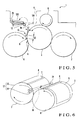
- the third embodiment is different from the first embodiment in that, as shown in Fig. 6, a pair of a light-projecting unit 14 and light-receiving unit 15 are arranged on one end side of each of an impression cylinder 3 and transfer cylinder 4, and a reflection plate 24 is provided on the other end side of each of the impression cylinder 3 and transfer cylinder 4. Also, in this arrangement, the reflection plate 24 reflects the light projected by the light-projecting unit 14, and the light-receiving unit 15 receives the reflected light.
- the light-projecting unit 14, light-receiving unit 15, and reflection plate 24 constitute a reflection type detector 13'.
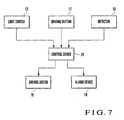
- the fourth embodiment of the present invention will be described with reference to Fig. 7.
- the fourth embodiment is different from the first embodiment in that, as shown in Fig. 7, a light-projecting unit 14 (light source) of a detector 13 is always ON regardless of the open/closed state of a step 10.
- a control device 25 controls to invalidate a detection output of the detector 13 when the step 10 is at a position indicated by 10A to keep a window 9a closed.
- the control device 25 also controls to validate the detection output of the detector 13 when the step 10 keeps the window 9a open.
- the control device 25 invalidates the detection output of the detector 13. Accordingly, even when the trailing edge of a sheet 5 which has been gripping-changed at a opposing position A of an impression cylinder 3 and transfer cylinder 4 flutters to block the portion between the light-projecting unit 14 and a light-receiving unit 15, the control device 25 determines that the detection operation of the detector 13 is invalid. Therefore, despite that the detector 13 has detected the sheet 5, a driving motor 18 does not stop driving, and ordinary printing operation continues.
- the control device 25 determines that the detection operation of the detector 13 is valid. This allows detection of the rag or the like entering the opposing position A of the impression cylinder 3 and transfer cylinder 4, and the same operation and effect as those of the first embodiment can be obtained.
- control device 20 or 25 disables the detector 13 itself or invalidates the detection output of the detector 13 when the closed state of the step 10 is detected. It suffices as far as the detector 13 is disabled to detect.
- the detection optical path of the detector 13 is set at a position close to the opposing position of the impression cylinder 3 and transfer cylinder 4.
- the detection optical path may be set at a position close to the opposing position of a transfer cylinder and transfer cylinder, a position close to the opposing position of an impression cylinder and delivery cylinder, a position close to the opposing position of a blanket cylinder and impression cylinder, or a position close to the opposing position of the blanket cylinder and a plate cylinder.
- the detection optical path may be arranged at a position close to the opposing position of a coater cylinder and impression cylinder in a coating apparatus, or a position close to the opposing position of an impression cylinder and impression cylinder in a perfector in which printing units are vertically arranged.
- the detection path can be set in the vicinity of a space between rotary bodies that transfer a sheet. This allows cleaning of the rotary bodies during rotation, shortening the time required to clean the rotary bodies.
- the detector need not be moved. Thus, no means for moving the detector is required, leading to a reduction in number of components and a simple structure.
- the detector does not require a movable portion to detect the rag or the like. This can prevent erroneous detection that occurs when paper dust or a liquid such as ink or varnish attaches to the movable portion.
Landscapes
- Engineering & Computer Science (AREA)
- General Engineering & Computer Science (AREA)
- Mechanical Engineering (AREA)
- Inking, Control Or Cleaning Of Printing Machines (AREA)
- Optical Transform (AREA)
- Centrifugal Separators (AREA)
Applications Claiming Priority (1)
| Application Number | Priority Date | Filing Date | Title |
|---|---|---|---|
| JP2006291245A JP2008105303A (ja) | 2006-10-26 | 2006-10-26 | 回転体の保護装置 |
Publications (2)
| Publication Number | Publication Date |
|---|---|
| EP1918098A2 true EP1918098A2 (de) | 2008-05-07 |
| EP1918098A3 EP1918098A3 (de) | 2008-05-21 |
Family
ID=38954609
Family Applications (1)
| Application Number | Title | Priority Date | Filing Date |
|---|---|---|---|
| EP07020052A Withdrawn EP1918098A3 (de) | 2006-10-26 | 2007-10-12 | Schutzvorrichtung für ein rotierendes Element |
Country Status (4)
| Country | Link |
|---|---|
| US (1) | US20080098914A1 (de) |
| EP (1) | EP1918098A3 (de) |
| JP (1) | JP2008105303A (de) |
| CN (1) | CN101168322B (de) |
Cited By (1)
| Publication number | Priority date | Publication date | Assignee | Title |
|---|---|---|---|---|
| EP2177359A4 (de) * | 2007-08-10 | 2011-04-06 | Komori Printing Mach | Flüssigtranskriptionsvorrichtung |
Families Citing this family (2)
| Publication number | Priority date | Publication date | Assignee | Title |
|---|---|---|---|---|
| JP5688246B2 (ja) * | 2010-08-05 | 2015-03-25 | スタンレー電気株式会社 | 透明体およびその製造方法 |
| CN108903769B (zh) * | 2018-03-31 | 2023-11-21 | 天佑电器(苏州)有限公司 | 箱式组合工具、背带卡扣组件及背带的装配方法 |
Citations (1)
| Publication number | Priority date | Publication date | Assignee | Title |
|---|---|---|---|---|
| JP2001171087A (ja) | 1999-12-17 | 2001-06-26 | Komori Corp | 回転体の保護装置 |
Family Cites Families (12)
| Publication number | Priority date | Publication date | Assignee | Title |
|---|---|---|---|---|
| US3805061A (en) * | 1973-04-23 | 1974-04-16 | Tyco Laboratories Inc | Object detecting apparatus |
| US3912924A (en) * | 1973-11-07 | 1975-10-14 | Link Electric & Safety Control | Machine safety control |
| DE2430536C2 (de) * | 1974-06-26 | 1981-03-19 | M.A.N.- Roland Druckmaschinen AG, 6050 Offenbach | Einrichtung zur Sicherung von Schutzgittern bzw. Schutzabdeckungen an Druckmaschinen |
| DD134933A1 (de) * | 1978-03-16 | 1979-04-04 | Hans Johne | Schutzvorrichtung,insbesondere an druckmaschinen |
| DD212024A1 (de) * | 1982-12-14 | 1984-08-01 | Winfried Buesse | Einrichtung zur kontrolle der bogenuebergabe in rotationsdruckmaschinen |
| DE3441963C2 (de) * | 1984-11-16 | 1987-01-22 | M.A.N.- Roland Druckmaschinen AG, 6050 Offenbach | Sicherheitseinrichtung an Bogenrotationsdruckmaschinen |
| US5243183A (en) * | 1992-09-15 | 1993-09-07 | Triad Controls, Inc. | Obstruction position detecting system with comparison and memory means |
| US5844487A (en) * | 1997-08-20 | 1998-12-01 | Britt; Paul E. | Alert alarm responsive to an unaccompanied child |
| DE19940534B4 (de) * | 1998-10-14 | 2009-09-03 | Heidelberger Druckmaschinen Ag | Druckmaschine mit einer Fingerschutzeinrichtung |
| ATE260768T1 (de) * | 2000-05-16 | 2004-03-15 | Komori Printing Mach | Sicherheitseinrichtung für eine rollenrotationsmaschine |
| DE102004002660B4 (de) * | 2003-01-31 | 2013-06-13 | Heidelberger Druckmaschinen Ag | Verfahren zum Betreiben einer Bogendruckmaschine und Bogendruckmaschine zur Durchführung dieses Verfahrens |
| DE102004055229A1 (de) * | 2004-11-17 | 2006-05-18 | Heidelberger Druckmaschinen Ag | Zustandsabhängige Absicherung von Maschinen |
-
2006
- 2006-10-26 JP JP2006291245A patent/JP2008105303A/ja active Pending
-
2007
- 2007-10-12 EP EP07020052A patent/EP1918098A3/de not_active Withdrawn
- 2007-10-17 US US11/975,238 patent/US20080098914A1/en not_active Abandoned
- 2007-10-23 CN CN200710180291.7A patent/CN101168322B/zh not_active Expired - Fee Related
Patent Citations (1)
| Publication number | Priority date | Publication date | Assignee | Title |
|---|---|---|---|---|
| JP2001171087A (ja) | 1999-12-17 | 2001-06-26 | Komori Corp | 回転体の保護装置 |
Cited By (2)
| Publication number | Priority date | Publication date | Assignee | Title |
|---|---|---|---|---|
| EP2177359A4 (de) * | 2007-08-10 | 2011-04-06 | Komori Printing Mach | Flüssigtranskriptionsvorrichtung |
| US8166878B2 (en) | 2007-08-10 | 2012-05-01 | Komori Corporation | Liquid transfer apparatus |
Also Published As
| Publication number | Publication date |
|---|---|
| JP2008105303A (ja) | 2008-05-08 |
| CN101168322A (zh) | 2008-04-30 |
| CN101168322B (zh) | 2010-11-24 |
| EP1918098A3 (de) | 2008-05-21 |
| US20080098914A1 (en) | 2008-05-01 |
Similar Documents
| Publication | Publication Date | Title |
|---|---|---|
| WO2007097308A1 (ja) | 印刷機および印刷機の排紙装置 | |
| JPH0623971A (ja) | 枚葉紙長さを測定するための装置 | |
| US20080098914A1 (en) | Rotary body protecting apparatus | |
| JP2001146347A (ja) | 被印刷体処理機械における帯状材の巻き取り方法、巻き取り装置、および被印刷体処理機械 | |
| JP4243056B2 (ja) | 運動方向反転の際に枚葉紙状の材料の位置を適合させるための装置 | |
| US5944431A (en) | Sheet sensor device with light curtain | |
| JP4160647B2 (ja) | 枚葉紙センサ装置 | |
| US5024155A (en) | Finger protecting element for cylinder nip | |
| US9446582B2 (en) | Perfector | |
| EP3208095A1 (de) | Digitaldrucker | |
| JP2642560B2 (ja) | 枚葉紙輪転印刷機の横方向案内および引き過ぎ監視装置 | |
| JP6840047B2 (ja) | 印刷機を制御して印刷機の搬送装置を停止させる方法 | |
| JPH0311272B2 (de) | ||
| JP2000117948A (ja) | 指保護装置を備えた印刷機および印刷機を運転する方法 | |
| US20090295057A1 (en) | Sheet monitor for folding machine | |
| JP4280323B2 (ja) | 枚葉紙をインキ汚れなく送る方法および装置 | |
| US7506585B2 (en) | Method of operating a press | |
| JP2666146B2 (ja) | 枚葉印刷機の紙送り異常検出装置 | |
| JP3994318B2 (ja) | 枚葉紙を処理するための方法及び装置 | |
| JPH0399853A (ja) | 印刷用紙の紙押え方法及びその装置 | |
| JP3061941B2 (ja) | 孔版印刷装置 | |
| JP4554952B2 (ja) | 枚葉紙印刷機を運転する方法、およびこの方法を実施する枚葉紙印刷機 | |
| JPH02233434A (ja) | 給紙装置の用紙検出機構 | |
| US7637209B2 (en) | Method of changing the mounting condition of a printing master on a printing master cylinder | |
| JP3652483B2 (ja) | 原稿自動搬送装置 |
Legal Events
| Date | Code | Title | Description |
|---|---|---|---|
| PUAI | Public reference made under article 153(3) epc to a published international application that has entered the european phase |
Free format text: ORIGINAL CODE: 0009012 |
|
| PUAL | Search report despatched |
Free format text: ORIGINAL CODE: 0009013 |
|
| AK | Designated contracting states |
Kind code of ref document: A2 Designated state(s): AT BE BG CH CY CZ DE DK EE ES FI FR GB GR HU IE IS IT LI LT LU LV MC MT NL PL PT RO SE SI SK TR |
|
| AX | Request for extension of the european patent |
Extension state: AL BA HR MK RS |
|
| AK | Designated contracting states |
Kind code of ref document: A3 Designated state(s): AT BE BG CH CY CZ DE DK EE ES FI FR GB GR HU IE IS IT LI LT LU LV MC MT NL PL PT RO SE SI SK TR |
|
| AX | Request for extension of the european patent |
Extension state: AL BA HR MK RS |
|
| 17P | Request for examination filed |
Effective date: 20081112 |
|
| AKX | Designation fees paid |
Designated state(s): AT BE BG CH CY CZ DE DK EE ES FI FR GB GR HU IE IS IT LI LT LU LV MC MT NL PL PT RO SE SI SK TR |
|
| 17Q | First examination report despatched |
Effective date: 20090115 |
|
| GRAP | Despatch of communication of intention to grant a patent |
Free format text: ORIGINAL CODE: EPIDOSNIGR1 |
|
| INTG | Intention to grant announced |
Effective date: 20130506 |
|
| STAA | Information on the status of an ep patent application or granted ep patent |
Free format text: STATUS: THE APPLICATION IS DEEMED TO BE WITHDRAWN |
|
| 18D | Application deemed to be withdrawn |
Effective date: 20130503 |