EP1918158A2 - Dispositif de fixation de charge pour véhicules dotés d'une plateforme de charge - Google Patents
Dispositif de fixation de charge pour véhicules dotés d'une plateforme de charge Download PDFInfo
- Publication number
- EP1918158A2 EP1918158A2 EP07017577A EP07017577A EP1918158A2 EP 1918158 A2 EP1918158 A2 EP 1918158A2 EP 07017577 A EP07017577 A EP 07017577A EP 07017577 A EP07017577 A EP 07017577A EP 1918158 A2 EP1918158 A2 EP 1918158A2
- Authority
- EP
- European Patent Office
- Prior art keywords
- separating element
- rails
- elements
- loading zone
- adjusting
- Prior art date
- Legal status (The legal status is an assumption and is not a legal conclusion. Google has not performed a legal analysis and makes no representation as to the accuracy of the status listed.)
- Withdrawn
Links
- 230000007246 mechanism Effects 0.000 claims description 7
- 230000008901 benefit Effects 0.000 description 4
- 238000003780 insertion Methods 0.000 description 4
- 230000037431 insertion Effects 0.000 description 4
- 238000005192 partition Methods 0.000 description 4
- 230000006378 damage Effects 0.000 description 3
- 239000000463 material Substances 0.000 description 3
- 239000000758 substrate Substances 0.000 description 3
- 230000006978 adaptation Effects 0.000 description 2
- 230000000694 effects Effects 0.000 description 2
- 238000000034 method Methods 0.000 description 2
- 238000000926 separation method Methods 0.000 description 2
- 208000027418 Wounds and injury Diseases 0.000 description 1
- 238000010276 construction Methods 0.000 description 1
- 230000008878 coupling Effects 0.000 description 1
- 238000010168 coupling process Methods 0.000 description 1
- 238000005859 coupling reaction Methods 0.000 description 1
- 230000001419 dependent effect Effects 0.000 description 1
- 230000006866 deterioration Effects 0.000 description 1
- 230000002349 favourable effect Effects 0.000 description 1
- 208000014674 injury Diseases 0.000 description 1
- 238000004519 manufacturing process Methods 0.000 description 1
- 230000002265 prevention Effects 0.000 description 1
- 239000000725 suspension Substances 0.000 description 1
Images




Classifications
-
- B—PERFORMING OPERATIONS; TRANSPORTING
- B60—VEHICLES IN GENERAL
- B60P—VEHICLES ADAPTED FOR LOAD TRANSPORTATION OR TO TRANSPORT, TO CARRY, OR TO COMPRISE SPECIAL LOADS OR OBJECTS
- B60P7/00—Securing or covering of load on vehicles
- B60P7/06—Securing of load
- B60P7/135—Securing or supporting by load bracing means
- B60P7/14—Securing or supporting by load bracing means the load bracing means comprising a movable bulkhead
Definitions
- the invention relates to a device for securing cargo for according to the preamble of claim 1.
- Load securing for transport vehicles is an essential part of accident prevention measures or measures to reduce the consequences of accidents.
- the general cargo In the PkW area, but especially in the field of commercial freight transport bulk cargo is transported, the general cargo is typically stored on a bed of the transport vehicle and there remains largely unsecured.
- abrupt changes in speed of the transport vehicle such as heavy braking or heavy steering movements, it often happens that the cargo slips on the bed and leads to a hazard to the vehicle and driver. This has already caused many very serious accidents with high financial losses and personal injury.
- Lashing straps that need as flexible elements Although attachment points on the structure of the truck, but are easier to handle by the flexibility of the belt.
- the belt is fixed with one or more straps on the back, with the lashing straps is clamped between body-side suspension points.
- the disadvantage of this is the heavy wear of the straps by the tensioning process, which leads quickly to a destruction of the straps or to a deterioration of their safety and again to insufficient load security despite the use of such lashing straps.
- Object of the present invention is therefore to propose a device for securing cargo for transport vehicles, which is easy to use and thus easy to secure goods to be transported.
- the invention relates to a device for securing cargo for vehicles with a loading area, comprising a separating element between a occupied during the transport of objects area and a transport of objects unoccupied area of a loading zone of the vehicle.
- a generic device is further developed in that the at least one separating element has a plate-shaped basic shape and adjustable on a arranged in the loading zone rail system, the loading zone such that arranged in the loading zone between the walls of the loading zone and the separating element or between adjacent Dividing elements are held held against slipping safe.
- the areal separation with the aid of the plate-shaped separating elements can be easily adapted to the respective size of the goods to be secured by the adjustment in the rail system and separates the goods separated in each case against slippage due to the plate-shaped design of the separating elements substantially completely.
- the load securing can be done easily especially in small loaders and coaches, but also in trucks or other vehicles as well as ships, aircraft or the like. And thus significantly increase the acceptance for carrying out such load securing measures.
- the separating element consists of several plate-like individual elements which are slidably or foldably fixed to each other and with which the size of the separating element the dimensions of the loading zone and the objects to be transported are customizable.
- the separating element By dividing the separating element into a plurality of plate-like individual elements, it can be ensured that, depending on the size of the material to be protected, a more or less large area of the space can be divided off.
- the effective surface of the separating element can be adjusted accordingly and to be protected good separated more or less area of the other goods in the loading zone.
- a plurality of separating elements are arranged one behind the other in the region of the loading zone in the adjustment direction of the rails.
- the loading zone can be subdivided into a plurality of partitioned regions, which are arranged one behind the other in the loading direction and after loading of the first material a first separating element is introduced into the loading zone, after which another material can be loaded and separated by another separating element Adjustment of the rails in turn can be separated from a third or further areas.
- the rails are arranged for adjusting the separating element on the upper and lower walls of the vehicle in the region of the loading zone.
- the roof area over a loading zone is usually reinforced so that it can be attached to the rails for adjusting the separation element and strong enough.
- the separating element between the underlying, located in the support of the loading zone rails and the roof-mounted rails can be fixed and thus formed a total of very stiff or arranged.
- the rails for adjusting the separating element are arranged on the lateral walls of the vehicle in the region of the loading zone. This is especially useful if, for example, in the case of lorries, the roof area above the loading zone is not constructed so constructively that the loads occurring during braking or the like can be transmitted, as is the case, for example, in flexible superstructures of lorries. Then the rails can be arranged in the usually stiffer lateral area of the vehicle and the separating element hangs between the laterally arranged rails in the loading zone of the vehicle this is also the case with other vehicles such as passenger cars or small load transporters, if this should bring corresponding advantages in terms of loading or the like.
- a first structural embodiment provides that the rails for adjusting the separating element has a pair of mutually parallel, mutually spaced individual rails. Such arranged parallel to each other and spaced individual rails offer the opportunity to initiate the securing forces exerted on the separating element holding forces at spaced points on the rails in the vehicle and thus not only forces, but also load moments can safely catch.
- the distance between the rails from each other ensures that the resulting forces, for example, during braking or the like, not only selectively introduced into the vehicle body, but are transmitted simultaneously to the body at several points.
- the rails are recessed flush for adjusting the separating element in the ground or the walls of the vehicle.
- the rails are not in such a flush design, especially in the region of the support surface of the loading zone on the support surface of the loading zone and therefore can not interfere with the loading of the loading zone.
- the rails which are flush-mounted in the walls of the vehicle, as a result, a snagging of goods can not be done on these rails.
- the rails for adjusting the separating element substantially have a C-shaped, open to the loading zone cross-section and, for example, have projections or undercuts, where adapter elements of the separating element can be fixed.
- Such rails are easy to manufacture and provide for part of the partition elements arranged adapter elements on the one hand a good attack surface, on the other hand, for example, by a narrow opening of the rails to the loading zone out to ensure that no objects can fall into the rails and interfere with the onset of the separating elements.
- the rails extend for the adjustment of the separating element substantially over the entire length of the loading zone. This allows Goods of very different dimensions at almost any point of the charging zone of the vehicle are securely fixed, so that for example in the rear of a vehicle even the last room can be exploited without having to forego the benefits of securing cargo through the separating elements.
- a particular advantage with regard to the security of the load securing by the separating element according to the invention is when the separating element is mounted in the intended use state on both sides in the rails for adjusting the separating element. Due to the two-sided storage of the separating element as well as the design of the separating element as a substantially plate-shaped component can be achieved over the entire surface of the separating element a very stable load securing, so that goods of different vertical dimensions can be safely determined by the introduction of a separating element. As a result, tilting loads, which can be caused for example by towering goods in the loading zone, can be intercepted by the separating element and safely introduced into the vehicle body.
- the separating element is mounted and adjustable in the rails for adjusting the separating element such that the separating element can be moved parallel to the rails within the loading zone.
- usually rectangular goods whose outer dimensions extend approximately parallel or perpendicular to the arrangement of the rails are fixed in a particularly simple manner by the separating elements, as the separating elements simply pushed parallel to the rails in the loading zone to or from the rear can be.
- the separating element is mounted and adjustable in such a way in the rails for adjusting the separating element, that the separating element can also be arranged obliquely within the loading zone. In this way it can be achieved that irregularly shaped goods or eg round tons or the like, which must be set in the loading zone, also pressed by an inclined position of the separating element, for example against an adjacent partition member or the walls of the loading zone and thus fixed.
- the separating element is held in such a way in the rails for adjusting the separating element, that the separating element can be fixed in its respective intended position.
- the operation of the separating element can be very simplified and nevertheless a fine adjustment of the position of the separating element can be achieved relative to the goods to be secured , This increases the acceptance of the transport personnel, as a result of the loading and the load securing are not significantly extended against unsecured loading of goods.
- a separating element can be brought into a position such as a loading ramp, with the loading of objects in the loading zone is simplified.
- a separating element can be spent, for example, during loading of the loading zone in this position and then serve as a loading dock for introducing the goods to be transported, what else a special loading ramp would have to be carried and therefore, especially in the field of small load transporters this does not normally take place.
- the separating element has a number of beam elements, preferably two beam elements, on which plate-shaped individual elements are arranged.
- Such a design of individual beam elements arranged thereon with plate-shaped individual elements has the advantage that the separating elements on the one hand stiff on the one hand, on the other hand, but relatively lightweight can be performed without the quality and safety of load securing would suffer.
- the beam elements in this case have the main task of transferring the loads from the separating element to the rails and thus to the vehicle body, whereas the separating plates have to produce the substantially flat cover between the individual sections of the loading zone.
- the plate-shaped individual elements can be made much lighter weight, as if the separator plates would have to take over the load transfer to the rails.
- care can be taken in a further embodiment; that the beam elements have adapter elements at both ends, on which the beam elements are held and adjustable in the rails for adjusting the separating element.
- Such adapter elements can be fixed to the rails, for example via clamps, screw connections or the like, so that any intermediate positions for the adjustment of the beam elements and thus of the separating elements relative to the goods to be secured are adjustable.
- the separating element with the adapter elements can be detached from the rails for adjusting the separating element on one side, so that the separating element can be folded around the adapter elements remaining in the other rails.
- Such a foldable design of the separating elements can be used to fold the separating elements in the unused state to the sides or the ceiling of the loading zone and fix it there, so that the separating elements in the unused state require little space and do not disturb the charging itself. It is conceivable that the separating element can be folded upwards, to the side or downwards, depending on which adapter element or which adapter elements are released and on which side or in which direction the separating element is to be folded.
- the separating element with the adapter elements of the rails for adjusting the separating element is detachable, so that the separating element from the loading zone is completely removable. As a result, the separating element can be removed altogether from the loading zone of the vehicle, if it is not required by the corresponding loading conditions.
- a simple way of coupling the separating element to the rails can be achieved in that the adapter elements have sliders which are displaceable within the rails for adjusting the separating element.
- Such sliders can be determined, for example, by clamping on the rails in the region of undercuts or other form elements, when the separating element is fixed and thereby effect a secure fixing of the separating element to the rails.
- This can be achieved for example by the fact that the sliders and the bar element side arranged parts of the adapter element are releasably connected to each other. The sliders remain within the rails and can be used again accordingly for the next setting of the separating elements.
- the separating element with the adapter elements on the upper rails for adjusting the separating element in the cargo area hanging be movable, which in particular the operation of the separating element is greatly simplified because the separating element quasi weight relieved displaced within the cargo area and at the most favorable Space for load securing can be redefined again.
- the adapter elements have head pieces which can be inserted into the rails for adjusting the separating element and locked to the rails.
- the connection parts of the adapter elements are arranged on the adapter elements themselves and remain thereon, so that the adapter elements can be inserted into the rails with these connection elements and fixed in a bayonet-like manner, for example by turning.
- the head pieces are formed in cross-section suitable for counter-shaped depressions in the rails and move when locking transversely to the longitudinal extension of the rails in the wells and can be locked in this position.
- the cross-section of the head pieces secures the head pieces secured against rotation in the recesses, a simple and secure fixing of the separating element to the rail can be achieved thereby.
- rod-like locking mechanisms are arranged on the beam elements with which the head pieces on the rails for adjusting the separating element in the longitudinal direction of the beam elements are adjustable and lockable.
- the rod-like locking mechanisms transmit the locking movement of the head pieces along the beam elements of a handle conveniently, for example, centrally arranged handle to the two end of the beam element, so that the operator of the separating element a comfortable handling of the separating element is made possible.
- Such locking mechanisms can be about Rod bars or the like. Have, as they are known for example from the field of window fittings and in which a relatively low weight with high strength of the locking mechanisms is associated.
- rod-like locking mechanisms press or push together the headpieces arranged at the top and bottom of the beam elements in opposite directions when the beam elements are locked or unlocked.
- the locking and unlocking can be effected at both ends of the beam element simultaneously and with a single operation.
- the plate elements are mounted slidably on the beam elements, that when tilting the plate elements relative to the walls of the loading zone an adjustment of the distance of the beam elements can be made relative to the separating elements ,
- the spacing between the beam members changes and becomes greater than when the beam members are disposed perpendicularly relative to the rails, such that the beam members must be displaceable by a corresponding balancing movement relative to the separator members to continue to be seated in the rails of the loading zone to be able to guarantee.
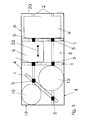
- FIGS. 1 to 5 show a first embodiment of the device according to the invention, in which a vehicle, indicated only schematically, is provided with a boundary 6 of the loading zone 3 with partition elements 1 designed according to the invention.
- the boundary 6 of the loading zone 3 for example, the load compartment of a van or the like, are transported with the goods in the form of objects 9, 10. It may of course also be any other type of vehicle such as cars, trucks or even ships or aircraft having a corresponding cargo space.
- the loading zone 3 is in this case by a bottom, two side walls 4, a front wall 19, for example, in the direction of a driver's cab, not shown, and a rear wall 20, which may be designed in the form of a loading opening at the same time.
- the dividing elements 1 are essentially plate-shaped components, in the middle region of which two bar elements 5 are clamped and held between upper and lower rails 2.
- the rails 2 are, for example, flush with the loading area and in the roof space of the boundary 6 of the loading zone 3 and provide a holding possibility for arranged on the beam elements 5, not shown adapter elements. These adapter elements thus anchor themselves in the rails 2 and clamp the beam elements 5 between the rails 2 arranged on the upper side and on the underside.
- Individual elements arranged in the form of a middle part 21, side parts 15 and a head part 18 can be arranged relative to the beam elements 5 on the beam elements 5 8 and thus offer an adaptation possibility of the size of the separating element 1 relative to the objects 9, 10 to be secured respectively, or the dimensions of the boundary 6 of the loading zone 3.
- FIG. 1 it is shown that two individual separating elements 1 are arranged in the loading zone 3 in the adjustment direction 22 of the rails 2 in a row and are substantially perpendicular to the adjustment direction 22 within the loading zone 3.
- the dividing elements 1 are arranged as shown in Figure 3 within the loading zone 3, that the objects 9, 10 can be supported respectively on the separating elements 1 and the walls 4, 19, 20 and therefore a possibility of movement of the objects 9, 10th essentially no longer exists.
- the separating element 1 can also be arranged obliquely within the loading zone 3 in order to effect a secure clamping of the round object 10, for example in a corner of the boundary 6 of the loading zone 3 or between adjacent separating elements 1, without the round object 10 can slip laterally.
- the fixing of the separating elements 1 oriented perpendicular to the adjustment direction 22 is sufficient.
- separating elements 1 in the rails 2 serve not shown adapter elements with which the dividing elements 1 can be fixed to the respective end of beam elements 5 in the rails 2, for example, non-positively or positively.
- a variety of technical solutions is conceivable, for example, in a C-shaped rail 2 a corresponding clamping body may be used, in which by means of a thread, a clamping element is screwed and thus fixes the clamping body to the rail 2.
- the separating elements 1 can also be detached from the rails 2 on one side and then folded away, for example, upwards, and thus the loading zone 3 can be held releasably.
- hinges or the like are provided on the adapter elements with which the separating element 1 remaining over the adapter elements in a pair of rails 2 is suspended, for example, and by loading and securing the separating element 1 completely releases the loading zone 3 for loading.
- FIG. 5 shows an application of a shaped separating element 1 according to the invention in such a way that the separating element 1 can be used in the form of a loading ramp in the region of the rear loading opening 20.
- An example as Vans trained vehicle with the device according to the invention is usually designed so that the bottom of the loading zone 3 is arranged by the wheels 12 at a corresponding distance from a substrate 11 and arranged on the cargo area objects 9, 10 therefore overcome this height difference during unloading and loading have to.
- a separating element 1 designed according to the invention can be arranged in the rails 2 in the region of the loading opening 20 such that it connects the rear area of the loading zone 3 and the substrate 1 in the form of a loading ramp.
- the separating element 1 only the adapter elements of the separating element 1 are left unilaterally in the lower rails 2 and the separating element 1 folded outwards out of the vehicle and parked with its other end on the substrate 11.
- the loading and unloading of vehicles that do not have a standard loading dock or lifting platform can be significantly simplified.
- the separating element 1 can be reclined normally and used to secure the invited objects 9, 10.
- FIG. 6 and 7 another embodiment of the device according to the invention is shown, in which the rails 2 are not arranged in the bottom area and in the ceiling region of the boundary 6 of the loading zone 3, but in the side walls 4.
- Such an arrangement of the rails 2, the otherwise substantially equivalent to the previously described arrangement of the rails 2 in the floor area and in the roof area of the vehicle makes, under certain circumstances, depending on the space within the loading zone 3 of the vehicle sense.
- the separating element 1 can be correspondingly folded away from the loading zone 3 against the side wall 4.
- FIG. 8 shows the possibilities of how the separating element 1 can be made adjustable from a beam element 5 and individual elements in the form of side parts 15, a head part 18 and a middle part 21.
- the beam elements 5 take in this case mainly the loads, for example, due to braking, which can exert the objects 9, 10 on the separating elements 1-
- To adapt the separating element 1 to the dimensions of the articles 9, 10 and the dimensions of the boundary 6 of the loading zone 3 can two side parts 15 issued by a lateral raising movement 13 or by a lateral insertion movement 14 are retracted again. It is also possible to extend the separating element 1 by a vertical insertion movement 17 upwards or down again.
- the partition element 1 can be made substantially lighter overall, as could be the case with a one-piece design.
- a beam element 5 is shown, in which the rails 2 shown on the upper side and underside can be fixed in the rails by means of slides 25, 27.
- a rod drive from the rods 24 for the slide 25, 27 is provided inside the approximately formed from a profile bar element, which ensures by means of a lever 23 that the slide 25, 27 when locking in the longitudinal direction of the beam element 5 outwardly extended and
- the slides 25, 27 in this case engage in the correspondingly shaped recesses of the rails 2 and prevent longitudinal movement of the beam element 5 and thus of the separating element 1.
- the beam element 5 Transversely to the longitudinal direction of the rails 2, the beam element 5 by T-piece shaped elements secured, which are formed according to the example in cross section also T-piece shaped rails 2 and slidably received in the rails.
- FIG. 13 shows a lower end region of the beam element 5 according to FIG. 9 with a guide element 30 arranged thereon, the guide element 30 serving to guide the beam element 5 in the rail 2.
- the guide element 30 serving to guide the beam element 5 in the rail 2.
- the guide element 30 may be formed, for example, as shown in the figure 13 as a separate, angular-like part, one leg of which is fixed to the beam element 5 and the other leg protrudes into the rail 2 into it. But it is also conceivable that the guide member 30 is integrally formed from the beam member 5 or from the slide 23, 25.
Landscapes
- Engineering & Computer Science (AREA)
- Transportation (AREA)
- Mechanical Engineering (AREA)
- Fittings On The Vehicle Exterior For Carrying Loads, And Devices For Holding Or Mounting Articles (AREA)
- Loading Or Unloading Of Vehicles (AREA)
Applications Claiming Priority (1)
| Application Number | Priority Date | Filing Date | Title |
|---|---|---|---|
| DE200610051248 DE102006051248A1 (de) | 2006-10-26 | 2006-10-26 | Einrichtung zur Ladungssicherung für Fahrzeuge mit einer Ladefläche |
Publications (2)
| Publication Number | Publication Date |
|---|---|
| EP1918158A2 true EP1918158A2 (fr) | 2008-05-07 |
| EP1918158A3 EP1918158A3 (fr) | 2009-09-23 |
Family
ID=38989885
Family Applications (1)
| Application Number | Title | Priority Date | Filing Date |
|---|---|---|---|
| EP07017577A Withdrawn EP1918158A3 (fr) | 2006-10-26 | 2007-09-07 | Dispositif de fixation de charge pour véhicules dotés d'une plateforme de charge |
Country Status (2)
| Country | Link |
|---|---|
| EP (1) | EP1918158A3 (fr) |
| DE (1) | DE102006051248A1 (fr) |
Cited By (1)
| Publication number | Priority date | Publication date | Assignee | Title |
|---|---|---|---|---|
| CN113734038A (zh) * | 2021-09-29 | 2021-12-03 | 眉山中车物流装备有限公司 | 一种侧帘半挂车格挡及捆绑装置结构 |
Families Citing this family (4)
| Publication number | Priority date | Publication date | Assignee | Title |
|---|---|---|---|---|
| DE102008039648A1 (de) | 2008-08-19 | 2010-03-04 | Seebauer, Kurt | Elemente für eine Einrichtung zur Ladungssicherung für Fahrzeuge mit einer Ladefläche |
| DE102011100465A1 (de) * | 2011-05-02 | 2012-11-08 | Thomas Ortlieb | Modular aufbaubares Ladungssicherungssystem mit schnellspannenden Befestigungsmitteln |
| WO2022236059A1 (fr) | 2021-05-07 | 2022-11-10 | Redkik Oy | Évaluation de probabilité de risque pour des opérations d'expédition de marchandises, et procédés pour son utilisation |
| CN115071547B (zh) * | 2022-08-10 | 2023-10-24 | 蒙城财富汽车有限公司 | 一种半挂车钢材运输用固定结构及其使用方法 |
Citations (4)
| Publication number | Priority date | Publication date | Assignee | Title |
|---|---|---|---|---|
| US5386674A (en) | 1992-09-17 | 1995-02-07 | Joseph T. Ryerson & Son, Inc. | Two piece bulkhead door for rail cars and the like |
| DE202005005929U1 (de) | 2005-04-12 | 2005-07-07 | Allsafe Jungfalk Gmbh & Co. Kg | Schottwand zum Einsetzen in den Innenraum eines Fahrzeuges |
| US20050152761A1 (en) | 2003-11-03 | 2005-07-14 | Silamianos Bill M. | Divider apparatus and method for use with a bed of a motor vehicle |
| US20050207860A1 (en) | 2000-07-20 | 2005-09-22 | Fg Products, Inc., A Wisconsin Corporation | Bulkhead lift apparatus |
Family Cites Families (4)
| Publication number | Priority date | Publication date | Assignee | Title |
|---|---|---|---|---|
| US4082044A (en) * | 1975-09-29 | 1978-04-04 | The Coca-Cola Company | Adjustable fluid dunnage system |
| CA1239052A (fr) * | 1986-06-23 | 1988-07-12 | Joseph W. Cox | Dispositif et accessoires d'arrimage reglables pour emploi sur vehicule transporteur |
| US5961171A (en) * | 1996-08-02 | 1999-10-05 | Iijima; Shunichi | Partition device in vehicular trunk |
| DE10134887B4 (de) * | 2001-07-18 | 2006-01-19 | Daimlerchrysler Ag | Befestigungsvorrichtung zum Haltern und/oder Sichern von Gegenständen in einem Fahrzeugladeraum |
-
2006
- 2006-10-26 DE DE200610051248 patent/DE102006051248A1/de not_active Withdrawn
-
2007
- 2007-09-07 EP EP07017577A patent/EP1918158A3/fr not_active Withdrawn
Patent Citations (4)
| Publication number | Priority date | Publication date | Assignee | Title |
|---|---|---|---|---|
| US5386674A (en) | 1992-09-17 | 1995-02-07 | Joseph T. Ryerson & Son, Inc. | Two piece bulkhead door for rail cars and the like |
| US20050207860A1 (en) | 2000-07-20 | 2005-09-22 | Fg Products, Inc., A Wisconsin Corporation | Bulkhead lift apparatus |
| US20050152761A1 (en) | 2003-11-03 | 2005-07-14 | Silamianos Bill M. | Divider apparatus and method for use with a bed of a motor vehicle |
| DE202005005929U1 (de) | 2005-04-12 | 2005-07-07 | Allsafe Jungfalk Gmbh & Co. Kg | Schottwand zum Einsetzen in den Innenraum eines Fahrzeuges |
Cited By (1)
| Publication number | Priority date | Publication date | Assignee | Title |
|---|---|---|---|---|
| CN113734038A (zh) * | 2021-09-29 | 2021-12-03 | 眉山中车物流装备有限公司 | 一种侧帘半挂车格挡及捆绑装置结构 |
Also Published As
| Publication number | Publication date |
|---|---|
| EP1918158A3 (fr) | 2009-09-23 |
| DE102006051248A1 (de) | 2008-04-30 |
Similar Documents
| Publication | Publication Date | Title |
|---|---|---|
| EP2185382B1 (fr) | Dispositif de fixation d'un conteneur sur la plate-forme d'un vehicule de transport | |
| DE3438079A1 (de) | Hubvorrichtung fuer den kofferraum eines fahrzeuges zum entnehmen und einbringen unhandlicher gegenstaende | |
| DE102020118478B4 (de) | Frachtbrücke für Verkehrsflugzeug und Verkehrsflugzeug | |
| EP2100801B1 (fr) | Dispositif de sécurisation du chargement d'un véhicule utilitaire, procédé de sécurisation du chargement et véhicule utilitaire doté d'un tel dispositif | |
| DE202008016326U1 (de) | Vorrichtung zur Sicherung von Ladung | |
| DE202015106050U1 (de) | Entfernbare Rahmensysteme für den Fahrzeugtransport | |
| DE2923428A1 (de) | Transportabler container fuer den transport von personenkraftwagen | |
| EP0737601B1 (fr) | Dispositif pour éviter le glissement des objets transportés sur des plate-formes de charge de véhicules | |
| DE102018122634B4 (de) | Ladungs-Sicherungs-System sowie Fahrzeug umfassend ein solches System und ein Verfahren zur Ladungs-Sicherung | |
| DE102004011003B4 (de) | Sperrsystem zur Ladungssicherung | |
| EP3699057A1 (fr) | Dispositif porteur élevable | |
| DE2423322B2 (de) | Eisenbahngueterwagen fuer den transport von fahrzeugen, wohnwagen und booten | |
| EP2368759B1 (fr) | Procédé de sécurisation d'un objet de chargement et système de sécurisation de chargement | |
| DE69715832T2 (de) | Kippbare Rampe für die Ladefläche eines Kraftfahrzeugs | |
| DE102006051248A1 (de) | Einrichtung zur Ladungssicherung für Fahrzeuge mit einer Ladefläche | |
| DE102022127514B4 (de) | Kraftfahrzeug mit einer Auszugsvorrichtung für eine Transporteinrichtung und Verfahren zum Betreiben eines Kraftfahrzeugs | |
| DE2802267A1 (de) | Lastzug zum transport von fahrzeugen, insbesondere von mittleren und schweren industriefahrzeugen | |
| DE10260524A1 (de) | Höhenverstellbarer Laderaumboden | |
| DE102020112000B4 (de) | Multifunktionaler Anhänger | |
| DE29606845U1 (de) | Hilfsrahmen für einen Lastkraftwagen für den Transport von Wechselbehältern | |
| DE102023201558A1 (de) | Kraftfahrzeug | |
| EP1043188A2 (fr) | Installation pour un espace de chargement de véhicules ou conteneurs de transport | |
| EP4484216B1 (fr) | Remorque pour le transport de conteneurs | |
| DE102012108527B4 (de) | Lastfahrzeug mit einem Schutzrahmen | |
| DE9316693U1 (de) | Wechselpritsche |
Legal Events
| Date | Code | Title | Description |
|---|---|---|---|
| PUAI | Public reference made under article 153(3) epc to a published international application that has entered the european phase |
Free format text: ORIGINAL CODE: 0009012 |
|
| AK | Designated contracting states |
Kind code of ref document: A2 Designated state(s): AT BE BG CH CY CZ DE DK EE ES FI FR GB GR HU IE IS IT LI LT LU LV MC MT NL PL PT RO SE SI SK TR |
|
| AX | Request for extension of the european patent |
Extension state: AL BA HR MK RS |
|
| PUAL | Search report despatched |
Free format text: ORIGINAL CODE: 0009013 |
|
| AK | Designated contracting states |
Kind code of ref document: A3 Designated state(s): AT BE BG CH CY CZ DE DK EE ES FI FR GB GR HU IE IS IT LI LT LU LV MC MT NL PL PT RO SE SI SK TR |
|
| AX | Request for extension of the european patent |
Extension state: AL BA HR MK RS |
|
| 17P | Request for examination filed |
Effective date: 20100323 |
|
| AKX | Designation fees paid |
Designated state(s): AT BE BG CH CY CZ DE DK EE ES FI FR GB GR HU IE IS IT LI LT LU LV MC MT NL PL PT RO SE SI SK TR |
|
| 17Q | First examination report despatched |
Effective date: 20110207 |
|
| 111Z | Information provided on other rights and legal means of execution |
Free format text: AT BE BG CH CY CZ DE DK EE ES FI FR GB GR HU IE IS IT LT LU LV MC MT NL PL PT RO SE SI SK TR Effective date: 20110113 |
|
| GRAP | Despatch of communication of intention to grant a patent |
Free format text: ORIGINAL CODE: EPIDOSNIGR1 |
|
| STAA | Information on the status of an ep patent application or granted ep patent |
Free format text: STATUS: THE APPLICATION IS DEEMED TO BE WITHDRAWN |
|
| 18D | Application deemed to be withdrawn |
Effective date: 20120724 |