EP1918558A1 - Contrôleur d'injection de combustible et procédé de diagnostic d'un système d'alimentation en carburant - Google Patents
Contrôleur d'injection de combustible et procédé de diagnostic d'un système d'alimentation en carburant Download PDFInfo
- Publication number
- EP1918558A1 EP1918558A1 EP07119304A EP07119304A EP1918558A1 EP 1918558 A1 EP1918558 A1 EP 1918558A1 EP 07119304 A EP07119304 A EP 07119304A EP 07119304 A EP07119304 A EP 07119304A EP 1918558 A1 EP1918558 A1 EP 1918558A1
- Authority
- EP
- European Patent Office
- Prior art keywords
- injection
- fluctuation
- engine
- controller according
- fuel
- Prior art date
- Legal status (The legal status is an assumption and is not a legal conclusion. Google has not performed a legal analysis and makes no representation as to the accuracy of the status listed.)
- Granted
Links
- 238000002347 injection Methods 0.000 title claims abstract description 1207
- 239000007924 injection Substances 0.000 title claims abstract description 1207
- 239000000446 fuel Substances 0.000 title claims abstract description 159
- 238000000034 method Methods 0.000 title claims description 60
- 238000003745 diagnosis Methods 0.000 title claims description 15
- 238000012937 correction Methods 0.000 claims description 152
- 238000001514 detection method Methods 0.000 claims description 61
- 238000002485 combustion reaction Methods 0.000 claims description 37
- 238000006243 chemical reaction Methods 0.000 claims description 19
- 230000005540 biological transmission Effects 0.000 claims description 13
- 230000008859 change Effects 0.000 claims description 13
- 230000015556 catabolic process Effects 0.000 claims description 12
- 238000006731 degradation reaction Methods 0.000 claims description 12
- 238000012545 processing Methods 0.000 description 51
- 230000008569 process Effects 0.000 description 40
- 230000000875 corresponding effect Effects 0.000 description 36
- 230000033001 locomotion Effects 0.000 description 14
- 230000000694 effects Effects 0.000 description 12
- 230000007704 transition Effects 0.000 description 11
- 230000032683 aging Effects 0.000 description 10
- 238000004364 calculation method Methods 0.000 description 9
- 238000010276 construction Methods 0.000 description 8
- 230000001276 controlling effect Effects 0.000 description 7
- 230000006978 adaptation Effects 0.000 description 5
- 238000002474 experimental method Methods 0.000 description 5
- 101000679735 Saccharomyces cerevisiae (strain ATCC 204508 / S288c) 60S ribosomal protein L16-A Proteins 0.000 description 4
- 230000000881 depressing effect Effects 0.000 description 4
- 230000009467 reduction Effects 0.000 description 4
- 238000010586 diagram Methods 0.000 description 3
- 230000006870 function Effects 0.000 description 3
- 238000004519 manufacturing process Methods 0.000 description 3
- 238000009825 accumulation Methods 0.000 description 2
- 230000004913 activation Effects 0.000 description 2
- 230000006399 behavior Effects 0.000 description 2
- 230000002596 correlated effect Effects 0.000 description 2
- 238000007405 data analysis Methods 0.000 description 2
- 238000013500 data storage Methods 0.000 description 2
- 230000003247 decreasing effect Effects 0.000 description 2
- 238000013461 design Methods 0.000 description 2
- 230000006866 deterioration Effects 0.000 description 2
- 230000005764 inhibitory process Effects 0.000 description 2
- 239000000203 mixture Substances 0.000 description 2
- 239000013618 particulate matter Substances 0.000 description 2
- 230000001052 transient effect Effects 0.000 description 2
- 239000003054 catalyst Substances 0.000 description 1
- 238000004891 communication Methods 0.000 description 1
- 230000006835 compression Effects 0.000 description 1
- 238000007906 compression Methods 0.000 description 1
- 239000000470 constituent Substances 0.000 description 1
- 238000009792 diffusion process Methods 0.000 description 1
- 239000002828 fuel tank Substances 0.000 description 1
- 239000003502 gasoline Substances 0.000 description 1
- 238000012986 modification Methods 0.000 description 1
- 230000004048 modification Effects 0.000 description 1
- 238000012544 monitoring process Methods 0.000 description 1
- 230000004044 response Effects 0.000 description 1
- 230000035945 sensitivity Effects 0.000 description 1
- 238000012546 transfer Methods 0.000 description 1
Images


Classifications
-
- F—MECHANICAL ENGINEERING; LIGHTING; HEATING; WEAPONS; BLASTING
- F02—COMBUSTION ENGINES; HOT-GAS OR COMBUSTION-PRODUCT ENGINE PLANTS
- F02D—CONTROLLING COMBUSTION ENGINES
- F02D41/00—Electrical control of supply of combustible mixture or its constituents
- F02D41/30—Controlling fuel injection
- F02D41/38—Controlling fuel injection of the high pressure type
- F02D41/40—Controlling fuel injection of the high pressure type with means for controlling injection timing or duration
- F02D41/402—Multiple injections
-
- F—MECHANICAL ENGINEERING; LIGHTING; HEATING; WEAPONS; BLASTING
- F02—COMBUSTION ENGINES; HOT-GAS OR COMBUSTION-PRODUCT ENGINE PLANTS
- F02D—CONTROLLING COMBUSTION ENGINES
- F02D41/00—Electrical control of supply of combustible mixture or its constituents
- F02D41/02—Circuit arrangements for generating control signals
- F02D41/04—Introducing corrections for particular operating conditions
- F02D41/12—Introducing corrections for particular operating conditions for deceleration
- F02D41/123—Introducing corrections for particular operating conditions for deceleration the fuel injection being cut-off
-
- F—MECHANICAL ENGINEERING; LIGHTING; HEATING; WEAPONS; BLASTING
- F02—COMBUSTION ENGINES; HOT-GAS OR COMBUSTION-PRODUCT ENGINE PLANTS
- F02D—CONTROLLING COMBUSTION ENGINES
- F02D41/00—Electrical control of supply of combustible mixture or its constituents
- F02D41/22—Safety or indicating devices for abnormal conditions
- F02D41/221—Safety or indicating devices for abnormal conditions relating to the failure of actuators or electrically driven elements
-
- Y—GENERAL TAGGING OF NEW TECHNOLOGICAL DEVELOPMENTS; GENERAL TAGGING OF CROSS-SECTIONAL TECHNOLOGIES SPANNING OVER SEVERAL SECTIONS OF THE IPC; TECHNICAL SUBJECTS COVERED BY FORMER USPC CROSS-REFERENCE ART COLLECTIONS [XRACs] AND DIGESTS
- Y02—TECHNOLOGIES OR APPLICATIONS FOR MITIGATION OR ADAPTATION AGAINST CLIMATE CHANGE
- Y02T—CLIMATE CHANGE MITIGATION TECHNOLOGIES RELATED TO TRANSPORTATION
- Y02T10/00—Road transport of goods or passengers
- Y02T10/10—Internal combustion engine [ICE] based vehicles
- Y02T10/40—Engine management systems
Definitions
- the present invention relates to a fuel injection controller for controlling an injection operation of an injector, which injects and supplies fuel to be used for combustion in an engine, and a diagnosis method of a fuel supply system of an engine including an injector for diagnosing whether or not the fuel supply system operates normally.
- an internal combustion engine used as a power source of an automobile or the like ignites and burns fuel injected and supplied from an injector to produce output torque.
- a diesel engine for an automobile or the like recently adopts an injection system, which is a so-called multiple injection system, of performing a sub-injection with an injection quantity smaller than a main injection before or after performing the main injection, which produces output torque during one combustion cycle.
- an injection system which is a so-called multiple injection system, of performing a sub-injection with an injection quantity smaller than a main injection before or after performing the main injection, which produces output torque during one combustion cycle.
- today noises or an increase of a NOx emission quantity at the time of fuel combustion is seen as a problem.
- a fuel injection controller for controlling an injection operation of an injector to perform a multiple injection.
- This controller uses a map in which an injection pattern (adapted value) for each engine operating condition is written or a mathematical expression thereof to set an injection pattern in accordance with an engine operating condition at each time.
- This controller holds an optimal pattern (adapted value) obtained by experiments or the like concerning each engine operating condition assumed beforehand as the map or the mathematical expression (for example, stored and held in a ROM).
- This controller refers to the map or the mathematical expression and thereby sets an injection pattern in accordance with an engine operating condition.
- a controller of changing an injection pattern by monitoring an engine operating condition like a controller described in Patent Document 1 ( JP-A-2005-264810 ).
- Such use of the map in which the adapted value is written or the mathematical expression thereof enables supply of fuel to an engine in an injection mode (injection pattern) suitable for an engine operating condition at each time even in a case of a multiple injection as in the case of a single stage injection (main injection only).
- a control error with respect to a target engine operating condition becomes larger than in a case of a single stage injection, due to sequential injections performed at short intervals.
- each of injections sequentially performed is subject to various influences caused by performing an injection before or after that injection.
- One of them is an influence of an injection characteristic of the injector, and more particularly, of an individual difference thereof.
- a certain degree of the individual difference usually occurs in characteristics of various control components including the injector between engines or even between cylinders in a case of a multi-cylinder engine.
- determination of an adapted value (optimal injection pattern) of each element for example, all cylinders mass-produced and mounted in a vehicle) in consideration of the individual difference thereof requires too much time and too many jobs in the present production system, and therefore, is not realistic. Therefore, even in a case of using the map in which the adapted value is written or the mathematical expression, it is difficult to perform a control considering all influences of the individual difference.
- the inventors of the present invention have confirmed that yet in a case of the aforementioned multiple injection, unlike a case of the single stage injection, the injection characteristic concerning the multiple injection (plural sequential injections) is subject to influence of the individual difference, besides a usual injection characteristic. Accordingly, it is required to consider the injection characteristic of the multiple injection in addition to that of the single stage injection for obtaining an aimed engine operation condition through the multiple injection with high precision. Therefore, in conventional controllers including the controller described in the aforementioned Patent Document 1, it is difficult to perform control of the engine operation condition with high precision, particularly in a case where the controller is applied to control of the multiple injection.
- a fuel injection controller for controlling an injection operation of an injector injecting and supplying fuel to be used for combustion in an engine has an injection execution device and a fluctuation degree obtaining device.
- the injection execution device executes injections in plural injection patterns including at least an injection pattern of a multiple injection into a certain cylinder of the engine in a certain order at least on a condition that the certain cylinder of the engine is performing non-injection operation as one of execution conditions.
- the fluctuation degree obtaining device obtains at least a sum of fluctuation degrees of an engine operating condition or an equivalent thereof due to all injections of each of a first injection unit composed of one or a combination of the plural injection patterns and a second injection unit composed of different one or combination of the plural injection patterns with an injection condition.
- the injection characteristic concerning the aforementioned multiple injection differs between the injection patterns (injection modes of an injector). That is, for example, the fluctuation degree applied to the engine operating condition (a fluctuation amount of the engine operating condition caused by the fuel injection) differs, for example, between injection patterns having different injection stage numbers (for example, between single stage injection of one stage and multiple injection of two stages), between injection patterns having different injection periods, or between multiple injection patterns having different injection intervals.
- the fluctuation degree (fluctuation amount) of the engine operating condition caused by a latter stage injection is shifted to a positive side or a negative side by a former stage injection.
- the inventors of the present invention have confirmed that the shift amount or the shift direction (positive side or negative side) at this time changes depending on injection timing (start/end) or an injection period of each of the injections (former stage injection and latter stage injection), an injection interval between the injections (former stage injection and latter stage injection) and the like.
- the inventors of the present invention have taken these points into account and have invented the above controller as a controller capable of determining (obtaining) the injection characteristic concerning the multiple injection at each time reflecting an aging characteristic change and the like.
- the fluctuation degree obtaining device can obtain the sum of the fluctuation degrees of the engine operating condition or the equivalent thereof (fluctuation degrees due to all injections included in an injection unit) concerning each injection unit of the plural patterns (one or a combination of the plural injection patterns and different one or combination of the plural injection patterns).
- the thus obtained sum of the fluctuation degrees of the engine operating condition or the equivalent shows the degree of the fluctuation of the engine operation condition caused by each pattern (or combination of the patterns) and is an index for controlling the engine operating condition.
- the fluctuation parameter basically has a correlation with a total injection quantity injected through all the injections in the injection unit. Therefore, according to the above scheme, the fluctuation parameter is obtained with the injection condition (for example, at least one of a cylinder number, an injection pressure, an injection stage number, injection timing, an injection period and an injection interval concerning the injection or the like). In consequence, the injection characteristic at each time can be obtained. In this way, the data analysis through the data accumulation as well as correction of the injection characteristic or failure diagnosis of the fuel supply system including the injector can be performed easily and precisely.
- the injection characteristic at each time it is effective to perform comparison of the fluctuation parameters (for example, comparison started by a user or comparison automatically performed by certain device) of the injection units (corresponding to one or a combination of injection patterns), if necessary, after the fluctuation parameters are converted in a process preceding the comparison.
- the deviation degree for example, difference, ratio or the like
- the injection characteristic at each time particularly, injection characteristic concerning the multiple injection
- an absolute deviation degree of the fluctuation parameter of the one injection unit can be indirectly obtained by determining a relative deviation degree from the other injection unit.
- the engine operating condition may include, in addition to an engine rotational speed, a combustion state (correlated with engine torque) detected by an in-cylinder pressure sensor or a knock sensor, for example.
- a combustion state correlated with engine torque
- an in-cylinder pressure sensor or a knock sensor for example.
- an equivalent of the engine operating condition indirectly showing the engine operating condition such as a quantity of a specific exhaust component (for example, NOx) detected by a proper sensor (for example, NOx sensor) or the like or a behavior of a vehicle having the engine (for example, vehicle speed) may be used.
- a proper sensor for example, NOx sensor
- a behavior of a vehicle having the engine for example, vehicle speed
- a diagnosis method of a fuel supply system of an engine obtains a degradation parameter showing a performance degradation degree of the fuel supply system to diagnose whether or not the fuel supply system including a injector injecting fuel to be supplied for combustion in the engine normally operates.
- the diagnosis method executes injections in plural kinds of injection patterns including at least an injection pattern of a multiple injection into a certain cylinder of the engine in a certain order through the injector at least on a condition that the certain cylinder is performing non-injection operation.
- the diagnosis method obtains and compares sums of fluctuation degrees of an engine operating condition or an equivalent thereof due to all injections in a first injection unit composed of one or a combination of the plural injection patterns and all injections in a second injection unit composed of different one or combination of the plural injection patterns.
- the diagnosis method obtains a deviation degree between the sums as the degradation parameter through the comparison.
- This method enables the obtainment of the deviation degree of the fluctuation parameter as the degradation parameter. It is possible to detect the injection characteristic of each time (particularly, injection characteristic concerning the multiple injection) based on the deviation degree.
- FIG. 1 is a construction diagram showing a schematic construction of a vehicular engine control system to which a fuel injection controller according to the present embodiment is applied.
- a multi-cylinder reciprocal engine is assumed as an engine of the present embodiment, but in FIG. 1, only one cylinder (among cylinders #1 to #4) is illustrated for explanatory convenience.
- the engine control system is applied to a reciprocal diesel engine 10 as a control object equipped with a common rail type fuel injection controller and is constructed of various sensors, an ECU 50 (electronic control unit) and the like for controlling the engine 10.
- the engine 10 as the control object is basically constructed so that a piston 13 is accommodated in each of cylinders 11 (only one cylinder is illustrated for convenience) formed by a cylinder block.
- the piston 13 is connected via a connecting rod 14 to a crankshaft 15 as an output shaft of the engine 10.
- Combustion of light oil in combustion chambers 11a in the cylinders 11 causes reciprocal movements of the pistons 13 in the respective cylinders in order, thereby creating rotation of the crankshaft 15 provided in common to the pistons 13.
- An intake pipe (intake passage) and an exhaust pipe (exhaust passage) are provided to a combustion chamber 11 a in the cylinder 11 in such that the intake pipe and the exhaust pipe communicate with the combustion chamber 11a and connection portions (opening) thereof are opened/closed by an intake valve 161 and an exhaust valve 181.
- the intake valve 161 and the exhaust valve 181 are driven in accordance with rotation of cams provided to camshafts 16, 18 (valve operating camshafts).
- the camshafts 16, 18 are mechanically linked with the crankshaft 15.
- the engine 10 of this system is a four-stroke engine and each of the camshafts 16, 18 performs one rotation while the crankshaft 15 performs two rotations (720°CA rotation).
- the crankshaft 15 is provided with a rotor 15a as shown in an enlarged scale next to the ECU 50 in FIG. 1.
- the rotor 15a has plural detected portions 15b (teeth).
- the teeth 15b are formed on the rotor 15a basically at substantially equal intervals (30°CA in the present embodiment) and a tooth-removed portion 15c is provided on one location of the intervals of the rotor 15a.
- a crank angle sensor 41 for detecting an engine rotational speed (equivalent to a rotational speed of the crankshaft 15) or the like is provided in the vicinity of the crankshaft 15.
- the crank angle sensor 41 includes, for example, an electromagnetic pickup sensor for sequentially detecting the passing of the teeth 15b.
- the camshaft 16 for driving the intake valve 161 is provided with a rotor 16a.
- the rotor 16a also has plural detected portions 16b (teeth).
- FIG. 1 an example of the rotor 16a having four teeth 16b formed at equal intervals is shown.
- a cam angle sensor 42 (so-called G sensor) used for identifying cylinders or the like is provided near the camshaft 16.
- the cam angle sensor 42 includes, for example, an electromagnetic pickup sensor or the like.
- the cylinder of the engine 10 can be identified (one out of the four cylinders can be identified) by sequentially detecting the passing of the teeth 16b with the cam angle sensor 42.
- the crankshaft 15 is also mechanically linked with drive wheels (vehicle wheels running on a road) via a clutch of a manual transmission (MT) 21 as a manually operational type transmission. That is, when a driver manually disengages the clutch of the MT21, the linkage between the crankshaft 15 and the drive wheels can be mechanically cut.
- a portion, with which a shift position operation is performed by the driver, is a shift operational portion 23.
- the shift position of the MT21 is changed with an operation of the shift operational portion 23.
- the shift operational portion 23 is provided with a shift position sensor 23a for detecting the shift operational position.
- An injector 19 as an electromagnetic driven type (or piezo driven type) injector for injecting/supplying fuel (light oil) used for combustion in the combustion chamber 11a is provided to the combustion chamber 11a in the cylinder 11.
- the injector 19 transmits a drive force to a needle via a hydraulic chamber to cause a reciprocal motion of the needle, opening and closing the injector 19.
- the injector 19 provided in one cylinder (cylinder 11) is illustrated, but such the injectors are provided in the respective cylinders of the engine 10.
- Each injector of the engine 10 is connected to a common rail 31 as an accumulator delivery pipe via a high-pressure fuel delivery pipe.
- the common rail 31 is provided with a common rail pressure sensor 31 a disposed therein which can detect a fuel pressure (common rail pressure) in the common rail 31.
- An electromagnetic driven type (or mechanical type) pressure-reducing valve (not shown) is provided to the common rail 31. When the common rail pressure is excessively increased, this pressure-reducing valve is opened to reduce the pressure.
- a high-pressure pump 33 as a fuel supply pump is connected to the common rail 31.
- An electromagnetic driven type suction control valve (SCV) 33a is provided in a fuel suction portion of the high-pressure pump 33.
- SCV suction control valve
- low-pressure fuel suctioned from a fuel tank 37 by a feed pump 35 is suctioned into a fuel chamber of the high-pressure pump 33 via the suction control valve 33a.
- the high-pressure fuel is sequentially supplied to the common rail 31 from the high-pressure pump 33 and the high-pressure fuel equivalent to an injection pressure is accumulated in the common rail 31.
- the high-pressure pump 33 repeats suction and discharge of fuel by a drive shaft in association with rotation of the crankshaft 15. For example, the drive shaft rotates at a ratio of 1/1 or 1/2 to a rotational speed of the crankshaft 15.
- the fuel thus accumulated in the common rail 31 is injected and supplied to each cylinder by a predetermined quantity by valve-opening drive of the injector 19 as needed.
- intake air is introduced from the intake pipe into the combustion chamber 11a of the cylinder 11 by an opening movement of the intake valve 161 and is mixed with fuel injected and supplied from the injector 19.
- the mixture is compressed by the piston 13 in the cylinder 11, so the mixture ignites (via self ignition) and burns.
- Exhaust gas produced by the combustion is discharged to the exhaust pipe by an opening movement of the exhaust valve 181.
- a component for primarily performing an engine control as an electronic control unit in such a system is the ECU 50.
- the ECU 50 is formed of a well-known microcomputer 60.
- the ECU 50 obtains an engine operating condition of the engine 10 and requests from a user based upon detection signals of various sensors and controls various actuators such as the injector 19 in response to the condition and the requests to perform various controls concerning the engine 10 in the optimal mode for the situation of each time.
- the microcomputer 60 mounted in the ECU 50 is formed basically of various calculation devices, memory devices, communications devices and the like such as CPU (basic processing device) 62 for performing various calculations, RAM (Random Access Memory, not shown) as a main memory for temporarily storing data in process of the calculation or the calculation result, ROM (read only memory) 64 as a program memory, EEPROM (electrically rewritable nonvolatile memory) 66 as a data storage memory, backup RAM (not shown) (RAM energized by a backup power source such as a vehicular battery) and input/output ports (not shown) for inputting/outputting signals from/to an outside of the microcomputer 60.
- CPU basic processing device
- RAM Random Access Memory
- ROM read only memory
- EEPROM electrically rewritable nonvolatile memory
- backup RAM not shown
- RAM energized by a backup power source such as a vehicular battery
- input/output ports not shown
- Various programs, control maps and the like concerning the engine control including a fuel injection learning program 64a of fuel injection learning control are beforehand stored in the ROM 64.
- Various control data and the like including design data of the engine 10 are beforehand stored in the data storage memory (EEPROM 66).
- the system according to the present embodiment sequentially learns (updates) a correction coefficient in accordance with the situation of each time to correct (through feedback correction) a control error due to the aforementioned individual difference, the aging change or the like.
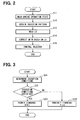
- FIG. 2 basic processing steps of fuel injection control according to the present embodiment will be explained. Values of various parameters used in the processing in FIG. 2 are stored as needed in memory devices such as the RAM, the EEPROM or the backup RAM mounted in the ECU 50 and are updated at any time when needed.
- the series of the processes in each figure is sequentially executed at each predetermined crank angle or in a predetermined time cycle for each cylinder of the engine 10 by executing programs stored in the ROM with the ECU 50.
- an injection pattern is set based upon the engine operating condition read at S11 or an accelerator pedal depressing amount provided by a driver (or by separately calculating a request engine operation state if necessary).
- the injection pattern is obtained based upon a certain map or the like (for example, stored and held in ROM 64).
- an optimal pattern (adapted value) is obtained by experiments or the like concerning each engine operating condition assumed beforehand.
- a relation between the engine operating condition and the optimal pattern is written in a map (or is defined with a mathematical expression).
- the injection pattern is defined by parameters such as an injection stage number (injection time number), injection timing, an injection period and an injection interval (injection interval in a case of a multiple injection).
- the optimal pattern (adapted value) is set to satisfy a request engine operating condition in accordance with an engine operating condition at each time (obtained at S11).
- the injection quantity (injection period) in a case of the single stage injection or a sum of injection quantities of respective injections in a case of the injection pattern of the multiple injection is variably set in accordance with the request torque or the like.
- a command value (command signal QFIN) to the injector 19 is set based upon the injection pattern.
- the aforementioned pre-injection, the pilot injection, the after injection, the post-injection or the like is performed with the main injection in accordance with a state of the vehicle.
- a correction coefficient LV updated by a separate learning processing is read out from the EEPROM 66 and then, at S14, a command value (command signal QFIN) to the injector 19 is corrected based upon the read correction coefficient LV.
- command values concerning the injection stage number, the injection timing, the injection period, the injection interval and the like are determined based upon the corrected command value (command signal QFIN) and the drive of the injector 19 is controlled based upon the command values.
- a learning mode (updating mode) of the correction coefficient LV used at S14 in FIG. 2 will be described in detail.
- Values of various parameters used in the series of the processes shown in FIGS. 3, 4, 10 and 11 are stored as needed in the memory devices such as the RAM, the EEPROM or the backup RAM mounted in the ECU 50 and are updated at any time when needed.
- the series of the processes in each figure is sequentially executed at each predetermined crank angle or in a predetermined time cycle for each cylinder of the engine 10 basically by executing programs stored in the ROM with the ECU 50.
- the processing of learning (updating) the correction coefficient LV by the device of the present embodiment is basically composed of the following two processing.
- FIGS. 3 and 4 are flowchart showing the process steps of the learning processing.
- an execution condition learning execution condition
- the learning processing Only when the execution condition is satisfied, the learning processing as a series of the processes shown in FIG. 4 is executed.
- process at S31 is repeated until the execution condition is satisfied.
- it is determined whether or not the execution condition is satisfied that is, whether or not the learning permission flag F is set at 1.
- the learning permission flag F is set at 1 by a series of the processes in FIG. 3 and S31 determines that the learning permission flag F is set at 1, the process goes to S32.
- the injection pattern is set based upon a certain table (one-dimensional map) or the like.
- an injection pattern (injection stage number (injection time number), injection timing, injection period, injection interval and the like) equal to (or corresponding to) an injection pattern (control map) used in control during a normal operation of the engine 10 is defined for each data number N (initial value is 1), for example. That is, in the first execution, the injection pattern of the data number 1 is set based on the table.
- the initial value of the counter M is 0.
- a predetermined threshold value SH for example, 10
- SH threshold value
- S36 it is determined that the value of the counter M is equal to or greater than the threshold value SH (M ⁇ threshold value SH) and the process goes to following S37.
- the fuel injections based on the respective injection patterns beforehand defined in a table are sequentially performed as described above.
- the sum (fluctuation parameter) of the fluctuation degrees of the engine operating condition due to all the injections (all injections during the pattern) for each injection pattern is obtained and stored with the injection condition (the data number N showing the injection pattern).
- FIGS. 5 and 6 are time chart illustrating an example of the injection pattern (INJ) set at S32 in FIG. 4 and transitions of the engine operating condition (NE) and the fluctuation parameter ( ⁇ NE) in the vicinity of the injection timing due to the injection pattern.
- each example detects the engine rotational speed NE as the engine operating condition.
- the injection illustrated in FIG. 5 is performed as the injection pattern of the data number 1
- the injection illustrated in FIG. 6 is performed as the injection pattern of the data number 2.
- this injection pattern is a single stage injection of a small quantity of fuel with one injection stage.
- the fuel of a quantity (injection quantity) shown by a region R1 in the injection rate characteristic R is injected.
- the injection rate characteristic R is not measured in the actual engine control.
- the injection rate characteristic is necessary, it can be estimated based upon, for example, the command signal QFIN.
- the injection rate characteristic is possible to directly determine the injection rate characteristic R including actual injection start timing and injection end timing with a higher accuracy.
- a movement delay of the injector 19 occurs. That is, a certain delay occurs from timing of the command (a rise edge or a decay edge of the pulse QFIN shown in FIG. 5) to timing of start or completion of the fuel injection movement of the injector 19 (execution or stop of the fuel injection shown in the injection rate R of FIG. 5).
- the engine rotational speed NE changes (fluctuates) from a value as of non-injection shown by a broken line L3a in FIG. 5 to a value shown by a solid line L3.
- a fluctuation mode of the engine rotational speed NE is shown as a transition of a sum (fluctuation parameter ⁇ NE) of fluctuation degrees of the engine rotational speed NE due to this injection.
- a positive fluctuation arises to the engine rotational speed NE as of the non-injection that has been stable during the deceleration. That is, a fluctuation from a value as of the non-injection shown by a broken line L4a in FIG. 5 to a value shown by a solid line L4 occurs.
- FIG. 6 shows an injection command and R shows an injection rate.
- ⁇ ne in FIG. 6 shows an influence (surge characteristic) applied by the former injection to the fluctuation degree (fluctuation amount) of the engine operating condition caused by the later injection in the multi injection in a time chart.
- this injection pattern is a multiple injection of two stages of fuel injections of small quantities.
- the former stage injection and the latter stage injection are performed during one combustion cycle (period of 720°CA).
- the injection interval between the both injections is set at an injection interval IBL as shown in FIG. 6.
- the injection rate characteristic R shown by the solid line L12 in FIG. 6 is obtained.
- the fuel of a quantity (injection quantity) shown by regions R11 and R12 in the injection rate characteristic R is injected as the injections of the former stage and the latter stage.
- the movement delay in the injector 19 occurs also on the occasion of injections in the former stage and the latter stage.
- the engine rotational speed NE changes (fluctuates) from a value as of non-injection shown by a broken line L13a in FIG. 6 to a value shown by a solid line L13.
- a fluctuation mode of the engine rotational speed NE is shown as a transition of a sum (fluctuation parameter ⁇ NE) of fluctuation degrees of the engine rotational speed NE due to all the injections (injections of the former stage and the latter stage) included in the injection pattern.
- the characteristic shown in FIG. 6, that is, a shift amount or a shift direction (positive side or negative side) of the latter stage injection characteristic due to the former stage injection changes in accordance with the injection timing (start and end), the injection period, the injection interval and the like of the both injections (injections of the former stage and the latter stage).
- FIG. 7 shows combustion cycles of the cylinders #1 to #4 and transitions of the position of the crankshaft 15 and the engine rotational speed NE accompanying the progress of the combustion cycles. Since the execution of the learning processing assumes the state of the fuel cut (non-injection), the combustion stroke is omitted in FIG. 7. In FIG. 7, reduction of the engine rotational speed NE due to the fuel cut is ignored for explanatory convenience. As shown in FIG.
- a combustion cycle consisting of four strokes of an intake stroke (INTA), a compression stroke (COMP), a combustion stroke and an exhaust stroke (EXHA) is sequentially performed in 720°CA cycle.
- FIGS. 8 and 9 are time charts each showing transitions of the engine rotational speed NE and the fluctuation degree thereof (fluctuation parameter ⁇ NE) before and after performing the fuel injection at S33 of FIG. 4.
- the transition of the engine rotational speed NE including a reduction amount of the engine rotational speed NE due to the fuel cut is shown.
- Each of timings shown by #1 and #3 in each figure shows TDC (top dead center) of each of the first and third cylinders.
- the engine rotational speed NE at each time is detected at 720°CA cycle.
- the engine rotational speeds NE(t21), NE(t22), NE(t23), NE(t24) are obtained and the fluctuation parameter ⁇ NE at each time is calculated based upon the engine rotational speed NE at each time.
- the engine rotational speed NE at each time can be sequentially detected based upon the rotational speed of the crankshaft 15 detected by the crank angle sensor 41, for example.
- the engine rotational speed NE can be also detected with high accuracy by the rotational speed of the camshaft 16 detected by the cam angle sensor 42.
- the engine rotational speed NE is sequentially (in 720°CA cycle) detected based upon either one (or both) of the rotational speed of the crankshaft 15 and the rotational speed of the camshaft 16.
- the detection timing of the engine rotational speed NE is reached is determined based upon the rotational angle of the valve operating camshaft 16 rotating in synchronization with the movement of the intake valve 161 (or exhaust valve) of the engine 10 or the rotational angle of the crankshaft 15 linked with the valve operating camshaft 16. Based upon this determination, the engine rotational speed NE at the time when it is determined that the detection timing of the engine rotational speed is reached is detected.
- the aforementioned injection (at S33 of FIG. 4), that is, the fuel injection to the first cylinder #1, is performed at timing t23a immediately before the timing t23.
- the injection timing t23a in this example corresponds to the TDC of the first cylinder #1 as the object of the injection.
- the injection start timing t1 is set so that an actual injection start is close to the TDC in consideration of the movement delay of the injector 19.
- the injection start timing t14 is set so that the injection start of the latter stage injection (corresponding to the injection of the final stage) is close to the TDC.
- the transition of the engine rotational speed NE after the timing t23a is shown not by a graph as of the non-injection shown in FIG. 8 (i.e., graph shown by a chain double-dashed line L22 in FIG. 9) but by a graph shown by a solid line L21 in FIG. 9, that is, a graph reflecting the influence of the injection.
- the engine rotational speeds NE (t21), NE (t22), NE (t23), NE (t24) at the timings t21, t22, t23, t24 are obtained in accordance with the graph shown by the solid line L21 in FIG. 9.
- the fluctuation parameter ⁇ NE in the 720°CA cycle is calculated in accordance with a following expression (Formula 1) based upon the obtained engine rotational speed NE at each time.
- ⁇ NE ⁇ NE ⁇ 2 ⁇ a - ⁇ NE 2 ⁇ [ ( ⁇ NE ⁇ 1 + ⁇ NE ⁇ 3 ) / 2 ] - ⁇ NE ⁇ 2
- the fluctuation degrees ⁇ NE1, ⁇ NE2, ⁇ NE2a, ⁇ NE3 of the engine rotational speed NE are defined by the engine rotational speed NE'(t23) and the above-described engine rotational speeds NE(t21) - NE(t24) according to the following expression (Formula 2).
- ⁇ NE ⁇ 1 NE ( t ⁇ 21 ) - NE t ⁇ 22
- ⁇ NE ⁇ 2 NE ( t ⁇ 22 ) - NE t ⁇ 23
- ⁇ NE ⁇ 2 ⁇ a NE ( t ⁇ 22 ) - NE ⁇ t ⁇ 23
- ⁇ NE ⁇ 3 NE ( t ⁇ 23 ) - NE t ⁇ 24 ,
- the engine rotational speed NE'(t23) corresponds to the engine rotational speed NE at the timing t23 in the case of the non-injection (shown by chain double-dashed line L22) and is set virtually for approximately calculating the fluctuation parameter ⁇ NE.
- the fluctuation parameter ⁇ NE due to the injection performed at S33 of FIG. 4 is calculated as the difference (NE(t23) - NE'(t23)) between the actual engine rotational speed NE(t23) (shown by solid line L21) at the rotational speed detection timing t23 immediately after the injection and the engine rotational speed NE'(t23) in the case of the non-injection (shown by chain double-dashed line L22).
- the engine rotational speed NE'(t23) is approximately calculated (estimated) by using the fluctuation degree ⁇ NE1 of the engine rotational speed NE in the combustion cycle before the injection and the fluctuation degree ⁇ NE3 of the engine rotational speed NE in the combustion cycle after the injection (as shown by Formula 1).
- the thus-obtained fluctuation parameter ⁇ NE is converted into an energy equivalent according to Formula 3 to obtain the fluctuation parameter as an energy value (fluctuation parameter ⁇ E).
- I denotes an inertia moment and is basically defined by a design value of the engine 10 (particularly, flywheel or the like).
- ⁇ NE/ ⁇ t corresponds to a value obtained by second order differential of an angular velocity ⁇ (engine rotational speed NE) as of the injection.
- ⁇ t corresponds to the time from injection timing t23a to the rotational speed detection timing t23 immediately after the injection. Accordingly, in this example, the time ⁇ t is obtained as the time necessary for the crankshaft 15 to rotate by 180°CA from the TDC of the first cylinder #1 to the TDC of the third cylinder #3. That is, the time ⁇ t can be expressed by following Formula 4 by using the engine rotational speed NE as of the injection.
- the engine rotational speed NE at each time is detected in the 720°CA cycle.
- the injection is performed in the mode of each of FIGS. 5 and 6 and at following S34, the fluctuation parameter of each injection pattern shown in each of FIGS. 5 and 6 is calculated.
- the fluctuation parameter ⁇ NE is obtained based upon the fluctuation degrees ⁇ NE1 to ⁇ NE3 of the engine rotational speed NE at each time detected in the cycle of 720°CA.
- the fluctuation parameter ⁇ NE is converted into the energy equivalent to obtain the fluctuation parameter ⁇ E as the energy value.
- a sum of the fluctuation degrees (fluctuation parameter ⁇ E) of the engine operating condition due to all the injections (one injection in the case of the data number 1, and two injections in the case of the data number 2) is repeatedly obtained for each injection pattern (data number 1 or 2).
- the fluctuation parameters ⁇ E of the number of the threshold values SH presented in FIG. 4 (for example, 10 pieces of the fluctuation parameters ⁇ E) are stored in the EEPROM 66 together with the data number N (1 or 2).
- the fluctuation parameters ⁇ E are obtained for each of the cylinders #1 to #4 and are managed individually (to be distinguishable) for each cylinder (cylinder number). More specifically, for example, the fluctuation parameters ⁇ E are classified and stored in memory regions (for example, plural memory devices or plural regions in a single memory device) prepared for the respective cylinder numbers so that each data is managed to be distinguishable.
- FIGS. 10 and 11 are flowcharts each showing process steps of the correction processing. Also in each processing, as in the case of the processing of FIG. 4, first, it is determined whether or not an execution condition concerning the correction processing (correction execution condition) is satisfied. Only when the execution condition is satisfied, a series of processes shown in each figure is executed.
- an execution condition concerning the correction processing correction execution condition
- the correction processing (correction I) will be explained in detail by referring to FIG. 10.
- S41 it is determined whether or not the aforementioned execution condition is satisfied.
- S42 This execution condition may be arbitrarily set.
- the execution condition is that the data used for the correction (i.e. for updating of the correction coefficient) such as the fluctuation parameters ⁇ E (hereinafter, referred to as data A and data B) of the injection patterns corresponding to the data numbers 1, 2 (equivalent to first injection unit and second injection unit) are stored in the EEPROM 66.
- data A and data B fluctuation parameters ⁇ E
- the correction processing of S42 and subsequent steps after S41 is executed if the data A, B are stored in the EEPROM 66.
- the data A, B (fluctuation parameters ⁇ E) are read from the EEPROM 66.
- each data are obtained to the number equal to the threshold value SH (FIG. 4). Therefore, an average value of each of the data A, B is obtained as a final value. For example, when ten data A (or ten data B) are obtained, a sum of the ten data A (or ten data B) is divided by ten to obtain the average value.
- each of the final single data A, B is converted into a value per a predetermined unit injection number (unit injection stage number). For example, in the case of setting the unit injection number at one, the data A corresponding to the single stage injection (shown in FIG. 5) is kept as it is, and the data B corresponding to the multiple injection of two stages (shown in FIG. 6) is multiplied by 1/2 to obtain the fluctuation parameter ⁇ E per one time (one stage).
- the correction coefficient used at S14 of FIG. 2 is updated based upon the deviation degree ⁇ K obtained at S44.
- the correction coefficient of the injection pattern (the multiple injection of the two stages) corresponding to the data number 2 is updated (changed) to conform the data B (data number 2) to the data A (data number 1) on a basis of the data A (data number 1).
- the deviation degree ⁇ K is basically proportional to a deviation degree ⁇ Q in the injection quantity between the injection patterns of the data number 1 and the data number 2 ( ⁇ K ⁇ ⁇ Q). Therefore, on the occasion of updating the correction coefficient, in order to compensate the deviation in the injection quantity between the injection patterns (deviation degree ⁇ Q), the injection quantity is corrected (increased or decreased) by, for example, changing the correction coefficient concerning the injection period (equivalent to energization period of the injector 19).
- the targeted engine operating condition can be obtained through the multiple injection with high accuracy.
- the above-described correction example is only one of examples.
- the object to be corrected is not limited to the injection period (energization period).
- the injection quantity can be also changed by the injection start timing or the injection end timing.
- the injection quantity can be changed by changing the injection start timing.
- the injection start timing is constant, the injection quantity can be changed by changing the injection end timing.
- the injection timing (start/end), the injection period, the injection interval and the like may be corrected to compensate the influence (surge characteristic) of the former stage injection shown in FIG. 6. Also in such the manner, the engine operating condition can be approximated to the target sttate (i.e., accuracy in control can be improved).
- the injection pattern of the data number 1 is corrected with respect to a certain reference value, and then, the injection pattern of the data number 2 is corrected with respect to the corrected injection pattern.
- the fluctuation degree ⁇ NE of the engine rotational speed NE occurs as shown by the solid line L4 with respect to the engine rotational speed NE (shown by the broken line L4a in FIG. 5) that has been stable during the decelerating operation.
- the fluctuation degree ⁇ NE of the engine rotational speed NE is detected and calculated according to formula 1 and formula 3 and is finally obtained as the fluctuation parameter ⁇ E, which is the energy value.
- the fluctuation parameter ⁇ E (data B) is read out from the EEPROM 66 at S42.
- a certain reference value (data A) as shown by a dashed line L4b in FIG. 5 is also read out from, for example, the ROM 64.
- a predetermined value (adapted value) beforehand determined from, for example, experiments or the like may be used as the reference value (data A).
- the correction coefficient LV of the injection pattern concerning the data number 1 is updated based upon the deviation degree ⁇ K1.
- the injection period from the timing t1 to the timing t2 is corrected to the injection period from the timing t1 to timing t2a as shown by a broken line L1a in FIG. 5.
- the injection rate characteristic R and eventually the injection quantity can be increased as shown by a broken line L2a in FIG. 5.
- a region R1a in Fig. 5 shows an increase of the injection quantity due to the correction.
- the correction is performed with respect to the corrected injection pattern in the data number 1. That is, the injections in the injection pattern concerning the data number 2 are performed after the correction of the injection pattern of the data number 1.
- the fluctuation parameter ⁇ E (data B) due to the former stage injection and the latter stage injection shown in FIG. 6 is read out from the EEPROM 66.
- the data after the correction of the injection pattern of the data number 1 i.e., fluctuation parameter ⁇ E corresponding to correction coefficient
- the data (data A) after the correction corresponds to a fluctuation parameter ⁇ NE (converted into a fluctuation parameter ⁇ E) shown by a dashed line L14b in FIG. 6.
- the data A and the data B as average values respectively are converted into the values per a certain unit injection time number.
- two times is used as the unit injection time number.
- the data A concerning the single stage injection the data A is multiplied by two to obtain the fluctuation parameter ⁇ E per two times of the injections.
- the data A becomes a value corresponding to the fluctuation parameter ⁇ NE shown by a dashed line L14c in FIG. 6.
- the data B concerning the multiple injection as the two stage injection is kept as it is.
- the correction coefficient LV of the injection pattern concerning the data number 2 is updated based upon the deviation degree ⁇ K2.
- the injection period from the timing t14 to the timing t15 is corrected to an injection period from the timing t14 to timing t15a as shown by a broken line L11a in FIG. 6.
- the injection rate characteristic R and eventually the injection quantity can be increased as shown by a broken line L12a in FIG. 6.
- a region R12a in FIG. 6 shows an increase quantity of the injection quantity due to the correction.
- the fluctuation parameters ⁇ E (data A, B) of the injection pattern of the corrected data number 1 and the injection pattern of uncorrected data number 2 are obtained.
- the data B multiple injection
- the relative correction of the data B is performed based upon the corrected data A containing a small error with respect to a true value. Therefore, in regard to the data B also, an error with respect to a true value (absolute deviation degree) is indirectly compensated.
- another injection pattern for example, three stage injection as a multiple injection
- FIG. 11 in a series of processes, first at S51, it is determined whether or not the aforementioned execution condition is satisfied. When S51 is YES, the process goes to S52.
- the process at S 51 is similar to the process at S41 in FIG. 10.
- the execution condition is satisfied when multiple kinds of injection patterns, which are different from the injection pattern of the data number 2 only in the injection interval IBL, i.e., which are different from each other only in the injection interval IBL, are obtained to a certain number (for example, 18 pieces as shown in FIGS. 12A to 12C) in addition to the injection patterns of the data number 1 and the data number 2.
- These injection patterns are obtained as the data numbers 3, 4, 5, etc. to follow the data numbers 1, 2 by the processing (learning processing) in FIG. 4 like the injection patterns of the data number 1 and the data number 2 and are stored in the EEPROM 66.
- the fluctuation parameters ⁇ E due to the injection patterns of the data numbers 1, 2 are read out as the data A, B.
- arbitrary conversion processing as processing before comparison is applied to the fluctuation parameters ⁇ E.
- the deviation degree ⁇ K concerning the converted values is calculated and obtained.
- a waveform (waveform information) showing a relation between the deviation degree ⁇ K obtained at S52 and the injection interval of the second injection unit is obtained based upon the deviation degree ⁇ K (all of the deviation degrees ⁇ K when there are a plurality of them).
- it is determined whether or not the aimed waveform information is obtained by the process at S53.
- the deviation degree ⁇ K of the fluctuation parameters ⁇ E conversion value
- S54 is YES (i.e., the aimed waveform information is obtained)
- the processes at S51 to S53 are repeatedly executed.
- S54 is YES (i.e., the aimed waveform information is obtained)
- a phase deviation and a cycle deviation from a predetermined reference waveform are calculated based upon the waveform information.
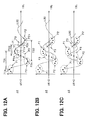
- FIGS. 12A to 12C are time charts each showing a relation between the fluctuation parameter ⁇ E (longitudinal axis) and the injection interval IBL (lateral axis) concerning the second injection unit (injection patterns of the data numbers 2, 3, 4, 5, etc.).
- a waveform shown by a dashed line L30 is a certain waveform (reference waveform) as a reference of a change mode of the fluctuation degree (a sum of fluctuation degrees due to former stage injection and latter stage injection) of the engine operating condition corresponding to the injection interval.
- the reference waveform is beforehand stored in an arbitrary memory device such as the ROM 64 or the EEPROM 66.
- a plurality of kinds of injection intervals IBL of the second injection unit (each of injection patterns concerning the data numbers 2, 3, 4, 5, etc.) read out at S52 are set at certain portions in a concentrated manner.
- the injection intervals IBL contain only injection intervals corresponding to portions (positive-side peak portion P1, negative-side peak portion P2 and node portion P3) showing regularity of the reference waveform (dashed line L30).
- Such the data can be obtained by beforehand writing such injection patterns in the table used at S32 in FIG. 4, for example.
- a waveform showing a relation between the deviation degree ⁇ K which is obtained by comparing the fluctuation parameter ⁇ E of the first injection unit (injection pattern concerning the data number 1) and each fluctuation parameter ⁇ E of the second injection unit (each of injection patterns concerning the data numbers 2, 3, 4, 5, etc. ), and the injection interval IBL of the second injection unit is calculated based upon each deviation degree ⁇ K.
- the aimed waveform information i.e., measured waveform
- the measured waveform shows an injection characteristic of the fuel supply system (particularly, injector 19) in the system (FIG. 1) at each time, including the aging characteristic change.
- the phase deviation ⁇ P and the cycle deviation ⁇ C between the measured waveform and the reference waveform are calculated based upon the waveform information obtained At S54.
- the phase deviation ⁇ P of the measured waveform from the reference waveform is obtained based upon the deviation degree ⁇ K. That is, positions (injection intervals) of positive-side peaks P1a, P1b of the measured waveform are detected as points where the deviation degree ⁇ K is maximized. Positions (injection intervals) of negative-side peaks P2a, P2b of the measured waveform are detected as points where the deviation degree ⁇ K is minimized. In addition, positions (injection intervals) of nodes P3a, P3b of the measured waveform are detected as points where the deviation degree ⁇ K is zero.
- each position (each injection interval) of the positive-side peaks P1a, P1b, the negative-side peaks P2a, P2b and the nodes P3a, P3b is compared with each corresponding position of the reference waveform (for example, the difference is calculated).
- the phase deviation ⁇ P of the measured waveform from the reference waveform is obtained.
- a relation between the measured waveform and the reference waveform (dashed line L30) in the case where the phase deviation between waveforms occurs is shown in FIG. 12B.
- the cycle deviation ⁇ C of the measured waveform from the reference waveform is obtained based upon the deviation degree ⁇ K.
- an interval T33 between the nodes P3a, P3b is obtained based upon positions (i.e., injection intervals IBL) of the detected nodes P3a, P3b.
- an interval T31 between the positive-side peaks P1 a, P1b, and an interval T32 between the negative-side peaks P2a, P2b are obtained.
- Each of the intervals T31, T32, T33 corresponds to a cycle of the measured waveform.
- each of the intervals T31, T32, T33 (or an average value of the intervals) is compared with each corresponding cycle of the reference waveform (or the corresponding average value) (for example, a difference is calculated).
- the cycle deviation ⁇ C of the measured waveform from the reference waveform is obtained.
- a relation between the measured waveform and the reference waveform (dashed line L30) in the case where the cycle deviation occurs between the waveforms is shown in FIG. 12C, for example.
- phase deviation ⁇ P and the cycle deviation ⁇ C between the measured waveform and the reference waveform are respectively calculated and obtained in the above described modes.
- the correction coefficient LV used at S14 in FIG. 2 is updated based upon the phase deviation ⁇ P and the cycle deviation ⁇ C.
- the correction coefficient concerning at least one of the injection start timing t14, the injection end timing t15 and the injection interval IBL of each of the injection patterns (two stage injection as the multiple injection, e.g., shown in FIG. 6) of the data numbers 2, 3, 4, 5, etc. is updated.
- the target engine operating condition can be obtained with high accuracy through the multiple injection.
- This correction example is one of the examples, and the object of the compensation or the correction herein is not limited to the above-described parameters.
- a correction coefficient concerning the above-described injection parameter or other parameters such as the injection period may be updated (corrected) to compensate an amplitude deviation of the measured waveform from the reference waveform based upon at least one of the positive peak position and negative peak position of the measured waveform detected at S55.
- the engine operating condition can be approximated to the target condition (i.e., control accuracy is improved).
- the injection characteristic (fluctuation parameter ⁇ E) at each time including the aging characteristic change is learned by the learning processing shown in FIGS. 3 and 4 in series.
- at least one of two kinds of correction processing (correction I and correction II) shown in FIGS. 10 and 11 is executed.
- the certain correction coefficient is updated based upon the learned value (injection characteristic) and at the same time, the correction concerning the fuel injection is performed by using the correction coefficient at S13 and S14 of FIG. 2. That is, in the present embodiment, it is possible to obtain the correction coefficient at each time as the injection characteristic at each time concerning the fuel supply system by the fuel injection controller and the diagnosis method of the fuel supply system. In addition, it is possible to more accurately correct a control error due to the aforementioned individual difference, the aging change or the like by using the correction coefficient.
- the fuel injection controller and the diagnosis method of the fuel supply system according to the present embodiment can achieve following excellent effects, for example.
- the present embodiment may be modified as follows, for example.
- the diagnosis of whether or not the fuel supply system of the engine 10 operates normally may be enabled more positively or may be actually performed automatically based upon the deviation degree ⁇ K or the correction coefficient obtained by the above-described method.
- failsafe processing or the like may be executed based upon the magnitude of the deviation degree ⁇ K or the correction coefficient.
- the correction coefficient is less than a predetermined value, as in the case of the above, the correction is performed based upon the correction coefficient.
- arbitrary warning processing such as turning-on of a warning lamp may be executed to urge a user to replace the injector 19 or the like.
- the deviation degree ⁇ K or the correction efficient may be constantly (or in an arbitrary period) displayed in a visible place in a vehicle so that the user can confirm a performance degradation degree of the fuel supply system at each time.
- this scheme it is possible to early and properly detect the injection characteristic (particularly, injection characteristic of the multiple injection), correct the injection characteristic, and replace the injector 19 or the like.
- plural fluctuation parameters ⁇ E are obtained at a stage before comparison and the final fluctuation parameter ⁇ E is obtained as the average value.
- plural deviation degrees ⁇ K may be obtained by plural times of comparisons and a final deviation degree ⁇ K may be obtained as an average value. Also in this case, an effect similar to or corresponding to the effect (2) can be obtained.
- the injection rate (fuel quantity injected per unit time) may be corrected as a parameter of the injection quantity.
- the injection rate can be varied by using a direct operating injector (for example, a direct operating piezo injector) for transmitting drive power not through a hydraulic chamber in place for the electromagnetic drive injector 19. Also in this case, an effect similar to or corresponding to the effect (7) can be obtained.
- the present embodiment assumes employment of the adaptation map (S11 in FIG. 2) for beforehand defining the adapted value by experiments or the like and stores the correction coefficient for correcting the injection characteristic by the adaptation map in the EEPROM 66 capable of holding the correction coefficient in the nonvolatile state.
- a value after correction value reflecting the correction coefficient
- a so-called non-adaptation scheme may be adopted, which does not require the adaptation map, as long as the value after the correction is sufficiently reliable.
- a memory device such as another nonvolatile memory or backup RAM can be adopted as needed in place for the EEPROM. Also in this case, an effect similar to or corresponding to the effect (10) can be obtained.
- the present embodiment may be constructed to include a condition concerning the transmission as the execution condition (determined at S21 in FIG. 3) of the injections at S32 and 33 in FIG. 4. Also with this scheme, an effect similar to or corresponding to the effect (11) can be obtained. In this case, disturbances applied via the drive wheels from the road can be suppressed by performing the injection on a condition that the clutch is disengaged in the MT21 (manually operated transmission) even when the injection is performed during the operation of the vehicle including the controller (particularly, during the running). In a case of detecting the injection characteristic of the injector based upon the fluctuation parameter obtained by the injection, an error due to the disturbances from a road surface is reduced and therefore, more accurate detection can be performed.
- the controller of the present invention in a case of applying the controller of the present invention to an AT (automatic transmission) vehicle, it is effective to provide a construction that performs the injection on a condition that lockup of a torque converter (T/C) in the AT is in a disengaged state. Also in this case, an effect similar to the case of MT can be obtained.
- Such the condition concerning the transmission may be added to the aforementioned condition or may be used in place for the condition that the engine 10 is decelerating or the like. If the injection is performed by defining the condition concerning the transmission as the essential condition, the high detection accuracy is achieved but it becomes difficult to ensure sufficient frequency of the injection execution.
- condition concerning the transmission and the above-described other conditions in parallel (i.e., as OR conditions).
- condition that the engine 10 is decelerating or the clutch is in the disengagement state in the MT as one of the satisfaction requirements of the injection execution condition.
- the present embodiment assumes that the execution condition of the injections in S32 and 33 in FIG. 4 (determination in S21 in FIG. 3) is fixed.
- a program injection execution condition varying device
- the execution condition since the execution condition is varied, the execution condition can be varied to be applied to various applications more flexibly.
- the injection characteristic corresponding to the difference of the execution conditions (injection pressure, engine rotational speed or the like) can be easily detected.
- the present embodiment adopts the single stage injection shown in FIG. 5 as the first injection unit and the multiple injection of two stages shown in FIG. 6 as the second injection unit and compares the fluctuation parameters ⁇ E respectively caused by all the injections of the respective units.
- the first and second injection units are not limited to such the injection patterns but may be arbitrary as long as the injection pattern of the multiple injection is included in at least one of the first and second injection units. That is, either one or both of the first and second injection units may be constructed of a certain combination/combinations of the injection patterns.
- At S32 and S33 in FIG. 4, at least a first injection pattern of n stage(s) of a certain stage number composed of a single stage injection or a multiple injection, a second injection pattern of m stage(s) of a certain stage number composed of a single stage injection or a multiple injection and a third injection pattern composed of n + m stages of a multiple injection may be executed in a certain order.
- a fluctuation parameter ⁇ E may be obtained for each of a first injection unit composed of the combination of the first and second injection patterns and a second injection unit composed of the third injection pattern.
- a combination of the one-time injection pattern and the three-time injection pattern is set as the first injection unit and the four-time injection pattern is set as the second injection unit.
- a fluctuation degree ⁇ E11 energy conversion value
- a fluctuation degree ⁇ E13 three-time injection pattern
- a fluctuation degree ⁇ E24 four-time injection pattern
- the fluctuation parameter ⁇ E1 of the first injection unit is obtained as ⁇ E11 + ⁇ E13 and the fluctuation parameter ⁇ E2 of the second injection unit is obtained as ⁇ E24.
- the combination of certain injection patterns as one of the first injection unit and the second injection unit, it is possible to constitute a pair of the first and second injection units having the equal sums of the stage number of all the injection pattern(s) (i.e., the sum of the injection time number of the first injection unit is the same as the sum of the injection time number of the second injection unit).
- the present embodiment may be constructed so that two kinds of injection patterns different from each other in a parameter other than the injection time number (for example, the injection interval IBL, the injection start timing t14, the injection end timing t15, the injection period T12, the injection rate R (solid line L12) shown in FIG. 6 or the like) are set as the first and second injection units respectively.
- a fluctuation parameter ⁇ E or a deviation degree ⁇ K concerning the parameter may be obtained, and further, detection or correction of the injection characteristic and the like concerning the parameter may be performed.
- a deviation degree of the injection period or the injection quantity is obtained based upon the above-described fluctuation parameter ⁇ E or the deviation degree ⁇ K.
- the fuel quantity is controlled to be low to restrict deterioration of drivability and at the same time, at least a deviation degree in one direction (positive side in the injection quantity) of the injection characteristic concerning the injection period (eventually, injection quantity) can be accurately detected.
- this scheme is not suitable for an application for detecting a deviation degree in both directions of the injection characteristic concerning the injection period (eventually, injection quantity).
- the present embodiment adopts all of the positive-side peak portion P1, the negative-side peak portion P2 and the node portion P3 as the portions showing the regularity of the reference waveform (dashed line L30 in FIGS. 12A to 12C), but it is sufficient only to adopt at least one of them.
- the portion showing the regularity is not limited to these portions, but for example, a point between the positive-side peak portion P1 and the node portion P3 (for example, intermediate point) may be adopted.
- an injection interval other than the portion showing the regularity may be included in the intervals of the second injection unit read at S52 in FIG. 11 on the occasion of obtaining the waveform (waveform information) of the injection characteristic illustrated in FIGS. 12A to 12C.
- the present embodiment may be constructed so that providing a band pass filter (for example, band filter composed of a known transfer function) having a passing band corresponding to the detection timing of the engine rotational speed (S34 in FIG. 4) for the sensor output of the rotational speed sensor (crank angle sensor 41 or cam angle sensor 42), for example.
- a band pass filter for example, band filter composed of a known transfer function
- the rotational speed of the engine is detected at certain timing through the band pass filter.
- the present embodiment is constructed so that the rotational speed of the engine is detected in a certain rotational angle cycle by using the electromagnetic pickup type rotational speed sensor.
- a linear detection type rotational speed sensor for linearly (that is, continuously) detecting a rotational position of the crankshaft may be used.
- a resolver is known as the linear detection type rotational speed sensor.
- a sum of the fluctuation degrees in the engine operating condition due to all the injections in each of the first and second injection units is detected at a time.
- a fluctuation degree in the engine operating condition due to each injection for example, each of the former stage injection and the latter stage injection of the multiple injection shown in FIG. 6
- the fluctuation degrees may be added for each injection unit to obtained a sum due to all the injections.
- the fluctuation parameter corresponding to each injection unit can be obtained.
- a method (construction) of arbitrarily changing the above-described method (construction) in accordance with an application may be adopted.
- the present embodiment may use a parameter other than the injection time number as a comparison condition and may include a program (conversion device) for converting the fluctuation parameter ⁇ E (comparison data) of each injection unit obtained by the process at S34 in FIG. 4 to be suitable for the comparison condition.
- a program conversion device
- one of the values to be compared may be multiplied by a certain magnification ratio before the comparison to eliminate an influence other than the parameter as the comparison object. This enables more accurate comparison. For example, in a case of comparison concerning the injection period, it is effective to eliminate the influence of other parameters such as the injection interval (increasing/decreasing amount applied to the fluctuation parameter ⁇ E).
- the conversion of the fluctuation parameter ⁇ E before the comparison is not an essential element. In an application that does not require the conversion, the conversion can be eliminated. For example, there is a case where a fluctuation parameter ⁇ E before comparison is obtained without automating conversion processing or comparison processing and a user performs the conversion. Further, there is a case where as a result of a combination of the first and second injection units, comparison conditions of the fluctuation parameters ⁇ E coincide with each other at the time of obtainment thereof. In such the cases, the conversion can be omitted.
- the present embodiment may be constructed so that, a fluctuation parameter ⁇ E before the comparison is obtained at S34 in FIG. 4 and a user performs the comparison without automating (for example, programming) the processes (process at S44 in FIG. 10 or S52 in FIG. 11) concerning the comparison and the obtainment of the deviation degree ⁇ K. In this case, all the processes concerning the correction shown in FIG. 10 or FIG. 11 can be eliminated. Even with this scheme, an effect similar to the effect (1) can be achieved.
- the conversion of the fluctuation degree of the engine operating condition (for example, engine rotational speed) into the energy equivalent (fluctuation parameter ⁇ E) is not an essential condition. In a case where sufficient detection accuracy can be obtained in accordance with an application or the like, this conversion processing (conversion processing by the formula 3) may be eliminated when needed.
- a combustion state (correlated with engine torque) detected by, for example, an in-cylinder pressure sensor, a knock sensor or the like may be used in addition to the aforementioned engine rotational speed.
- an equivalent of the engine operating condition indirectly showing the engine operating condition such as a quantity of a specific exhaust component (for example, NOx) detected by a proper sensor (for example, NOx sensor) or the like or a behavior of a vehicle (for example, vehicle speed) having the present engine may be used.
- a scheme of providing a program (in-cylinder pressure detection device) for detecting the pressure in the cylinder through the in-cylinder pressure sensor and obtaining the fluctuation parameter ⁇ E at S34 in FIG. 4 based upon the pressure inside the cylinder detected by the program achieves high accuracy in torque detection and specifically effective.
- the above-described plural parameters may be used in combination.
- the present embodiment refers to a case where the present invention is applied to the common rail system of the diesel engine as one example, but the present invention may be basically applied to a spark ignition type gasoline engine (particularly, direct injection engine) in the same way.
- a fuel injection controller (incorporated in an engine control ECU (50)) for controlling an injection operation of an injector (19) has a program (S32, S33) for executing injections in plural injection patterns including an injection pattern of a multiple injection in a certain order into a certain cylinder of the engine (10) during non-injection operation and a program (S34) for obtaining sums of fluctuation degrees of an engine operating condition due to all the injections in a first injection unit composed of one (single stage injection) of the plural patterns and all the injections in a second injection unit composed of a different one (multiple injection of two stages) of the plural patterns, which are executed by the former program (S32, S33), with an injection condition (cylinder number and data number N).
Landscapes
- Engineering & Computer Science (AREA)
- Chemical & Material Sciences (AREA)
- Combustion & Propulsion (AREA)
- Mechanical Engineering (AREA)
- General Engineering & Computer Science (AREA)
- Electrical Control Of Air Or Fuel Supplied To Internal-Combustion Engine (AREA)
- Combined Controls Of Internal Combustion Engines (AREA)
- Control Of Vehicle Engines Or Engines For Specific Uses (AREA)
Applications Claiming Priority (1)
| Application Number | Priority Date | Filing Date | Title |
|---|---|---|---|
| JP2006294776A JP4899791B2 (ja) | 2006-10-30 | 2006-10-30 | 燃料噴射制御装置及び燃料供給系の診断方法 |
Publications (2)
| Publication Number | Publication Date |
|---|---|
| EP1918558A1 true EP1918558A1 (fr) | 2008-05-07 |
| EP1918558B1 EP1918558B1 (fr) | 2017-12-27 |
Family
ID=39135132
Family Applications (1)
| Application Number | Title | Priority Date | Filing Date |
|---|---|---|---|
| EP07119304.9A Ceased EP1918558B1 (fr) | 2006-10-30 | 2007-10-25 | Contrôleur d'injection de combustible et procédé de diagnostic d'un système d'alimentation en carburant |
Country Status (4)
| Country | Link |
|---|---|
| US (1) | US8010277B2 (fr) |
| EP (1) | EP1918558B1 (fr) |
| JP (1) | JP4899791B2 (fr) |
| CN (1) | CN101173638B (fr) |
Cited By (1)
| Publication number | Priority date | Publication date | Assignee | Title |
|---|---|---|---|---|
| EP2469064A1 (fr) * | 2010-12-24 | 2012-06-27 | Delphi Technologies, Inc. | Procédé pour contrôler un moteur à combustion interne |
Families Citing this family (32)
| Publication number | Priority date | Publication date | Assignee | Title |
|---|---|---|---|---|
| JP2006291755A (ja) * | 2005-04-06 | 2006-10-26 | Denso Corp | 燃料噴射制御装置 |
| JP3904022B2 (ja) * | 2005-08-18 | 2007-04-11 | いすゞ自動車株式会社 | 燃料噴射制御システム |
| DE102007003150B4 (de) * | 2007-01-22 | 2008-12-11 | Continental Automotive Gmbh | Verfahren zur Ermittlung einer unkontrollierten Drehzahlerhöhung einer Brennkraftmaschine |
| US7706957B2 (en) | 2007-08-30 | 2010-04-27 | Denso Corporation | Apparatus for controlling quantity of fuel to be actually sprayed from injector in multiple injection mode |
| JP4479764B2 (ja) | 2007-08-31 | 2010-06-09 | 株式会社デンソー | 燃料噴射制御装置およびそれを用いた燃料噴射システム |
| DE102007042994A1 (de) * | 2007-09-10 | 2009-03-12 | Robert Bosch Gmbh | Verfahren zum Beurteilen einer Funktionsweise eines Einspritzventils bei Anlegen einer Ansteuerspannung und entsprechende Auswertevorrichtung |
| JP5245517B2 (ja) * | 2008-04-28 | 2013-07-24 | いすゞ自動車株式会社 | エンジンの燃料噴射制御装置 |
| KR20090126619A (ko) * | 2008-06-04 | 2009-12-09 | 현대자동차주식회사 | 차량의 씨 디 에이 장치 진단시스템 및 그 방법 |
| DE102008040626A1 (de) * | 2008-07-23 | 2010-03-11 | Robert Bosch Gmbh | Verfahren zur Bestimmung der eingespritzten Kraftstoffmasse einer Einzeleinspritzung und Vorrichtung zur Durchführung des Verfahrens |
| JP4414470B1 (ja) * | 2008-10-10 | 2010-02-10 | 本田技研工業株式会社 | 車両の故障診断のための基準値の生成 |
| DE102008042933B4 (de) * | 2008-10-17 | 2016-06-16 | Hyundai Motor Company | Verfahren und Vorrichtung zum Dosieren von in einen Brennraum eines Verbrennungsmotors einzuspritzendem Kraftstoff |
| JP2011052670A (ja) * | 2009-09-04 | 2011-03-17 | Denso Corp | 内燃機関の燃料噴射装置 |
| WO2011048676A1 (fr) * | 2009-10-21 | 2011-04-28 | トヨタ自動車株式会社 | Dispositif de commande de combustion pour moteur à combustion interne |
| US20110213544A1 (en) * | 2010-02-26 | 2011-09-01 | Denso Corporation | Fuel injection controller for internal combustion engine |
| DE102010063344B4 (de) * | 2010-12-17 | 2023-03-23 | Robert Bosch Gmbh | Verfahren zum koordinierten Durchführen einer Anzahl von Injektorkalibrierungsvorgängen |
| JP5938955B2 (ja) * | 2012-03-09 | 2016-06-22 | トヨタ自動車株式会社 | 内燃機関の燃料噴射特性学習装置 |
| JP5546595B2 (ja) * | 2012-08-07 | 2014-07-09 | 三菱電機株式会社 | 内燃機関のノック制御装置 |
| DE102013108187A1 (de) * | 2012-12-05 | 2014-06-05 | Hyundai Motor Company | Kraftstoffverteiler für einen Motor mit doppelten Einspritzdüsen und Verfahren zur Steuerung des Kraftstoffverteilers |
| US20140172277A1 (en) * | 2012-12-18 | 2014-06-19 | Caterpillar Inc. | Engine diagnostic system and method |
| US9435310B2 (en) * | 2013-03-07 | 2016-09-06 | Cummins Inc. | Hydraulic start-of-injection detecting system and method |
| JP2015121132A (ja) * | 2013-12-24 | 2015-07-02 | ボッシュ株式会社 | ディーゼルエンジンの最小燃料噴射間隔設定方法及びコモンレール式燃料噴射制御装置 |
| JP6269442B2 (ja) * | 2014-10-30 | 2018-01-31 | トヨタ自動車株式会社 | 内燃機関 |
| JP6411907B2 (ja) * | 2015-02-05 | 2018-10-24 | 株式会社Subaru | 噴射時期学習制御装置及び噴射時期学習制御方法 |
| US10330040B2 (en) * | 2016-06-14 | 2019-06-25 | Ford Global Technologies, Llc | Method and system for air-fuel ratio control |
| DE102016219577B4 (de) * | 2016-10-10 | 2018-09-27 | Continental Automotive Gmbh | Verfahren und Vorrichtung zum Betreiben einer Brennkraftmaschine |
| JP6658592B2 (ja) * | 2017-02-13 | 2020-03-04 | トヨタ自動車株式会社 | 燃料噴射制御装置 |
| JP6915474B2 (ja) * | 2017-09-25 | 2021-08-04 | 株式会社デンソー | 燃料噴射制御装置、及び燃料噴射制御システム |
| JP6882516B2 (ja) * | 2017-11-24 | 2021-06-02 | 日立Astemo株式会社 | 燃料噴射制御装置および燃料噴射制御方法 |
| CN109853660B (zh) * | 2018-12-29 | 2021-05-07 | 山东欧泰隆重工有限公司 | 一种装载机智能操控系统 |
| WO2023277976A1 (fr) * | 2021-06-30 | 2023-01-05 | Cummins Inc. | Système d'injection de carburant pour contrôle amélioré de petite quantité d'injection |
| JP7725954B2 (ja) * | 2021-09-07 | 2025-08-20 | マツダ株式会社 | エンジンの制御方法、及び、エンジンシステム |
| CN114704682B (zh) * | 2022-03-31 | 2024-12-03 | 无锡威孚高科技集团股份有限公司 | 电控阀驱动系统及电控阀驱动系统的控制方法 |
Citations (4)
| Publication number | Priority date | Publication date | Assignee | Title |
|---|---|---|---|---|
| EP0947686A2 (fr) * | 1998-03-31 | 1999-10-06 | Isuzu Motors Limited | Système d' injection de carburant |
| WO1999061771A1 (fr) * | 1998-05-26 | 1999-12-02 | Mecel Ab | Systeme et procede permettant de commander l'injection de carburant de moteurs a combustion |
| EP1450029A1 (fr) * | 2003-02-21 | 2004-08-25 | Delphi Technologies, Inc. | Méthode pour adapter de impulsions électriques pour commander un injecteur |
| FR2857700A1 (fr) * | 2003-07-16 | 2005-01-21 | Magneti Marelli Motopropulsion | Procede de determination en temps reel de la caracteristique de debit d'injecteur de carburant |
Family Cites Families (12)
| Publication number | Priority date | Publication date | Assignee | Title |
|---|---|---|---|---|
| DE60022918T2 (de) * | 1999-01-13 | 2006-07-20 | Delphi Technologies, Inc., Troy | Steuerungsverfahren für eine selbstzündende Brennkraftmaschine |
| US6125823A (en) * | 1999-05-27 | 2000-10-03 | Detroit Diesel Corporation | System and method for controlling fuel injections |
| US6480781B1 (en) * | 2000-07-13 | 2002-11-12 | Caterpillar Inc. | Method and apparatus for trimming an internal combustion engine |
| JP3804480B2 (ja) * | 2001-07-13 | 2006-08-02 | マツダ株式会社 | ディーゼルエンジンの制御装置及び制御方法 |
| JP4089244B2 (ja) * | 2002-03-01 | 2008-05-28 | 株式会社デンソー | 内燃機関用噴射量制御装置 |
| JP4096924B2 (ja) * | 2003-10-29 | 2008-06-04 | 株式会社デンソー | 内燃機関用噴射量制御装置 |
| JP4089600B2 (ja) | 2003-11-21 | 2008-05-28 | 株式会社デンソー | 内燃機関の噴射量制御装置 |
| US6964261B2 (en) | 2003-12-11 | 2005-11-15 | Perkins Engines Company Limited | Adaptive fuel injector trimming during a zero fuel condition |
| JP4269975B2 (ja) * | 2004-03-02 | 2009-05-27 | 株式会社デンソー | 噴射量学習制御装置 |
| JP4301982B2 (ja) | 2004-03-18 | 2009-07-22 | 三菱重工業株式会社 | 噴射パターン切換式燃料噴射装置を備えた内燃機関 |
| JP4289280B2 (ja) * | 2004-11-01 | 2009-07-01 | 株式会社デンソー | 噴射量学習制御装置 |
| US7717088B2 (en) * | 2007-05-07 | 2010-05-18 | Ford Global Technologies, Llc | Method of detecting and compensating for injector variability with a direct injection system |
-
2006
- 2006-10-30 JP JP2006294776A patent/JP4899791B2/ja not_active Expired - Fee Related
-
2007
- 2007-10-25 EP EP07119304.9A patent/EP1918558B1/fr not_active Ceased
- 2007-10-29 US US11/926,996 patent/US8010277B2/en not_active Expired - Fee Related
- 2007-10-30 CN CN200710185135XA patent/CN101173638B/zh not_active Expired - Fee Related
Patent Citations (4)
| Publication number | Priority date | Publication date | Assignee | Title |
|---|---|---|---|---|
| EP0947686A2 (fr) * | 1998-03-31 | 1999-10-06 | Isuzu Motors Limited | Système d' injection de carburant |
| WO1999061771A1 (fr) * | 1998-05-26 | 1999-12-02 | Mecel Ab | Systeme et procede permettant de commander l'injection de carburant de moteurs a combustion |
| EP1450029A1 (fr) * | 2003-02-21 | 2004-08-25 | Delphi Technologies, Inc. | Méthode pour adapter de impulsions électriques pour commander un injecteur |
| FR2857700A1 (fr) * | 2003-07-16 | 2005-01-21 | Magneti Marelli Motopropulsion | Procede de determination en temps reel de la caracteristique de debit d'injecteur de carburant |
Cited By (5)
| Publication number | Priority date | Publication date | Assignee | Title |
|---|---|---|---|---|
| EP2469064A1 (fr) * | 2010-12-24 | 2012-06-27 | Delphi Technologies, Inc. | Procédé pour contrôler un moteur à combustion interne |
| WO2012084491A1 (fr) * | 2010-12-24 | 2012-06-28 | Delphi Technologies, Inc. | Procédé de commande d'un moteur à combustion interne |
| CN103270280A (zh) * | 2010-12-24 | 2013-08-28 | 德尔菲技术公司 | 控制内燃机的方法 |
| CN103270280B (zh) * | 2010-12-24 | 2015-10-07 | 德尔菲技术公司 | 控制内燃机的方法 |
| US9650983B2 (en) | 2010-12-24 | 2017-05-16 | Delphi Technologies, Inc. | Method of controlling fuel injection in an internal combustion engine |
Also Published As
| Publication number | Publication date |
|---|---|
| CN101173638A (zh) | 2008-05-07 |
| EP1918558B1 (fr) | 2017-12-27 |
| US8010277B2 (en) | 2011-08-30 |
| US20080103675A1 (en) | 2008-05-01 |
| JP4899791B2 (ja) | 2012-03-21 |
| CN101173638B (zh) | 2010-09-29 |
| JP2008111377A (ja) | 2008-05-15 |
Similar Documents
| Publication | Publication Date | Title |
|---|---|---|
| EP1918558B1 (fr) | Contrôleur d'injection de combustible et procédé de diagnostic d'un système d'alimentation en carburant | |
| EP2003317B1 (fr) | Dispositif de contrôle d'apprentissage du débit d'injection de carburant et système de contrôle de moteur | |
| JP4096924B2 (ja) | 内燃機関用噴射量制御装置 | |
| EP1375888B1 (fr) | Dispositif de commande de la quantité de carburant injectée dans un moteur | |
| JP4678397B2 (ja) | 燃料噴射状態検出装置 | |
| EP1990528B1 (fr) | Appareil de détection des caractéristiques d'injection, système de commande et procédé correspondant | |
| US10054071B2 (en) | Method of operating an internal combustion engine | |
| EP1340900B1 (fr) | Système de commande d'injection de carburant pour un moteur à combustion interne | |
| US7536996B2 (en) | Fuel injection controller and fuel injection control system | |
| JP4353270B2 (ja) | 燃料噴射特性検出装置及びエンジン制御システム | |
| JP4289280B2 (ja) | 噴射量学習制御装置 | |
| JP2013177823A (ja) | 燃料漏れ検出装置 | |
| US9541021B2 (en) | Method for learning a minimum actuation duration of fuel injectors of an internal combustion engine | |
| US8494752B2 (en) | Engine | |
| JP3876766B2 (ja) | 内燃機関用噴射率制御装置 | |
| JP4375432B2 (ja) | 燃料噴射特性検出装置及びエンジン制御システム | |
| JP2008309077A (ja) | 燃料噴射弁の診断装置及び情報取得装置 | |
| JPH11247701A (ja) | エンジンの吸気圧センサ故障時のフェールセーフ制御 装置 |
Legal Events
| Date | Code | Title | Description |
|---|---|---|---|
| PUAI | Public reference made under article 153(3) epc to a published international application that has entered the european phase |
Free format text: ORIGINAL CODE: 0009012 |
|
| AK | Designated contracting states |
Kind code of ref document: A1 Designated state(s): AT BE BG CH CY CZ DE DK EE ES FI FR GB GR HU IE IS IT LI LT LU LV MC MT NL PL PT RO SE SI SK TR |
|
| AX | Request for extension of the european patent |
Extension state: AL BA HR MK RS |
|
| 17P | Request for examination filed |
Effective date: 20080527 |
|
| 17Q | First examination report despatched |
Effective date: 20080923 |
|
| AKX | Designation fees paid |
Designated state(s): DE FR GB |
|
| GRAP | Despatch of communication of intention to grant a patent |
Free format text: ORIGINAL CODE: EPIDOSNIGR1 |
|
| INTG | Intention to grant announced |
Effective date: 20170727 |
|
| GRAA | (expected) grant |
Free format text: ORIGINAL CODE: 0009210 |
|
| GRAS | Grant fee paid |
Free format text: ORIGINAL CODE: EPIDOSNIGR3 |
|
| AK | Designated contracting states |
Kind code of ref document: B1 Designated state(s): DE FR GB |
|
| REG | Reference to a national code |
Ref country code: GB Ref legal event code: FG4D |
|
| REG | Reference to a national code |
Ref country code: DE Ref legal event code: R096 Ref document number: 602007053521 Country of ref document: DE |
|
| REG | Reference to a national code |
Ref country code: DE Ref legal event code: R097 Ref document number: 602007053521 Country of ref document: DE |
|
| PLBE | No opposition filed within time limit |
Free format text: ORIGINAL CODE: 0009261 |
|
| STAA | Information on the status of an ep patent application or granted ep patent |
Free format text: STATUS: NO OPPOSITION FILED WITHIN TIME LIMIT |
|
| 26N | No opposition filed |
Effective date: 20180928 |
|
| GBPC | Gb: european patent ceased through non-payment of renewal fee |
Effective date: 20181025 |
|
| PG25 | Lapsed in a contracting state [announced via postgrant information from national office to epo] |
Ref country code: FR Free format text: LAPSE BECAUSE OF NON-PAYMENT OF DUE FEES Effective date: 20181031 |
|
| PG25 | Lapsed in a contracting state [announced via postgrant information from national office to epo] |
Ref country code: GB Free format text: LAPSE BECAUSE OF NON-PAYMENT OF DUE FEES Effective date: 20181025 |
|
| PGFP | Annual fee paid to national office [announced via postgrant information from national office to epo] |
Ref country code: DE Payment date: 20201022 Year of fee payment: 14 |
|
| REG | Reference to a national code |
Ref country code: DE Ref legal event code: R119 Ref document number: 602007053521 Country of ref document: DE |
|
| PG25 | Lapsed in a contracting state [announced via postgrant information from national office to epo] |
Ref country code: DE Free format text: LAPSE BECAUSE OF NON-PAYMENT OF DUE FEES Effective date: 20220503 |