EP1918616A2 - Dispositif de réglage pour un moteur hydraulique - Google Patents
Dispositif de réglage pour un moteur hydraulique Download PDFInfo
- Publication number
- EP1918616A2 EP1918616A2 EP07023161A EP07023161A EP1918616A2 EP 1918616 A2 EP1918616 A2 EP 1918616A2 EP 07023161 A EP07023161 A EP 07023161A EP 07023161 A EP07023161 A EP 07023161A EP 1918616 A2 EP1918616 A2 EP 1918616A2
- Authority
- EP
- European Patent Office
- Prior art keywords
- pressure
- control
- pressure chamber
- adjusting
- hydraulic motor
- Prior art date
- Legal status (The legal status is an assumption and is not a legal conclusion. Google has not performed a legal analysis and makes no representation as to the accuracy of the status listed.)
- Withdrawn
Links
- 230000001105 regulatory effect Effects 0.000 title claims description 20
- ZZUFCTLCJUWOSV-UHFFFAOYSA-N furosemide Chemical compound C1=C(Cl)C(S(=O)(=O)N)=CC(C(O)=O)=C1NCC1=CC=CO1 ZZUFCTLCJUWOSV-UHFFFAOYSA-N 0.000 title 1
- 238000006073 displacement reaction Methods 0.000 claims abstract description 18
- 238000011010 flushing procedure Methods 0.000 claims description 14
- 238000011144 upstream manufacturing Methods 0.000 claims description 11
- 230000008859 change Effects 0.000 claims description 6
- 238000006243 chemical reaction Methods 0.000 claims 1
- 238000010926 purge Methods 0.000 description 9
- 238000010521 absorption reaction Methods 0.000 description 7
- 230000006835 compression Effects 0.000 description 7
- 238000007906 compression Methods 0.000 description 7
- 239000012530 fluid Substances 0.000 description 4
- 230000007423 decrease Effects 0.000 description 3
- 230000001419 dependent effect Effects 0.000 description 3
- 238000010276 construction Methods 0.000 description 2
- 230000008878 coupling Effects 0.000 description 2
- 238000010168 coupling process Methods 0.000 description 2
- 238000005859 coupling reaction Methods 0.000 description 2
- 230000000994 depressogenic effect Effects 0.000 description 2
- 230000006866 deterioration Effects 0.000 description 2
- 238000005259 measurement Methods 0.000 description 2
- 238000000034 method Methods 0.000 description 2
- 230000008569 process Effects 0.000 description 2
- 230000009467 reduction Effects 0.000 description 2
- 230000001133 acceleration Effects 0.000 description 1
- 230000008901 benefit Effects 0.000 description 1
- 238000004891 communication Methods 0.000 description 1
- 230000001276 controlling effect Effects 0.000 description 1
- 230000003247 decreasing effect Effects 0.000 description 1
- 238000011161 development Methods 0.000 description 1
- 230000018109 developmental process Effects 0.000 description 1
- 230000007246 mechanism Effects 0.000 description 1
- 238000007789 sealing Methods 0.000 description 1
- 230000003797 telogen phase Effects 0.000 description 1
Images

Classifications
-
- F—MECHANICAL ENGINEERING; LIGHTING; HEATING; WEAPONS; BLASTING
- F16—ENGINEERING ELEMENTS AND UNITS; GENERAL MEASURES FOR PRODUCING AND MAINTAINING EFFECTIVE FUNCTIONING OF MACHINES OR INSTALLATIONS; THERMAL INSULATION IN GENERAL
- F16H—GEARING
- F16H61/00—Control functions within control units of change-speed- or reversing-gearings for conveying rotary motion ; Control of exclusively fluid gearing, friction gearing, gearings with endless flexible members or other particular types of gearing
- F16H61/38—Control of exclusively fluid gearing
- F16H61/40—Control of exclusively fluid gearing hydrostatic
- F16H61/42—Control of exclusively fluid gearing hydrostatic involving adjustment of a pump or motor with adjustable output or capacity
- F16H61/421—Motor capacity control by electro-hydraulic control means, e.g. using solenoid valves
-
- F—MECHANICAL ENGINEERING; LIGHTING; HEATING; WEAPONS; BLASTING
- F16—ENGINEERING ELEMENTS AND UNITS; GENERAL MEASURES FOR PRODUCING AND MAINTAINING EFFECTIVE FUNCTIONING OF MACHINES OR INSTALLATIONS; THERMAL INSULATION IN GENERAL
- F16H—GEARING
- F16H61/00—Control functions within control units of change-speed- or reversing-gearings for conveying rotary motion ; Control of exclusively fluid gearing, friction gearing, gearings with endless flexible members or other particular types of gearing
- F16H61/38—Control of exclusively fluid gearing
- F16H61/40—Control of exclusively fluid gearing hydrostatic
- F16H61/4078—Fluid exchange between hydrostatic circuits and external sources or consumers
- F16H61/4104—Flushing, e.g. by using flushing valves or by connection to exhaust
-
- F—MECHANICAL ENGINEERING; LIGHTING; HEATING; WEAPONS; BLASTING
- F16—ENGINEERING ELEMENTS AND UNITS; GENERAL MEASURES FOR PRODUCING AND MAINTAINING EFFECTIVE FUNCTIONING OF MACHINES OR INSTALLATIONS; THERMAL INSULATION IN GENERAL
- F16H—GEARING
- F16H61/00—Control functions within control units of change-speed- or reversing-gearings for conveying rotary motion ; Control of exclusively fluid gearing, friction gearing, gearings with endless flexible members or other particular types of gearing
- F16H61/38—Control of exclusively fluid gearing
- F16H61/40—Control of exclusively fluid gearing hydrostatic
- F16H61/42—Control of exclusively fluid gearing hydrostatic involving adjustment of a pump or motor with adjustable output or capacity
- F16H61/423—Motor capacity control by fluid pressure control means
-
- F—MECHANICAL ENGINEERING; LIGHTING; HEATING; WEAPONS; BLASTING
- F16—ENGINEERING ELEMENTS AND UNITS; GENERAL MEASURES FOR PRODUCING AND MAINTAINING EFFECTIVE FUNCTIONING OF MACHINES OR INSTALLATIONS; THERMAL INSULATION IN GENERAL
- F16H—GEARING
- F16H61/00—Control functions within control units of change-speed- or reversing-gearings for conveying rotary motion ; Control of exclusively fluid gearing, friction gearing, gearings with endless flexible members or other particular types of gearing
- F16H61/38—Control of exclusively fluid gearing
- F16H61/40—Control of exclusively fluid gearing hydrostatic
- F16H61/44—Control of exclusively fluid gearing hydrostatic with more than one pump or motor in operation
- F16H61/448—Control circuits for tandem pumps or motors
Definitions
- the invention relates to a control device for a hydraulic motor.
- a control device for adjusting a variable in its displacement hydraulic motor is z. B. from the EP 0 615 588 B1 known.
- An adjusting mechanism of the hydraulic motor is coupled to an actuating unit, wherein the actuating unit consists essentially of a control cylinder and a control piston arranged therein.
- the actuating piston divides the actuating cylinder into a first pressure chamber and a second pressure chamber, so that the position of the actuating piston and thus the displacement of the hydraulic motor can be adjusted by changing the pressure in the first pressure chamber or the second pressure chamber.
- first pressure chamber is connected in each case via a check valve to a first and a second main line and thus in the first pressure chamber in each case the higher of the pressures prevailing in the main lines exerts a hydraulic force on the actuating piston, the pressure prevailing in the second pressure chamber by means of a pressure Adjustable control valve, wherein the control valve connects the second pressure chamber for this purpose in its two end positions either with the tank volume or with a pressure medium supply line.
- the control valve may take any intermediate position between its two end positions, each in an equilibrium state of the force of a return spring and an opposing force is composed of a hydraulic force and a force of an electromagnet.
- the Druckschzuhnemann für is also supplied from the respective higher pressure leading main line with pressure medium, so that the second pressure chamber with the delivery pressure of the hydraulic pump, which promotes the pressure medium in one of the two main lines, can be acted upon.
- a disadvantage of the proposed system is that all components used for adjusting the hydraulic motor must be designed high-pressure resistant, since both the first and the second pressure chamber with the high pressure of one of the main lines is applied.
- another disadvantage is that a considerable effort is required to allow a slow adjustment of the hydraulic motor. For this purpose either a tuned throttle point is required, or a throttling function of the two check valves.
- each adjustment is associated with a loss of pressure medium.
- the removal of the pressure medium required for adjustment takes place in each case on the upstream side of the hydraulic motor side, which is why the withdrawn amount of pressure medium for driving the hydraulic motor is no longer available.
- This slight reduction in the volume flow through the hydraulic motor leads to a slight reduction in the rotational speed of the hydraulic motor and to a deterioration in the efficiency of the drive.
- the invention is therefore based on the object to provide a control for a hydraulic motor, in which the pressure medium required for the adjustment does not lead to an influence on the operation of the hydraulic motor.
- the pressure medium which is required to adjust the absorption volume of the hydraulic motor, not taken from the line leading the high pressure, but a flushing device, which specifically removes the low pressure side of a defined amount of pressure medium.
- a pressure medium flushing device which comprises a flush valve.
- a pressure-controlled flush valve By using such a pressure-controlled flush valve will automatically those Main line connected to the pressure medium supply line, in which the lower pressure prevails. This is especially the case when during a deceleration process, the hydraulic motor acts as a pump and it comes to a reversal of the pressure conditions in the main lines, so the downstream of the hydraulic motor located main line has the higher pressure.
- the downstream of the main working as a pump hydraulic motor provides the pressure required for the actuation of the purge valve. From the high pressure of the downstream main line no pressure medium is removed.
- a pressure control valve which is in communication with the tank volume.
- an approximately constant pressure is available for the adjusting device.
- a throttle point downstream of the purge valve Before the throttle point, the pressure medium accumulates on the way in the direction of the tank volume, so that at this point is a particularly suitable because of the slightly increased pressure to remove the pressure required for an adjustment pressure medium.
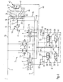
- a control device 1 for a hydraulic motor 2 is shown, which is formed in the illustrated embodiment as a double motor.
- the hydraulic motor 2 is connected to a first main line 3 and a second main line 4.
- a pressure medium is conveyed by the hydraulic pump either in the first main line 3 or in the second main line 4, whereby the direction of rotation of the hydraulic motor 2 is determined.
- the hydraulic motor 2 designed as a double motor has a first partial motor 5 and a second partial motor 5 ', which drive a common output shaft 33.
- the hydraulic motor 2 is variable in its displacement, for which purpose both the first motor part 5 and the second motor part 5 'are adjustable.
- a control pressure acting in a first setting unit 8 is controlled via a setting pressure control device 6.
- the actuating unit 8 has an actuating piston 9, which is arranged in an actuating cylinder 10 and divides the actuating cylinder 10 into a first pressure chamber 11 and a second pressure chamber 12.
- the control piston 9 changes its position and thus adjusts the displacement of the first sub-engine 5.
- a second adjusting unit 8' is provided, which is identical in construction to the first adjusting unit 8 and together with this an adjusting device 7 for the hydraulic motor 2 is formed.
- the corresponding elements of the second actuator 8 ' are the same, but apostrophized reference numerals provided in the explanation of the first actuator 8.
- the pressure medium that is required for adjusting the first adjusting unit 8 is removed via a pressure medium flushing device 13 from the first main line 3 or from the second main line 4.
- the first main line 3 and the second main line 4 are connected to a purge valve 14, which in each case those first or second main line 3 or 4, in which the lower pressure prevails via a throttle 15 and a pressure relief valve 16 with a tank volume 17 connects.
- the second pressure chamber 12 is connected directly to the pressure medium flushing device 13 via a pressure medium feed line 18.
- the pressure medium supply line 18 removes the pressure medium required for the first control unit 8 upstream of the throttle 15. Upstream of the throttle 15 there is an approximately constant pressure level, which is adjusted by the pressure relief valve 16.
- the pressure relief valve 16 opens when the downstream of the throttle 15 is adjusting pressure exceeds the force of a force acting on the pressure relief valve 16 spring.
- the purge valve 14 is a 3/3-way valve, which is acted upon by a first centering spring 19 and a second centering spring 20 with a restoring force in the direction of its central position. Furthermore, the flushing valve 14 has a first measuring surface 21 and a second measuring surface 22, which are each acted upon by the pressure of the first main line 3 via a first connecting line 3a and with the pressure of the second main line 4 via a second connecting line 4a. When a pressure difference occurs between the first main line 3 and the second main line 4, the purge valve 14 is off deflected out of its center position in a first or a second switching position.
- the delivery pressure prevailing in the first main conduit 3 exceeds the pressure in the second main conduit 4
- a greater hydraulic force acts on the first measurement surface 21 than on the second measurement surface 22 and the purge valve 14 connects the second connection 24 with the output port 25 So promoted by the hydraulic pump, not shown in the first main line 3 pressure medium under pressure, as z. B. in an accelerated ride or a ride in the plane is the case
- a portion of the conveyed pressure medium via the pressure medium flushing device 13 into the tank volume 17 is passed from the downstream of the hydraulic motor 2 located second main line 4.
- the pressure medium taken in the example of the second main line 4 is stowed at the throttle 15, wherein upstream of the throttle 15, an approximately constant pressure is achieved by the pressure relief valve 16.
- the signal pressure regulating device 6 has a pressure regulating valve 26.
- the pressure regulating valve 26 By means of the pressure regulating valve 26 is the first pressure chamber 11 connected in a first end position with the tank volume 17 and in a second end position with the pressure medium supply line 18. The adjustment of the pressure regulating valve 26 takes place continuously between the two end positions. Via a compression spring 27, the pressure regulating valve 26 is held in its first end position, in which the first pressure chamber 11 is connected via a control pressure line 29 to the tank volume 17.
- a proportional solenoid 28 For controlling the position of the pressure regulating valve 26 counteracts the force of the compression spring 27 is a proportional solenoid 28 which is acted upon via a non-illustrated electronic control unit with a controlled variable.
- the control pressure in the first pressure chamber 11 must be increased.
- the proportional solenoid, 28 is de-energized, the pressure control valve 26 is in its initial position, which is determined by the force of the compression spring 27.
- the first pressure chamber 11 is then connected to the tank volume 17 and the actuating piston 9 is brought by the acting in the second pressure chamber 12 on the actuating piston 9 force in its right in FIG. 1 end position in which the first engine part 5 has a maximum displacement ,
- the pressure control valve 26 By energizing the proportional magnet 28, the pressure control valve 26 is deflected in the direction of its second end position, so that the control pressure line 29 is increasingly connected in dependence on the force acting on the proportional solenoid 28 controlled variable with the pressure medium supply line 18.
- the maximum pressure that can be set in the first pressure chamber 11 is the same as the pressure prevailing in the second pressure chamber 12. Due to the larger in the first pressure chamber 11 with actuating pressure surface of the actuating piston 9 acts on the actuating piston 9, a resultant force, which adjusts the first engine part 5 in the direction of a smaller displacement.
- Corresponding components are in turn provided with the same, used in the description of the adjustment of the first part of the motor 5, but apostrophized reference numerals.
- the use of the control device shown in the embodiment has the advantage, especially for the use of double motors as a hydraulic motor 2, that a loss of efficiency is avoided by removing the pressure medium required for the adjustment on the low pressure side. In addition, it should be taken into account in particular when using double motors that a doubling of the number of sealing points occurs. Therefore, the use of the low pressure for adjusting a significant potential for saving the costly high-pressure seals available.
- FIG. 2 shows a second example of a control device 1 'according to the invention.
- FIG. 2 Those elements that are identical to those of the first embodiment, are provided in FIG. 2 with identical reference numerals. In order to avoid unnecessary repetition, a re-description of identical elements is omitted, unless it is necessary for understanding.
- the control device 1 'of the second embodiment comprises a control pressure regulating device 6', which regulates the control pressure in the first pressure chambers 11 and 11 'of the first control unit 8 and the second control unit 8'.
- the control pressure control device 6 ' is constructed symmetrically like the control pressure control device 6 of the first embodiment.
- the interacting with the second actuator 8 'components of the variable-pressure control valve 6' are again provided with apostroph convinced reference numerals, so that the description can be limited to the cooperating with the first actuator 8 of the first motor part 5 elements.
- a hydraulically actuated pressure control valve 35 which is held by means of an adjustable spring 36 in its initial position. In this initial position, the pressure medium supply line 18 via the control pressure line 29, with the first pressure chamber 11 is connected. If the adjusting piston 9 is adjusted by the pressure prevailing in the first pressure chamber 11 in such a way that the volume of the first pressure chamber 11 increases, the check valve 30 opening in the direction of the first pressure chamber 11 opens.
- a delivery pressure measuring surface 37 is formed on the pressure control valve 35, so that one on the delivery pressure measuring surface 37 attacking hydraulic force the pressure control valve 35 against the force of the adjustable spring 36 adjusted. If the system is put into operation after a rest phase, that is, no control intervention has yet been carried out, then the first partial motor 5 is in its basic position, in which it is pivoted to a minimum displacement, with the control piston 9 being left in FIG ,
- an override pressure measuring surface 38 is formed on the pressure control valve 35.
- the override pressure measuring surface 38 can be acted upon via an over-control valve 39 with the pressure of the pressure medium supply line 18.
- the over-control valve 39 is held in its rest position by means of a compression spring 40, in which the over-pressure measuring surface 38 is connected to the tank volume 17 and no pressure acts on the over-pressure measuring surface 38.
- a solenoid 41 By means of a solenoid 41, the over-control valve 39 is brought if necessary from the rest position against the force of the compression spring 40 in a switching position in which the pressure medium supply line 18 is connected to the override pressure measuring surface 38.
- the over-control valve 39 is in its rest position and the control pressure prevailing in the first pressure chamber 11 is determined by the equilibrium position of the pressure control valve 35 that is established.
- the equilibrium position of the pressure regulating valve 35 is determined by the force of the adjustable spring 36 and the acting in the opposite direction hydraulic force at the delivery pressure measuring surface 37.
- a high pressure-dependent control is shown.
- the pressure of the first main line 3 or the second main line 4 via a directional control valve 42 of the delivery pressure measuring surface 37 is supplied.
- Position of the directional control valve 42 in which the direction of travel valve 42 is held by a further compression spring 43, the second main line 4 is connected via a second main line section 4 b with a delivery pressure measuring line 44. This position assumes the direction of travel valve 42 when the second main line 4 is supplied with pressure medium by the hydraulic pump, not shown.
- the high pressure generated by the hydraulic pump is applied in the second main line 4.
- This high pressure also acts on the delivery pressure measuring surface 37 via the directional control valve 42 and the delivery pressure measuring line 44, so that the pressure regulating valve 35 assumes an equilibrium position which is determined by the force of the adjustable spring 36 and the opposing hydraulic force, which is dependent on that prevailing in the second main line 4 High pressure is determined.
- the force acting on the delivery pressure measuring surface 37 increases.
- the resulting adjusting movement of the pressure regulating valve 35 causes an increasing connection of the first pressure chamber 11 with the tank volume 17.
- the control pressure in the first pressure chamber 11 is thereby expanded via the throttle 32 into the tank volume 17, so that the force acting on the control piston 9 hydraulic force of the control pressure decreases and acting in the second pressure chamber 12 counterforce the control piston 9 in the direction of a larger absorption volume of first sub-motor 5 adjusted. If such an increase in the pressure in the second main line 4 results, for example, from an increase which the vehicle is driving up, the hydraulic motor 2 is adjusted in the direction of a larger absorption volume and thus at the same time in the direction of a greater torque with the described adjustment.
- the switching of the directional control valve 42 is due solely to the promotion of the hydraulic pump in the first main line 3 or the second main line 4. This has the consequence that at a pressure reversal in the main lines, as occurs for example in a delay or a descent, the pressure in the upstream of the hydraulic motor 2 located first or second main line 3,4 decreases and due to the decreasing hydraulic force at the delivery pressure measuring surface 37, the pressure control valve 35 is moved in the direction of its initial position.
- This adjustment causes an increasing connection of the first pressure chamber 11 with the pressure medium supply line 18. According to the increasing connection, the control pressure in the first pressure chamber 11 is increased and the first partial motor 5 is adjusted in the direction of a reduced absorption volume.
- the directional control valve 42 is actuated by an electronic control unit, not shown, and operates in dependence on the direction of travel.
- the over-control valve 39 can also be actuated when, with a slight delay, the pressure at the delivery pressure measuring surface 37 decreases and an adjustment of the first part-motor 5 in the direction of smaller pivoting angles is not desired.
- By actuation of the solenoid 41 then additionally acts the pressure of each of the downstream of the hydraulic motor 2 located first or second main line 3 or 4, unless the delay is sufficient to cause a pressure reversal in the first and second main line 3 and 4.
- the proposed control device 1, 1 ' can be used both in an open circuit and in a closed circuit, wherein advantageously can be used in particular in a closed circuit that a removal of already heated pressure fluid from the circulation is required in any case to enter the circulation to be able to return cooled pressure medium.
Landscapes
- Engineering & Computer Science (AREA)
- General Engineering & Computer Science (AREA)
- Mechanical Engineering (AREA)
- Physics & Mathematics (AREA)
- Fluid Mechanics (AREA)
- Fluid-Pressure Circuits (AREA)
- Hydraulic Motors (AREA)
Applications Claiming Priority (2)
| Application Number | Priority Date | Filing Date | Title |
|---|---|---|---|
| DE2002159315 DE10259315C5 (de) | 2002-12-18 | 2002-12-18 | Regelvorrichtung für einen Hydromotor |
| EP03027327A EP1431627A1 (fr) | 2002-12-18 | 2003-11-26 | Dispositif de commande pour un moteur hydraulique |
Related Parent Applications (1)
| Application Number | Title | Priority Date | Filing Date |
|---|---|---|---|
| EP03027327A Division EP1431627A1 (fr) | 2002-12-18 | 2003-11-26 | Dispositif de commande pour un moteur hydraulique |
Publications (2)
| Publication Number | Publication Date |
|---|---|
| EP1918616A2 true EP1918616A2 (fr) | 2008-05-07 |
| EP1918616A3 EP1918616A3 (fr) | 2008-08-13 |
Family
ID=32336450
Family Applications (2)
| Application Number | Title | Priority Date | Filing Date |
|---|---|---|---|
| EP07023161A Withdrawn EP1918616A3 (fr) | 2002-12-18 | 2003-11-26 | Dispositif de réglage pour un moteur hydraulique |
| EP03027327A Withdrawn EP1431627A1 (fr) | 2002-12-18 | 2003-11-26 | Dispositif de commande pour un moteur hydraulique |
Family Applications After (1)
| Application Number | Title | Priority Date | Filing Date |
|---|---|---|---|
| EP03027327A Withdrawn EP1431627A1 (fr) | 2002-12-18 | 2003-11-26 | Dispositif de commande pour un moteur hydraulique |
Country Status (2)
| Country | Link |
|---|---|
| EP (2) | EP1918616A3 (fr) |
| DE (1) | DE10259315C5 (fr) |
Cited By (1)
| Publication number | Priority date | Publication date | Assignee | Title |
|---|---|---|---|---|
| DE102014208916A1 (de) * | 2014-05-12 | 2015-11-12 | Zf Friedrichshafen Ag | Anordnung zum Ansteuern einer Hydraulikmaschine |
Families Citing this family (4)
| Publication number | Priority date | Publication date | Assignee | Title |
|---|---|---|---|---|
| EP1894765B1 (fr) * | 2006-08-30 | 2011-07-20 | Kobelco Cranes Co., Ltd. | Commande d'un système de traction hydrostatique |
| FR2953897B1 (fr) * | 2009-12-14 | 2012-01-20 | Poclain Hydraulics Ind | Gavage supplementaire pour circuit de transmission hydrostatique |
| DE102010006464B4 (de) | 2010-02-01 | 2021-02-18 | Robert Bosch Gmbh | Hydraulikanordnung |
| DE102016011778A1 (de) * | 2016-08-11 | 2018-02-15 | M A E Maschinen- Und Apparatebau Götzen Gmbh | Hydraulische, insbesondere druckspeicherlose, Antriebsanordnung für und mit einem Verbraucher, insbesondere für Pressen, sowie Verfahren zum Betreiben einer solchen hydraulischen Antriebsanordnung |
Citations (1)
| Publication number | Priority date | Publication date | Assignee | Title |
|---|---|---|---|---|
| EP0615588B1 (fr) | 1992-10-15 | 1995-08-23 | Brueninghaus Hydromatik Gmbh | Transmission hydrostatique |
Family Cites Families (9)
| Publication number | Priority date | Publication date | Assignee | Title |
|---|---|---|---|---|
| DE2409684A1 (de) * | 1974-02-28 | 1975-09-04 | Hydromatik Gmbh | Stellanordnung fuer ein hydrostatisches getriebe |
| DE3729495A1 (de) * | 1987-09-03 | 1989-03-16 | Brueninghaus Hydraulik Gmbh | Sekundaergeregeltes hydrostatisches getriebe mit offenem kreislauf |
| JP2818474B2 (ja) * | 1990-07-04 | 1998-10-30 | 日立建機株式会社 | 油圧駆動回路 |
| DE4029548A1 (de) * | 1990-09-18 | 1992-03-19 | Hydromatik Gmbh | Steuer- und regelvorrichtung fuer ein hydrostatisches getriebe |
| DE4329689C1 (de) * | 1993-09-02 | 1995-02-23 | Hydromatik Gmbh | Steuervorrichtung für ein hydrostatisches Getriebe |
| JP3400178B2 (ja) * | 1995-03-31 | 2003-04-28 | 日立建機株式会社 | 油圧駆動車両の走行制御装置 |
| JPH11166623A (ja) * | 1997-12-08 | 1999-06-22 | Komatsu Ltd | 複数の油圧モータとクラッチの制御装置および制御方法 |
| DE19850162C1 (de) * | 1998-10-30 | 2000-09-07 | Brueninghaus Hydromatik Gmbh | Hydrostatisches Getriebe |
| DE10138519A1 (de) * | 2001-08-06 | 2003-03-06 | Brueninghaus Hydromatik Gmbh | Hydromotor mit Bremseinrichtung |
-
2002
- 2002-12-18 DE DE2002159315 patent/DE10259315C5/de not_active Expired - Fee Related
-
2003
- 2003-11-26 EP EP07023161A patent/EP1918616A3/fr not_active Withdrawn
- 2003-11-26 EP EP03027327A patent/EP1431627A1/fr not_active Withdrawn
Patent Citations (1)
| Publication number | Priority date | Publication date | Assignee | Title |
|---|---|---|---|---|
| EP0615588B1 (fr) | 1992-10-15 | 1995-08-23 | Brueninghaus Hydromatik Gmbh | Transmission hydrostatique |
Cited By (1)
| Publication number | Priority date | Publication date | Assignee | Title |
|---|---|---|---|---|
| DE102014208916A1 (de) * | 2014-05-12 | 2015-11-12 | Zf Friedrichshafen Ag | Anordnung zum Ansteuern einer Hydraulikmaschine |
Also Published As
| Publication number | Publication date |
|---|---|
| EP1431627A1 (fr) | 2004-06-23 |
| DE10259315B3 (de) | 2004-10-07 |
| EP1918616A3 (fr) | 2008-08-13 |
| DE10259315C5 (de) | 2009-07-02 |
Similar Documents
| Publication | Publication Date | Title |
|---|---|---|
| DE3022918A1 (de) | Druck-uebersteuer-steuervorrichtung | |
| EP0144788B1 (fr) | Dispositif de régulation de puissance d'une transmission hydraulique à débit variable | |
| DE3118576A1 (de) | Regeleinrichtung fuer eine verstellpumpe | |
| DE2704326A1 (de) | Druckmittelstroemungssteuerung | |
| EP1828642B1 (fr) | Dispositif d'entrainement hydrostatique a limitation de la vitesse de rotation | |
| EP0935713A1 (fr) | Systeme de soupape et procede de realisation | |
| EP0530842B1 (fr) | Transmission réversible hydrostatique avec soupape de freinage | |
| DE69005591T2 (de) | Hydraulische Retarder mit Steuerung. | |
| DE2231421A1 (de) | Hydrostatisches getriebe | |
| WO2000073667A1 (fr) | Commande hydraulique comportant plusieurs consommateurs hydrauliques comprenant egalement un verin differentiel | |
| DE3734903C2 (de) | Blockiergeschützte hydraulische Kraftfahrzeugbremsanlage | |
| CH628117A5 (en) | Brake-valve device | |
| EP0615589B1 (fr) | Dispositif de commande d'une transmission hydrostatique avec soupape de frein | |
| EP0043459B1 (fr) | Dispositif de réglage pour un ensemble de plusieurs pompes entraînées par une source d'énergie commune | |
| EP1918616A2 (fr) | Dispositif de réglage pour un moteur hydraulique | |
| EP0715698B1 (fr) | Transmission hydrostatique pourvue d'une soupape de frein | |
| DE69703170T2 (de) | Hydrauliksystem | |
| DE2352622A1 (de) | Hydraulisches steuersystem fuer ein automatisches getriebe | |
| WO2008064850A1 (fr) | Entraînement hydrostatique comportant un dispositif de régulation à sommation de puissance | |
| DE1961930A1 (de) | Hydraulische Drehantriebsvorrichtung | |
| DE2218472A1 (de) | Hydrostatisches getriebe | |
| DE19642567C1 (de) | Kombiniertes Hydraulikventil mit einer Schalt- und einer Druckminderfunktion | |
| DE4226893C2 (de) | Hydraulische Drucksteuerung für einen Verbraucher sowie Verfahren zur Ansteuerung eines hydraulischen Verbrauchers unter Verwendung einer solchen Drucksteuerung | |
| EP0133475B1 (fr) | Dispositif de commande hydraulique | |
| DE2126230B2 (de) | Hydrostatisches Getriebe |
Legal Events
| Date | Code | Title | Description |
|---|---|---|---|
| PUAI | Public reference made under article 153(3) epc to a published international application that has entered the european phase |
Free format text: ORIGINAL CODE: 0009012 |
|
| 17P | Request for examination filed |
Effective date: 20071129 |
|
| AC | Divisional application: reference to earlier application |
Ref document number: 1431627 Country of ref document: EP Kind code of ref document: P |
|
| AK | Designated contracting states |
Kind code of ref document: A2 Designated state(s): DE FR GB IT SE |
|
| PUAL | Search report despatched |
Free format text: ORIGINAL CODE: 0009013 |
|
| AK | Designated contracting states |
Kind code of ref document: A3 Designated state(s): DE FR GB IT SE |
|
| AKX | Designation fees paid |
Designated state(s): DE FR GB IT SE |
|
| STAA | Information on the status of an ep patent application or granted ep patent |
Free format text: STATUS: THE APPLICATION IS DEEMED TO BE WITHDRAWN |
|
| 18D | Application deemed to be withdrawn |
Effective date: 20090214 |