EP1918853A2 - Détection et adaptation de marqueur de voie et adaptation - Google Patents
Détection et adaptation de marqueur de voie et adaptation Download PDFInfo
- Publication number
- EP1918853A2 EP1918853A2 EP07119254A EP07119254A EP1918853A2 EP 1918853 A2 EP1918853 A2 EP 1918853A2 EP 07119254 A EP07119254 A EP 07119254A EP 07119254 A EP07119254 A EP 07119254A EP 1918853 A2 EP1918853 A2 EP 1918853A2
- Authority
- EP
- European Patent Office
- Prior art keywords
- lane marker
- peak
- line
- width
- left edge
- Prior art date
- Legal status (The legal status is an assumption and is not a legal conclusion. Google has not performed a legal analysis and makes no representation as to the accuracy of the status listed.)
- Granted
Links
Images


Classifications
-
- G—PHYSICS
- G06—COMPUTING OR CALCULATING; COUNTING
- G06V—IMAGE OR VIDEO RECOGNITION OR UNDERSTANDING
- G06V20/00—Scenes; Scene-specific elements
- G06V20/50—Context or environment of the image
- G06V20/56—Context or environment of the image exterior to a vehicle by using sensors mounted on the vehicle
- G06V20/588—Recognition of the road, e.g. of lane markings; Recognition of the vehicle driving pattern in relation to the road
-
- G—PHYSICS
- G06—COMPUTING OR CALCULATING; COUNTING
- G06V—IMAGE OR VIDEO RECOGNITION OR UNDERSTANDING
- G06V10/00—Arrangements for image or video recognition or understanding
- G06V10/40—Extraction of image or video features
- G06V10/44—Local feature extraction by analysis of parts of the pattern, e.g. by detecting edges, contours, loops, corners, strokes or intersections; Connectivity analysis, e.g. of connected components
- G06V10/443—Local feature extraction by analysis of parts of the pattern, e.g. by detecting edges, contours, loops, corners, strokes or intersections; Connectivity analysis, e.g. of connected components by matching or filtering
Definitions
- the invention relates generally to lane tracking for vehicle safety and other applications, and more particularly to lane marker detection and fitting a straight or curved lane marker to a collection of potential lane marker objects in a camera image.
- Vision based lane tracking systems have been designed that are supposed to monitor a vehicle position by imaging a roadway and detecting lane markers. These lane tracking systems can be used for lane departure warning, or in more advanced systems may even be used for lane keeping assistance or automated vehicle guidance systems.
- a camera captures images of a roadway in front of a vehicle and imaging processing software identifies the lane markers from the roadway.
- the vision system can then determine the vehicle position relative to the lane markers, for displaying vehicle positioning information to a driver, warning a driver of an unintended lane departure, detecting driving patterns such as those indicative of a drowsy driver, or use in a collision warning/avoidance system.
- Conventional image processing systems are advancing in capabilities and provide an opportunity for improving vehicle occupant safety and vehicle guidance.
- the present invention provides a method of detecting and modeling a lane marker.
- a lane marker is modeled in one dimension as a bright marker on a relatively darker road, having an unknown width in the range of a minimum marker width to a maximum marker width.
- a lane marker model is split into a left step and a right step, wherein the right step is a negative value of a value of the left step.
- a cumulative row sum is calculated from the lane marker model.
- a matched filter response is calculated from the cumulative row sum, and the matched filter response is normalized by compensating for filter size by dividing the matched filter response by a sum of an absolute value of a matched filter coefficient.
- the matched filter response is also normalized by compensating for illumination by normalizing for illumination of apparent brightness of the lane marker and brightness of a road on which the lane marker is located.
- Normalizing for apparent brightness of the lane marker is achieved by dividing the normalized matched filter response by a bright section measurement of the matched filter response to obtain an illumination normalized response. Normalizing for the brightness of the road is achieved by defining an "inside neighborhood,” as described infra.
- a lane marker matched filter response is peak detected for both positive and negative peaks.
- a lane marker response has a magnitude above a threshold and is a local peak in a five point neighborhood centered about a point, as described infra.
- Thresholding is based on measurements from collected road images and is based on two tests.
- a normalized difference between a left and a right side has a magnitude above a threshold that is a function of estimated illumination, and the average brightness of the brighter side, presumed to be a lane marker, is brighter than an inside neighborhood brightness (road without a lane marker).
- the present also provides efficient algorithms to match "best" left and right edge detections of a potential marker detection.
- a minimum lane marker width and a maximum lane marker width are also transformed to a width in pixels for each row of an image.
- the present invention also provides a method of fitting a lane marker to a collection of one-dimensional detection of potential lane marker objects, for lane tracking.
- a Hough transform is utilized to determine a line fit of the lane marker.
- the Hough transform is extended to multiple planes to use lane marker features to determine a "best line” or curve.
- a "best line” means that a true lane marker is better than a grind mark, paving seam, tar patch, skid mark, etc.
- the lane marker features include a mean and variance of at least one of lane marker brightness, lane marker width, lane marker parallelism to a host vehicle direction of travel, and consistence with a predicted lane marker characteristic.
- the extension of the Hough transform to multiple planes is performed prior to a selection of a best line, wherein accumulated values in a Hough plane bin are modified to account for a preferred lane marker feature.
- the accumulated values in the Hough plane bin are modified by generating a value in a plurality of auxiliary planes' bins to the Hough plane bin (wherein the generated value represents a characteristic of the lane marker), assigning a penalty factor to the auxiliary plane bin reflecting an extent to which the auxiliary plane bin value varies from the preferred lane marker feature, and multiplying the penalty factor to the Hough plane bin to generate a modified Hough plane bin.
- a closest lane marker line to the host vehicle is identified from a plurality of lane marker lines situated adjacent to the host vehicle.
- Substantially parallel lane marker lines are identified from the plurality of lane marker lines, measured from a maximum predetermined lane marker distance from the host vehicle to the host vehicle.
- a threshold peak is identified within a five-point neighborhood (described infra), situated closest to the host vehicle, from the substantially parallel lane marker lines.
- the present invention further determines a refitted lane marker line.
- the points corresponding to the Hough transform lane marker line are also refitted with a weighted least squares fit.
- a method and system is described herein for providing lane marker detection and modeling, and fitting a straight or curved lane marker to a collection of potential lane marker objects in a camera image, for vehicle occupant safety and other applications.
- the present invention takes into account complicating real world considerations including lighting conditions, low sun angles, shadows, skid marks, patching or paving seams, irregular lane markers, faded markers, lane marker curvature, etc.
- FIG. 1A and FIG. 1B illustrate a lane marker model and a split lane marker model, respectively.
- lane marker detection is modeled as a row-by-row, one-dimensional detection process.
- Other embodiments include modeling the lane marker detection consecutively or non-consecutively (processing only the even or odd numbered rows), modeling by column, and in two dimensions.
- the lane marker detection is modeled as a one-dimensional line at a rational slope having n rows/m columns. For each row, the lane marker is modeled as a bright bar on a relatively dark background having an unknown width W, in the range of a minimum marker width to a maximum marker width, since lane widths vary from place to place.
- the lane marker model is split into a left step and a right step, avoiding the need to compute matched filters for all possible marker widths.
- the matched filters for the left edge and the right edge are shown in FIG. 2A and FIG. 2B, respectively.
- the right step filter is a negative version of the left step filter, and thus in an embodiment, only the left step filter response is calculated.
- L min is defined as the minimum lane marker width
- L max is defined as the maximum lane marker width.
- L min is a function of the position in the image. It is the width in pixels of the minimum lane marker width in the world perspective transformed into the image plane. If the camera roll and pan angles are small, L min can be approximated as a function of the image row.
- a calculation based on computing the cumulative row sum s for the row and then the matched filter response can be determined at each index point along the row with adds and/or subtracts.
- Equation 1 Let p be the starting index column of the region of interest for row m .
- the image pixel in row m , column k is x mk .
- the matched filter response is normalized to compensate for the effective pixel scale size of the filter and for the effects of illumination.
- To normalize for the effective pixel scale the result is divided by the sum of the absolute value of the matched filter coefficients (1 ⁇ 2 L min ). It is to be appreciated that the factor 2 of the matched filter coefficient can vary as long as the scale transforms produce the same relative value. As an example, FIG. 2A and 2B show 2L pixels, so it is normalized by 2L.
- the apparent brightness of the lane marker is approximated as a product of the illumination and the object reflectance.
- the filter output is proportional to the apparent brightness.
- the relative illumination based on the bright part of the filter response is estimated.
- f dark k min( f right k , f left k ,) is the dark filter response
- f bright k max( f right k , f left k ) is the bright filter response.
- the apparent brightness of the road (not including the marker portion) is also approximately determined.
- the width of the inside neighborhood is defined as about 0.4 meters to 0.8 meters from an edge of the lane marker toward the image center.
- the image center is frequently near the center of a lane, wherein a typical lane is about 3.5 meters wide. This definition takes into account that true lane markers are likely to be an approximate distance outside of the image center, and the region toward the image center is likely to be the road.
- W k is defined as an observed road brightness.
- L inside is a predetermined width from an outer edge of the lane marker toward an image center.
- L max is a filter pixel scale width of a maximum real world width of the lane marker.
- the lane marker response is also peak detected for both positive and negative peaks. Positive peaks correspond to left lane marker edge locations, and negative peaks correspond to right lane marker edge locations.
- the lane marker response must be above a threshold and must be a local peak in a five point neighborhood centered about a point. The five point neighborhood is defined in either Equations 10A or 10B.
- Thresholding is defined herein as an ad-hoc technique based on measurements from collected road images and based on two tests, shown in equation 9A.
- the first threshold test requires that a normalized difference between the left and right side have a magnitude above a threshold that is a function of estimated illumination.
- the second threshold test requires that the average brightness of the brighter side, presumed to be a marker, is brighter than the inside neighborhood brightness.
- the inside neighborhood is defined as road but not lane marker.
- An alternative form of the second threshold test is to compare to a threshold that is the mean divided by the inside threshold plus some predetermined constant times the standard deviation divided by the inside neighborhood.
- Equation 9A If Equation 9A is true (using the definitions 9B and 9C), then the response at k is considered above threshold.
- the thresholding functions shown in Definitions 9B and 9C were experimentally determined by measured roadway images collected with a CMOS camera taken through an automobile windshield. The following experimental result examples are provided for illustrative purposes and are not intended to be limiting. ⁇ 1 f bright k ⁇ min ⁇ 13 ⁇ 1 + 255 - f bright k 255 , 0.3 ⁇ f bright k ⁇ 1 w k ⁇ min 1.05 ⁇ w k , 250
- FIG. 3 illustrates a graphical representation of the first threshold test with applied Definition 9B.
- FIG. 4 illustrates a graphical representation of the second threshold test with applied Definition 9C.
- a peak is defined herein as being based on a five point neighborhood, as shown in Equations 10A and 10B.
- the fifth point is point Z k . If z k > 0 (for positive peaks) z k - 2 ⁇ z k and z k - 1 ⁇ z k and z k - 1 ⁇ z k and z k - 2 ⁇ z k Else (for negative peaks) z k - 2 > z k and z k - 1 ⁇ z k and z k - 1 ⁇ z k and z k - 2 > z k If the threshold condition and the local peak condition at pixel k are true (as described supra), then k is declared an edge location.
- a marklet as defined herein is a potential lane marker detection characterized by a left edge peak point followed by a matching right edge peak point, whose width is in the range of a minimum maker width to a maximum marker width. Marklets are represented herein by their center position, width, and pixel intensity at their center position. Lane markers are often imperfect and may be dirty, have smudged edges and are frequently painted misaligned on top of old lane markers.
- FIG. 5 An example of this is illustrated in FIG. 5 wherein a left edge is indicated by a plus sign and a right edge is indicated by a negative sign.
- the leftmost edge when paired with the right edge, presents a marker width that is greater than a predetermined maximum marker width.
- the remaining left edge, when paired with the right edge presents a marker width that is between a minimum marker width and a maximum marker width.
- the present invention detects the best set of marklets by considering all possible valid pair edge combinations and then pairs the best fitting edges. Edges are paired by preferring edges with the strongest edge strength. When scanning from left to right, for successive left edges without intervening right edges, the edge with the maximum illumination normalized response (the absolute value of Z k ) is selected. In another embodiment, when scanning from right to left, for successive right edges without intervening left edges, the edge with the maximum illumination normalized response is selected.
- Left and right edge peaks are combined into a set of marklets, by utilizing the following described methods.
- all combinations of a left edge followed by a right edge are considered, having a width within the allowed minimum maker width to the allowed maximum marker width.
- all combinations of a left edge followed by a right edge are considered, having a width within the allowed minimum maker width to the allowed maximum marker width, and then resolving which of the sets of pair-wise overlapped possible marklets is best with a combinatorial optimization technique.
- left and right edge peaks are paired by a greedy scan (greedy matching described infra) from left to right (or right to left) pairing the first encountered and valid non-overlapping marklets.
- a maximal left edge peak and a maximal right edge peak are paired (strongest edge matching described infra).
- the scanning first seeks a left edge peak. After a left edge peak is detected, the scanning seeks a right edge peak. The scanning distance extends from a minimum predetermined lane marker width distance to a maximum predetermined lane marker width distance, wherein the minimum predetermined lane marker width distance and the maximum predetermined lane marker width distance are measured from the left edge peak. Next, a marklet position is defined midway between the left edge peak and the right edge peak. If no matching right edge peak is detected, then the scanning seeks an alternate left edge peak from beyond the first left edge peak. An alternate right edge peak is then scanned from the minimum predetermined lane marker width distance to the maximum predetermined lane marker width distance, measured from the alternate left edge peak. An alternate marklet position is then defined midway between the alternate left edge peak and the alternate right edge peak. Also, the lane marker is modeled by at least one of row, column, one-dimension, two dimensions, consecutively, and non-consecutively.
- the scanning seeks a second left edge peak from beyond the previously matched first right edge peak. After a second left edge peak is detected, the scanning seeks a second right edge peak that matches the second left edge peak.
- the scanning distance extends from a minimum predetermined lane marker width distance to a maximum predetermined lane marker width distance, wherein the minimum predetermined lane marker width distance and the maximum predetermined lane marker width distance are measured from the second left edge peak.
- a second marklet position is defined midway between the second left edge peak and the second right edge peak. If no matching second right edge peak is detected, then the scanning seeks an alternative left edge peak from beyond the second left edge peak. Additionally, the scanning for the second left edge peak, the scanning for the second right edge peak, and the defining the second marklet position are iterative to define subsequent marklet positions.
- the scanning seeks a first left edge peak (called a current position), and then seeks successive left edge peaks until an intervening right edge peak is found.
- the left edge peak having a maximum illumination normalized response magnitude is identified from the left edge peaks.
- the scanning seeks at least one right edge peak.
- the scanning distance extends from a minimum predetermined lane marker width distance to a maximum predetermined lane marker width distance, wherein the minimum predetermined lane marker width distance and the maximum predetermined lane marker width distance are measured from the maximal left edge.
- a maximal right edge having a maximum illumination normalized response magnitude, is identified from the right edge peaks.
- a marklet position is then defined midway between the maximal left edge and the maximal right edge.
- the scanning seeks alternative left edge peaks from beyond the maximal left edge.
- the scanning seeks successive left edge peaks until an intervening right edge peak is found.
- the left edge peak having a maximum illumination normalized response magnitude is identified from the left edge peaks.
- the scanning then seeks at least one right edge peak, extending from a minimum predetermined lane marker width distance to a maximum predetermined lane marker width distance, measured from the alternative maximal left edge.
- the lane marker is modeled by at least one of row, column, one-dimension, two dimensions, consecutively, and non-consecutively.
- the scanning seeks the next second left edge peak beyond the matched right edge peak (the second left edge peak is now designated as the current position), and then seeks successive left edge peaks until an intervening right edge peak is found.
- the left edge peak having a maximum illumination normalized response magnitude (second maximal left edge) is identified from the left edge peaks.
- the scanning seeks at least one right edge peak.
- the scanning distance extends from a minimum predetermined lane marker width distance to a maximum predetermined lane marker width distance, measured from the second maximal left edge.
- a second maximal right edge having a maximum illumination normalized response magnitude, is identified from the right edge peaks.
- a second marklet position is then defined midway between the second maximal left edge and the second maximal right edge. Additionally, the scanning for the second left edge peak, the scanning for the second right edge peak, and the defining the second marklet position are iterative to define subsequent marklet positions.
- the scanning seeks lane markers from right to left, or along a straight line in the image with the line at a predetermined slope (i.e., 45 degree line and or - 45 degree line).
- a predetermined slope i.e. 45 degree line and or - 45 degree line.
- the minimum and the maximum lane marker widths are transformed to pixel width for each row of an image.
- pixel width typically 0.08 m to 0.42 m
- a “best” straight line or curve is fit to a collection of low level marklet point detections. "Best” as used herein means that a true lane marker is better than a grind mark, paving seam, tar patch, skid mark, and the like.
- a marklet has the properties of width, point (x i , y i ) of the center of the one-dimensional marklet, and average intensity over the width of the marklet. Marklets are detected by scan-row in the image and inverse-perspective transformed to world coordinates. A set of marklets typically includes clutter points.
- a straight line is fitted for lane tracking wherein a lane marker is positioned close to the vehicle and the camera/detection device. However, a curve may be fitted as well for close lane tracking.
- the Hough transform is conventionally used to find straight lines based on sample measurements.
- x i , and y i be the spatial coordinates of the i th point.
- s and b vary, they describe an infinite number of possible lines that pass through the point ( x i , y i ).
- FIG. 7 shows the line of Equation 23 plotted in the sb parameter space plane.
- the j th point also describes a line in the sb parameter space plane.
- the two lines in the sb parameter space intersect at the point ( s', b' ) .
- All points that fall on the line defined by the points ( x i , y i ) and ( x j , y j ) describe lines in the sb parameter space plane that intersect in the same point, ( s', b' ) .
- the measured points have measurement noise (errors)
- the lines in the parameters space do not intersect in a single point, but will pair-wise intersect within a small region illustrated by the circle in FIG. 8.
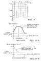
- FIG. 9 illustrates the quantized accumulator plane.
- a ( i, j ) is the accumulator associated with parameters ( s i , b j ) ; or more exactly, it is associated with all s and b values that fall within its rectangle of the parameter space.
- a (i,j) is the accumulator for all s such that S i + 1 + S i 2 ⁇ s ⁇ S i + S i + 1 2 and b such that b j + 1 + b j 2 ⁇ b ⁇ b j + b j + 1 2
- the slope, s is varied in quantized steps from s min to s max , and the resulting offset, b, is computed using Equation 23.
- b is then quantized into the closest bin between b min to b max based on Equation (24B).
- the value of the corresponding accumulator cell, A ( i,j ) is then incremented.
- accumulator cell A ( i, j ) with a value of a ij corresponds to a ij points lying on (near) a line with parameters s i and b j . Finding the lines then corresponds to finding all the cells of A with A ( i, j ) ⁇ a min .
- the lines that are near their predicted/estimated values are to be determined.
- the angle parameter space is quantized in terms of a fixed, uniform, angle quantization size.
- the offset parameter space size varies with the quality of the track. Searching for a lane marker looks over a larger offset space (typically ⁇ 2 m), while a steady-state track looks over a smaller offset space (typically ⁇ 0.5 m). It is desirable that a steady-state track have an offset space small enough that it will not get confused by clutter, but large enough so that it does not lose track from small vehicle pitching.
- the angle of the lane marker is usually small.
- An approximation of tan ⁇ or tan -1 ⁇ ⁇ ⁇ results in a worst case relative error of 2.3%, which is insignificant compared to the measurement noise.
- the nesting order of the loops: for each angle, for each point, can be interchanged to possibly improve memory access patterns. If the small angle approximation is used, and the tan/tan -1 are eliminated, then the programming code can be modified to iterate over offset instead of angle. If the number of quantized offset bins is less than the number of quantized angle bins, N ⁇ M , then iterating over offset reduces computation. However, if the "inside line” technique and the "memory minimization” technique (discussed infra) are used, the iteration must be over angle.
- the number of angle quantization bins, M, and the number offset quantization bins, N, are determined based on thee factors:
- the resulting parameter measurement errors are assumed to have independent Gaussian distributions and, since ⁇ ⁇ and b ⁇ result in a bin normalization based on variance, the parameter errors in the accumulator plane are Gaussian and circularly symmetric. Therefore, to mitigate the effect of bin splitting, the point mass is Gaussian blurred (convolved), rather than accumulating a point mass (weight) of one in the mapped accumulator bin.
- the Gaussian kernel is further approximated by a 3 by 3 weight matrix: 1 16 1 2 1 2 4 2 1 2 1 For performance reasons, the 1/16 weight term is dropped so that simple integer arithmetic can be used.
- Bin splitting blur kernel 1 2 1 2 4 2 1 2 1
- the blurring is implemented by convolving the kernel with the final accumulated values in A.
- the "impulse" measurement can be blurred by incrementing the neighbors by the kernel weighted values. The later is more efficient if the number of points is less than the number of accumulator bins, P ⁇ NM.
- the edge cases where the blur extends beyond the row/column limits of A present a unique situation.
- the simple expedient of not blurring on the first and last row and column of A is utilized.
- each marklet point measurement is assigned the same point mass, or weight. However, there are many potential reasons to weight each point differently, and assign “better” points and higher weights to find the "best line.”
- marklet points are situated on the ground plane of a camera perspective image. There are many more image rows per meter of the world for near marklet detections than for far marklet detections. For a solid line painted marker, in an embodiment, one marklet is detected per image row over the region of interest. Tilt only perspective transform from world (x, y) to image ( p, q ) coordinates:
- item 3 corresponds to weighting by inverse density (refer to equation 30).
- This weighting provides uniform weighting in world coordinates of marklets sampled in the perspective image coordinates.
- item 2 by linear distance results in the best line fits. Analytical models of the presumed measurement errors imply that the uniform weight is optimal. The experimental results with real world data obtain the best result with the linear distance weight.
- detection of the best "lane marker,” and not the best line is made and so characteristics of lane markers can be incorporated into the weightings.
- Lane markers are usually brighter than the road, tar patching, tire skid marks, etc. Thus, brighter marklets should be weighted heavier. However, this is not a completely valid assumption when shadows are present.
- Nominal width markers (about 12 cm) are more common than wide markers. Thus, nominal width marklets are weighted heavier.
- the variance of the width of the marklets belonging to a true marker should be low. Thus, low variance lines are weighted heavier.
- the present invention accommodates multiple weighting through a multi-plane extension of the Hough transform.
- preference for certain line characteristics is expressed. This method applies the notion that lines having these preferred characteristics are more likely to be real lane markers rather than false, clutter-related lines. For example, it is expected that a real lane marker results in detected marklets that have approximately the same width. A preference is expressed for lines that result from groups of marklets having a small variance in width. Similarly, there are fairly standard widths for lane markings, many of which have a width around 10-12 cm. Although much wider lane markings do occur, a preference is expressed for 'nominal' width lines by looking at the mean width of the marklets contributing to that line.
- Other preferences include a small residual (i.e., the candidate line is close in slope and offset to the tracker's prediction), a slope near zero (i.e., the line is nearly parallel to the host vehicle's direction of motion), and a high mean intensity (i.e., brighter lines are better).
- the quantities mentioned above can be calculated for a given line. However, the present invention further expresses all preferences prior to selection of a best line.
- the approach employed here modifies the accumulated values in the Hough plane bins.
- Each bin in this auxiliary plane contains a value representing that characteristic of the line corresponding to that bin (calculated from the marklets that contributed to that bin).
- a number between zero and one which is a multiplicative penalty reflecting the extent to which that particular preference is not satisfied, is subsequently calculated for each bin in the auxiliary plane. The greater the extent to which the preference is not satisfied, the closer the penalty factor is to zero.
- the way that the original Hough plane values are modified to account for the preferences is, for each bin, to multiply the original accumulated value cell-wise by all of the penalty factors from the corresponding bins in the auxiliary planes.
- there may be five auxiliary planes such as residual error, slope near zero, mean width, variance of width, and mean intensity.
- a particular bin in the Hough plane has an accumulated value of 300, and the corresponding bin in each of the 5 auxiliary planes generates penalty values 0.9, 0.95, 0.7, 0.85 and 0.9, respectively.
- data is also accumulated in the corresponding bins in the auxiliary planes, which allow a post-processing step to calculate the appropriate line characteristics (e.g., width variance) and subsequently the corresponding penalty values.
- line characteristics e.g., width variance
- the residual error and slope near zero terms do not require additional Hough planes, they are functions of the position (indices) in the parameters space and can be directly computed as part of the mass weight plane or in the post processing step of cell-wise combining the planes.
- the auxiliary planes are only needed to accommodate weighting terms that can not be determined until all the points have been mapped to bins.
- means and variance terms require separate planes because the mean and variance are not determined until all the points mapped to a bin are known.
- the mean and variance terms are implemented by computing four auxiliary planes: 1) the count of points mapped to the bin, 2) sum of intensity plane, 3) sum of width plane, and 4) square of width plane.
- the auxiliary planes are blurred in the same way that the main Hough plane is blurred.
- the present invention converts line characteristics (e.g., width variance) data stored in the auxiliary planes into penalties. For each characteristic, a plot is shown illustrating how the real-valued characteristic maps into a penalty value between zero and one. As illustrated in FIG. 10A, for the "mean width" characteristic, the penalty function is a Gaussian curve centered at the nominal marker width nominalWidth, and clipped to not return a penalty value smaller than minWidthPenaltyValue. The horizontal width of the Gaussian curve is adjusted using widthSigma. As illustrated in FIG.
- the penalty function decreases exponentially from a value of one at zero variance, and is clipped to not return a penalty value smaller than minVarPenaltyValue.
- the rate of descent of the exponential curve is adjustable.
- the exponential function of variance is meant to mimic (half of) a Gaussian curve in standard deviation.
- the "mean intensity” penalty function has a straight-line shape which passes through 1 at the maximum intensity of 255, and is controlled by a single parameter which determines the penalty where the intensity is zero.
- the "residual error" penalty function is the product of two penalty functions: (1) the slope residual penalty function; and (2) the offset residual penalty function.
- Each of these two penalty functions has a piecewise-linear shape which passes through 1 at zero residual, and drops to a specified minimum value (e.g., minOffsetResPenalty) at a specified residual value (e.g., offsetDiffForMaxPenalty).
- minOffsetResPenalty a specified minimum value
- offsetDiffForMaxPenalty a specified residual value
- the inside lane marker (the marker closest to the host vehicle) is located. It is to be appreciated that multiple lane markers of two through five parallel markers are used on roadways. To find the inside lane marker in the case of multiple markers, the multiple markers are taken as parallel (having the same angle). A search is conducted from the global maximum in the parameter space along the line of decreasing offset towards the host vehicle, with the slope/heading angle of the global best lane marker constant, looking for local peaks. Local peaks, as discussed supra, are defined by a five-point neighborhood centered about the current point. Experimental results show that, in some cases, a three-point neighborhood tends to generate false local peaks.
- FIG. 11 shows a line plot of Hough parameter space response with angle equal to the angle of the global maximum. Circles 1, 2 and 3 are peak in the Hough plane, circle 4 is the peak corresponding to the inside marker.
- the present invention significantly reduces the memory requirements of the Hough parameter space plane.
- the parameter space planes can be reduced in size from M by N to the size 4 by N, assuming a three by three blurring kernel.
- One row is used to hold the current best row, and three rows are used with circular addressing to hold the current row, the previous row, and the next row.
- the quality of the line fit increases as: the number of points on the line increases; the clutter ratio of points on the line to points not on the line increases; the range extent of points on the line increases; and variance of the marklet width of points on the line decreases.
- the definition herein of "quality measure of the resulting line” construes “on the line” to also mean “near the line” to accommodate measurement errors and quantization of the Hough parameter space.
- the present invention improves on the Hough transform to provide a mechanism to manage range dependent measurement errors in the marklet detections.
- a source of error for a straight line fit for marklet detections, which belong to true lane markers, are horizontal and vertical curvature.
- the straight line and flat world is less susceptible to gross modeling errors than higher order models and performs satisfactorily for lane departure warning.
- a lane marker may actually be curved, not a straight line, and the ground might not be flat. If the lane marker has a non-zero constant curvature, the measurement errors increase as the square of the range. However, most of the time the lane marker is a straight line, the world is flat (meaning having a constant inclination), and the relative measurement error is roughly constant.
- the present invention determines a geometric mean of a range independent measurement variance and a range squared measurement variance, and employs a linear or range weighted variance.
- the score of the line fit is the number of points on the line.
- the clutter ratio of the line fit is the score divided by the number of points.
- Another measure of clutter ratio is the score divided by (number of points minus number of points on parallel multiple lane markers).
- the support is the range extent (max ⁇ x i ⁇ - min ⁇ x i ⁇ ) of points, i , on the line.
- the width standard deviation is the unbiased standard deviation of the marklet widths of points on the line.
- the biased estimator may also be used for raised pavement marker detection mode.
Landscapes
- Engineering & Computer Science (AREA)
- Physics & Mathematics (AREA)
- General Physics & Mathematics (AREA)
- Multimedia (AREA)
- Theoretical Computer Science (AREA)
- Computer Vision & Pattern Recognition (AREA)
- Image Analysis (AREA)
- Image Processing (AREA)
- Traffic Control Systems (AREA)
Priority Applications (1)
| Application Number | Priority Date | Filing Date | Title |
|---|---|---|---|
| EP11151598A EP2328114B1 (fr) | 2006-11-03 | 2007-10-25 | Détection et adaptation de marqueur de voie et adaptation |
Applications Claiming Priority (1)
| Application Number | Priority Date | Filing Date | Title |
|---|---|---|---|
| US11/592,824 US7876926B2 (en) | 2006-11-03 | 2006-11-03 | Lane marker detection and fitting methods |
Related Child Applications (2)
| Application Number | Title | Priority Date | Filing Date |
|---|---|---|---|
| EP11151598A Division EP2328114B1 (fr) | 2006-11-03 | 2007-10-25 | Détection et adaptation de marqueur de voie et adaptation |
| EP11151598.7 Division-Into | 2011-01-20 |
Publications (3)
| Publication Number | Publication Date |
|---|---|
| EP1918853A2 true EP1918853A2 (fr) | 2008-05-07 |
| EP1918853A3 EP1918853A3 (fr) | 2009-07-15 |
| EP1918853B1 EP1918853B1 (fr) | 2011-06-22 |
Family
ID=38988130
Family Applications (2)
| Application Number | Title | Priority Date | Filing Date |
|---|---|---|---|
| EP11151598A Active EP2328114B1 (fr) | 2006-11-03 | 2007-10-25 | Détection et adaptation de marqueur de voie et adaptation |
| EP07119254A Active EP1918853B1 (fr) | 2006-11-03 | 2007-10-25 | Détection et adaptation de marqueur de voie et adaptation |
Family Applications Before (1)
| Application Number | Title | Priority Date | Filing Date |
|---|---|---|---|
| EP11151598A Active EP2328114B1 (fr) | 2006-11-03 | 2007-10-25 | Détection et adaptation de marqueur de voie et adaptation |
Country Status (3)
| Country | Link |
|---|---|
| US (1) | US7876926B2 (fr) |
| EP (2) | EP2328114B1 (fr) |
| AT (1) | ATE514140T1 (fr) |
Cited By (9)
| Publication number | Priority date | Publication date | Assignee | Title |
|---|---|---|---|---|
| EP2927869A3 (fr) * | 2014-04-04 | 2015-10-21 | Fujitsu Limited | Dispositif, procédé et programme d'estimation de mouvement |
| EP2725520A3 (fr) * | 2012-06-13 | 2016-07-13 | Ricoh Company, Ltd. | Procédé et appareil permettant de détecter la partition de route |
| WO2018128667A1 (fr) * | 2017-01-04 | 2018-07-12 | Qualcomm Incorporated | Systèmes et procédés de détection de marqueur de voie |
| CN110426681A (zh) * | 2019-07-31 | 2019-11-08 | 长春理工大学 | 一种基于同步提取s变换的lfm信号参数估计方法 |
| EP3567518A1 (fr) * | 2018-05-08 | 2019-11-13 | Aptiv Technologies Limited | Reconnaissance de marquage de voie |
| GB2589902A (en) * | 2019-12-12 | 2021-06-16 | Continental Automotive Romania Srl | Lane detection method |
| CN114639079A (zh) * | 2020-12-15 | 2022-06-17 | 北京百度网讯科技有限公司 | 匹配车道线数据的方法、装置、设备和存储介质 |
| CN117520814A (zh) * | 2023-10-31 | 2024-02-06 | 哈尔滨工业大学 | 一种共焦层析扫描的快速高斯拟合提取峰值的方法 |
| US12049172B2 (en) | 2021-10-19 | 2024-07-30 | Stoneridge, Inc. | Camera mirror system display for commercial vehicles including system for identifying road markings |
Families Citing this family (32)
| Publication number | Priority date | Publication date | Assignee | Title |
|---|---|---|---|---|
| US8249387B2 (en) * | 2008-03-31 | 2012-08-21 | Sungkyunkwan University Foundation For Corporate Collaboration | Image processing method and apparatus for detecting lines of images and start and end points of lines |
| US8699754B2 (en) * | 2008-04-24 | 2014-04-15 | GM Global Technology Operations LLC | Clear path detection through road modeling |
| US8311283B2 (en) * | 2008-07-06 | 2012-11-13 | Automotive Research&Testing Center | Method for detecting lane departure and apparatus thereof |
| US8204277B2 (en) * | 2008-07-18 | 2012-06-19 | GM Global Technology Operations LLC | Apparatus and method for camera-bases lane marker detection |
| US8194927B2 (en) * | 2008-07-18 | 2012-06-05 | GM Global Technology Operations LLC | Road-lane marker detection using light-based sensing technology |
| US8099213B2 (en) * | 2008-07-18 | 2012-01-17 | GM Global Technology Operations LLC | Road-edge detection |
| JP4710981B2 (ja) * | 2009-01-23 | 2011-06-29 | トヨタ自動車株式会社 | 区画線認識装置、及び当該装置で用いられる区画線認識方法 |
| JP4988786B2 (ja) * | 2009-04-09 | 2012-08-01 | 株式会社日本自動車部品総合研究所 | 境界線認識装置 |
| WO2011106578A2 (fr) | 2010-02-26 | 2011-09-01 | Gentex Corporation | Système automatique de surveillance, d'alerte et de commande d'équipement de véhicule |
| US9769430B1 (en) | 2011-06-23 | 2017-09-19 | Gentex Corporation | Imager system with median filter and method thereof |
| EP2549408A1 (fr) * | 2011-07-20 | 2013-01-23 | Delphi Technologies, Inc. | Procédé de détection et de classification d'objets |
| US9098751B2 (en) | 2011-07-27 | 2015-08-04 | Gentex Corporation | System and method for periodic lane marker identification and tracking |
| TWI434239B (zh) * | 2011-08-26 | 2014-04-11 | Ind Tech Res Inst | 後方來車變換車道預警方法及其系統 |
| EP2815393B1 (fr) | 2012-02-14 | 2023-04-05 | Gentex Corporation | Système d'imageur à haute gamme dynamique |
| DE102012215322A1 (de) * | 2012-08-29 | 2014-03-06 | Robert Bosch Gmbh | Verfahren und Vorrichtung zum Erkennen einer Position eines Fahrzeugs auf einer Fahrspur |
| DE102013217860A1 (de) * | 2013-09-06 | 2015-03-12 | Robert Bosch Gmbh | Verfahren und Vorrichtung zum Bestimmen eines Fahrbahnverlaufs einer Fahrbahn eines Fahrzeugs |
| US9483700B1 (en) | 2015-05-13 | 2016-11-01 | Honda Motor Co., Ltd. | System and method for lane vehicle localization with lane marking detection and likelihood scoring |
| KR102355321B1 (ko) * | 2015-09-10 | 2022-01-25 | 주식회사 만도모빌리티솔루션즈 | 차선 유지 보조 시스템 및 차선 유지 보조 방법 |
| EP3570262A4 (fr) * | 2017-01-10 | 2019-12-18 | Mitsubishi Electric Corporation | Dispositif de reconnaissance de trajet de déplacement et procédé de reconnaissance de trajet de déplacement |
| US10816354B2 (en) | 2017-08-22 | 2020-10-27 | Tusimple, Inc. | Verification module system and method for motion-based lane detection with multiple sensors |
| US11009356B2 (en) | 2018-02-14 | 2021-05-18 | Tusimple, Inc. | Lane marking localization and fusion |
| US11009365B2 (en) | 2018-02-14 | 2021-05-18 | Tusimple, Inc. | Lane marking localization |
| US12270661B2 (en) | 2018-02-14 | 2025-04-08 | Tusimple, Inc. | Lane marking localization and fusion |
| US11138447B2 (en) * | 2018-06-01 | 2021-10-05 | Connaught Electronics Ltd. | Method for detecting raised pavement markers, computer program product and camera system for a vehicle |
| CN109671095B (zh) * | 2018-12-19 | 2023-04-25 | 吉林大学 | 一种x光照片中金属物分离方法和相关装置 |
| CN112784633B (zh) * | 2019-11-07 | 2024-04-19 | 北京四维图新科技股份有限公司 | 一种车道边界的处理方法、装置、电子设备和存储介质 |
| CN111340833B (zh) * | 2020-02-20 | 2023-05-09 | 西安汇智信息科技有限公司 | 最小二乘去干扰随机Hough变换的输电线提取方法 |
| EP3893150A1 (fr) | 2020-04-09 | 2021-10-13 | Tusimple, Inc. | Techniques d'estimation de pose de caméra |
| CN111709964B (zh) * | 2020-06-22 | 2023-04-25 | 重庆理工大学 | 一种pcba目标边缘检测方法 |
| JP7616855B2 (ja) * | 2020-10-02 | 2025-01-17 | 株式会社Subaru | 車両の車線区画線認識装置 |
| US11636693B2 (en) * | 2021-01-20 | 2023-04-25 | Qualcomm Incorporated | Robust lane-boundary association for road map generation |
| CN118882695B (zh) * | 2024-07-10 | 2025-04-04 | 江西科技学院 | 基于DTW与Hough变换的轨检数据里程偏差确定方法 |
Citations (4)
| Publication number | Priority date | Publication date | Assignee | Title |
|---|---|---|---|---|
| EP0341985A2 (fr) | 1988-05-09 | 1989-11-15 | Honda Giken Kogyo Kabushiki Kaisha | Dispositif de traitement d'image |
| JPH09198505A (ja) | 1996-01-16 | 1997-07-31 | Mitsubishi Heavy Ind Ltd | 線位置検出装置 |
| EP0827127A1 (fr) | 1996-08-28 | 1998-03-04 | Matsushita Electric Industrial Co., Ltd. | Appareil de positionnement local et méthode associée |
| US6591000B1 (en) | 1998-04-21 | 2003-07-08 | Denso Corporation | Apparatus and method for preprocessing a picked-up image, lane mark recognizing system, related vehicle traveling control system, and recording media |
Family Cites Families (8)
| Publication number | Priority date | Publication date | Assignee | Title |
|---|---|---|---|---|
| JP3163215B2 (ja) * | 1994-03-07 | 2001-05-08 | 日本電信電話株式会社 | 直線抽出ハフ変換画像処理装置 |
| US5986279A (en) * | 1997-03-21 | 1999-11-16 | Agfa-Gevaert | Method of recording and reading a radiation image of an elongate body |
| EP0907145A3 (fr) * | 1997-10-03 | 2003-03-26 | Nippon Telegraph and Telephone Corporation | Méthode et équipement pour extraire des caractéristiques d'images d'une séquence d'images |
| JPH11321440A (ja) * | 1998-05-18 | 1999-11-24 | Koito Mfg Co Ltd | 車輌用灯具装置 |
| JP3630100B2 (ja) * | 2000-12-27 | 2005-03-16 | 日産自動車株式会社 | 車線検出装置 |
| DE10126546A1 (de) * | 2001-05-30 | 2002-12-05 | Wilfried Donner | Vorrichtung und Verfahren zur Ermittlung eines ortsabhängigen Intensitäts- und Farbprofils und/oder Schärfeprofils optischer Linsensysteme |
| WO2004008648A2 (fr) * | 2002-07-15 | 2004-01-22 | Automotive Systems Laboratory, Inc. | Systeme d'evaluation de l'incurvation d'une route et d'estimation de l'etat cible d'une automobile |
| JP2005301603A (ja) * | 2004-04-09 | 2005-10-27 | Denso Corp | 走行車線検出装置 |
-
2006
- 2006-11-03 US US11/592,824 patent/US7876926B2/en active Active
-
2007
- 2007-10-25 AT AT07119254T patent/ATE514140T1/de not_active IP Right Cessation
- 2007-10-25 EP EP11151598A patent/EP2328114B1/fr active Active
- 2007-10-25 EP EP07119254A patent/EP1918853B1/fr active Active
Patent Citations (4)
| Publication number | Priority date | Publication date | Assignee | Title |
|---|---|---|---|---|
| EP0341985A2 (fr) | 1988-05-09 | 1989-11-15 | Honda Giken Kogyo Kabushiki Kaisha | Dispositif de traitement d'image |
| JPH09198505A (ja) | 1996-01-16 | 1997-07-31 | Mitsubishi Heavy Ind Ltd | 線位置検出装置 |
| EP0827127A1 (fr) | 1996-08-28 | 1998-03-04 | Matsushita Electric Industrial Co., Ltd. | Appareil de positionnement local et méthode associée |
| US6591000B1 (en) | 1998-04-21 | 2003-07-08 | Denso Corporation | Apparatus and method for preprocessing a picked-up image, lane mark recognizing system, related vehicle traveling control system, and recording media |
Cited By (15)
| Publication number | Priority date | Publication date | Assignee | Title |
|---|---|---|---|---|
| EP2725520A3 (fr) * | 2012-06-13 | 2016-07-13 | Ricoh Company, Ltd. | Procédé et appareil permettant de détecter la partition de route |
| EP2927869A3 (fr) * | 2014-04-04 | 2015-10-21 | Fujitsu Limited | Dispositif, procédé et programme d'estimation de mouvement |
| US9569674B2 (en) | 2014-04-04 | 2017-02-14 | Fujitsu Limited | Movement amount estimation device, movement amount estimation method, and computer-readable recording medium storing movement amount estimation program |
| US10867189B2 (en) | 2017-01-04 | 2020-12-15 | Qualcomm Incorporated | Systems and methods for lane-marker detection |
| WO2018128667A1 (fr) * | 2017-01-04 | 2018-07-12 | Qualcomm Incorporated | Systèmes et procédés de détection de marqueur de voie |
| EP3567518A1 (fr) * | 2018-05-08 | 2019-11-13 | Aptiv Technologies Limited | Reconnaissance de marquage de voie |
| US10997434B2 (en) | 2018-05-08 | 2021-05-04 | Aptiv Technologies Limited | Lane marker recognition |
| CN110426681A (zh) * | 2019-07-31 | 2019-11-08 | 长春理工大学 | 一种基于同步提取s变换的lfm信号参数估计方法 |
| CN110426681B (zh) * | 2019-07-31 | 2023-07-14 | 长春理工大学 | 一种基于同步提取s变换的lfm信号参数估计方法 |
| GB2589902A (en) * | 2019-12-12 | 2021-06-16 | Continental Automotive Romania Srl | Lane detection method |
| CN114639079A (zh) * | 2020-12-15 | 2022-06-17 | 北京百度网讯科技有限公司 | 匹配车道线数据的方法、装置、设备和存储介质 |
| CN114639079B (zh) * | 2020-12-15 | 2023-06-30 | 北京百度网讯科技有限公司 | 匹配车道线数据的方法、装置、设备和存储介质 |
| US12008820B2 (en) | 2020-12-15 | 2024-06-11 | Beijing Baidu Netcom Science Technology Co., Ltd. | Method and apparatus of matching lane line data, device and storage medium |
| US12049172B2 (en) | 2021-10-19 | 2024-07-30 | Stoneridge, Inc. | Camera mirror system display for commercial vehicles including system for identifying road markings |
| CN117520814A (zh) * | 2023-10-31 | 2024-02-06 | 哈尔滨工业大学 | 一种共焦层析扫描的快速高斯拟合提取峰值的方法 |
Also Published As
| Publication number | Publication date |
|---|---|
| ATE514140T1 (de) | 2011-07-15 |
| US7876926B2 (en) | 2011-01-25 |
| US20080109118A1 (en) | 2008-05-08 |
| EP1918853A3 (fr) | 2009-07-15 |
| EP1918853B1 (fr) | 2011-06-22 |
| EP2328114B1 (fr) | 2012-09-19 |
| EP2328114A1 (fr) | 2011-06-01 |
Similar Documents
| Publication | Publication Date | Title |
|---|---|---|
| EP1918853B1 (fr) | Détection et adaptation de marqueur de voie et adaptation | |
| JP3669205B2 (ja) | 障害物認識装置 | |
| US8885049B2 (en) | Method and device for determining calibration parameters of a camera | |
| EP1780675B1 (fr) | Détecteur d'objets | |
| US8180100B2 (en) | Plane detector and detecting method | |
| US8332134B2 (en) | Three-dimensional LIDAR-based clear path detection | |
| CN107909047B (zh) | 一种汽车及其应用的车道检测方法及系统 | |
| US7561720B2 (en) | Single camera system and method for range and lateral position measurement of a preceding vehicle | |
| US20150294161A1 (en) | Vehicular path sensing system and method | |
| EP2052208B1 (fr) | Détermination de la localisation d'un véhicule sur une carte | |
| US10438081B2 (en) | Automatic feature point detection for calibration of multi-camera systems | |
| EP1783683A1 (fr) | Moniteur périphérique mobile | |
| WO2005027046A1 (fr) | Procede et systeme d'etalonnage d'un capteur d'images | |
| EP3882664B1 (fr) | Détection d'objets cibles en forme de l basée sur un histogramme | |
| CN110770741B (zh) | 一种车道线识别方法和装置、车辆 | |
| US12125241B2 (en) | Camera angle detection method and related surveillance apparatus | |
| JP6997551B2 (ja) | 車載環境認識装置 | |
| CN111007492A (zh) | 检测系统和方法 | |
| US7561721B2 (en) | System and method for range measurement of a preceding vehicle | |
| CN115661589A (zh) | 评测融合感知算法的方法、装置、存储介质及车辆 | |
| US7330565B1 (en) | Scale insensitive vehicle detection algorithm for flir imagery | |
| Takahashi et al. | A robust lane detection using real-time voting processor | |
| Guo et al. | Lane detection and tracking in challenging environments based on a weighted graph and integrated cues | |
| US5142659A (en) | Estimation of local surface geometry from relative range images for object recognition | |
| US8005261B2 (en) | Model-based object classification and target recognition |
Legal Events
| Date | Code | Title | Description |
|---|---|---|---|
| PUAI | Public reference made under article 153(3) epc to a published international application that has entered the european phase |
Free format text: ORIGINAL CODE: 0009012 |
|
| AK | Designated contracting states |
Kind code of ref document: A2 Designated state(s): AT BE BG CH CY CZ DE DK EE ES FI FR GB GR HU IE IS IT LI LT LU LV MC MT NL PL PT RO SE SI SK TR |
|
| AX | Request for extension of the european patent |
Extension state: AL BA HR MK RS |
|
| PUAL | Search report despatched |
Free format text: ORIGINAL CODE: 0009013 |
|
| AK | Designated contracting states |
Kind code of ref document: A3 Designated state(s): AT BE BG CH CY CZ DE DK EE ES FI FR GB GR HU IE IS IT LI LT LU LV MC MT NL PL PT RO SE SI SK TR |
|
| AX | Request for extension of the european patent |
Extension state: AL BA HR MK RS |
|
| 17P | Request for examination filed |
Effective date: 20100115 |
|
| 17Q | First examination report despatched |
Effective date: 20100219 |
|
| AKX | Designation fees paid |
Designated state(s): AT BE BG CH CY CZ DE DK EE ES FI FR GB GR HU IE IS IT LI LT LU LV MC MT NL PL PT RO SE SI SK TR |
|
| GRAP | Despatch of communication of intention to grant a patent |
Free format text: ORIGINAL CODE: EPIDOSNIGR1 |
|
| GRAC | Information related to communication of intention to grant a patent modified |
Free format text: ORIGINAL CODE: EPIDOSCIGR1 |
|
| GRAS | Grant fee paid |
Free format text: ORIGINAL CODE: EPIDOSNIGR3 |
|
| GRAA | (expected) grant |
Free format text: ORIGINAL CODE: 0009210 |
|
| AK | Designated contracting states |
Kind code of ref document: B1 Designated state(s): AT BE BG CH CY CZ DE DK EE ES FI FR GB GR HU IE IS IT LI LT LU LV MC MT NL PL PT RO SE SI SK TR |
|
| REG | Reference to a national code |
Ref country code: GB Ref legal event code: FG4D |
|
| REG | Reference to a national code |
Ref country code: CH Ref legal event code: EP |
|
| REG | Reference to a national code |
Ref country code: IE Ref legal event code: FG4D |
|
| REG | Reference to a national code |
Ref country code: DE Ref legal event code: R096 Ref document number: 602007015346 Country of ref document: DE Effective date: 20110811 |
|
| REG | Reference to a national code |
Ref country code: NL Ref legal event code: VDEP Effective date: 20110622 |
|
| PG25 | Lapsed in a contracting state [announced via postgrant information from national office to epo] |
Ref country code: SE Free format text: LAPSE BECAUSE OF FAILURE TO SUBMIT A TRANSLATION OF THE DESCRIPTION OR TO PAY THE FEE WITHIN THE PRESCRIBED TIME-LIMIT Effective date: 20110622 Ref country code: LT Free format text: LAPSE BECAUSE OF FAILURE TO SUBMIT A TRANSLATION OF THE DESCRIPTION OR TO PAY THE FEE WITHIN THE PRESCRIBED TIME-LIMIT Effective date: 20110622 |
|
| PG25 | Lapsed in a contracting state [announced via postgrant information from national office to epo] |
Ref country code: GR Free format text: LAPSE BECAUSE OF FAILURE TO SUBMIT A TRANSLATION OF THE DESCRIPTION OR TO PAY THE FEE WITHIN THE PRESCRIBED TIME-LIMIT Effective date: 20110923 Ref country code: SI Free format text: LAPSE BECAUSE OF FAILURE TO SUBMIT A TRANSLATION OF THE DESCRIPTION OR TO PAY THE FEE WITHIN THE PRESCRIBED TIME-LIMIT Effective date: 20110622 Ref country code: AT Free format text: LAPSE BECAUSE OF FAILURE TO SUBMIT A TRANSLATION OF THE DESCRIPTION OR TO PAY THE FEE WITHIN THE PRESCRIBED TIME-LIMIT Effective date: 20110622 Ref country code: LV Free format text: LAPSE BECAUSE OF FAILURE TO SUBMIT A TRANSLATION OF THE DESCRIPTION OR TO PAY THE FEE WITHIN THE PRESCRIBED TIME-LIMIT Effective date: 20110622 Ref country code: FI Free format text: LAPSE BECAUSE OF FAILURE TO SUBMIT A TRANSLATION OF THE DESCRIPTION OR TO PAY THE FEE WITHIN THE PRESCRIBED TIME-LIMIT Effective date: 20110622 Ref country code: CY Free format text: LAPSE BECAUSE OF FAILURE TO SUBMIT A TRANSLATION OF THE DESCRIPTION OR TO PAY THE FEE WITHIN THE PRESCRIBED TIME-LIMIT Effective date: 20110622 |
|
| PG25 | Lapsed in a contracting state [announced via postgrant information from national office to epo] |
Ref country code: BE Free format text: LAPSE BECAUSE OF FAILURE TO SUBMIT A TRANSLATION OF THE DESCRIPTION OR TO PAY THE FEE WITHIN THE PRESCRIBED TIME-LIMIT Effective date: 20110622 Ref country code: NL Free format text: LAPSE BECAUSE OF FAILURE TO SUBMIT A TRANSLATION OF THE DESCRIPTION OR TO PAY THE FEE WITHIN THE PRESCRIBED TIME-LIMIT Effective date: 20110622 |
|
| PG25 | Lapsed in a contracting state [announced via postgrant information from national office to epo] |
Ref country code: CZ Free format text: LAPSE BECAUSE OF FAILURE TO SUBMIT A TRANSLATION OF THE DESCRIPTION OR TO PAY THE FEE WITHIN THE PRESCRIBED TIME-LIMIT Effective date: 20110622 Ref country code: PT Free format text: LAPSE BECAUSE OF FAILURE TO SUBMIT A TRANSLATION OF THE DESCRIPTION OR TO PAY THE FEE WITHIN THE PRESCRIBED TIME-LIMIT Effective date: 20111024 Ref country code: EE Free format text: LAPSE BECAUSE OF FAILURE TO SUBMIT A TRANSLATION OF THE DESCRIPTION OR TO PAY THE FEE WITHIN THE PRESCRIBED TIME-LIMIT Effective date: 20110622 Ref country code: IS Free format text: LAPSE BECAUSE OF FAILURE TO SUBMIT A TRANSLATION OF THE DESCRIPTION OR TO PAY THE FEE WITHIN THE PRESCRIBED TIME-LIMIT Effective date: 20111022 |
|
| PG25 | Lapsed in a contracting state [announced via postgrant information from national office to epo] |
Ref country code: RO Free format text: LAPSE BECAUSE OF FAILURE TO SUBMIT A TRANSLATION OF THE DESCRIPTION OR TO PAY THE FEE WITHIN THE PRESCRIBED TIME-LIMIT Effective date: 20110622 Ref country code: SK Free format text: LAPSE BECAUSE OF FAILURE TO SUBMIT A TRANSLATION OF THE DESCRIPTION OR TO PAY THE FEE WITHIN THE PRESCRIBED TIME-LIMIT Effective date: 20110622 Ref country code: PL Free format text: LAPSE BECAUSE OF FAILURE TO SUBMIT A TRANSLATION OF THE DESCRIPTION OR TO PAY THE FEE WITHIN THE PRESCRIBED TIME-LIMIT Effective date: 20110622 |
|
| PLBE | No opposition filed within time limit |
Free format text: ORIGINAL CODE: 0009261 |
|
| STAA | Information on the status of an ep patent application or granted ep patent |
Free format text: STATUS: NO OPPOSITION FILED WITHIN TIME LIMIT |
|
| 26N | No opposition filed |
Effective date: 20120323 |
|
| PG25 | Lapsed in a contracting state [announced via postgrant information from national office to epo] |
Ref country code: MC Free format text: LAPSE BECAUSE OF NON-PAYMENT OF DUE FEES Effective date: 20111031 Ref country code: IT Free format text: LAPSE BECAUSE OF FAILURE TO SUBMIT A TRANSLATION OF THE DESCRIPTION OR TO PAY THE FEE WITHIN THE PRESCRIBED TIME-LIMIT Effective date: 20110622 |
|
| REG | Reference to a national code |
Ref country code: CH Ref legal event code: PL |
|
| PG25 | Lapsed in a contracting state [announced via postgrant information from national office to epo] |
Ref country code: DK Free format text: LAPSE BECAUSE OF FAILURE TO SUBMIT A TRANSLATION OF THE DESCRIPTION OR TO PAY THE FEE WITHIN THE PRESCRIBED TIME-LIMIT Effective date: 20110622 |
|
| REG | Reference to a national code |
Ref country code: DE Ref legal event code: R097 Ref document number: 602007015346 Country of ref document: DE Effective date: 20120323 |
|
| PG25 | Lapsed in a contracting state [announced via postgrant information from national office to epo] |
Ref country code: LI Free format text: LAPSE BECAUSE OF NON-PAYMENT OF DUE FEES Effective date: 20111031 Ref country code: CH Free format text: LAPSE BECAUSE OF NON-PAYMENT OF DUE FEES Effective date: 20111031 |
|
| REG | Reference to a national code |
Ref country code: IE Ref legal event code: MM4A |
|
| PG25 | Lapsed in a contracting state [announced via postgrant information from national office to epo] |
Ref country code: IE Free format text: LAPSE BECAUSE OF NON-PAYMENT OF DUE FEES Effective date: 20111025 |
|
| PG25 | Lapsed in a contracting state [announced via postgrant information from national office to epo] |
Ref country code: MT Free format text: LAPSE BECAUSE OF FAILURE TO SUBMIT A TRANSLATION OF THE DESCRIPTION OR TO PAY THE FEE WITHIN THE PRESCRIBED TIME-LIMIT Effective date: 20110622 |
|
| PG25 | Lapsed in a contracting state [announced via postgrant information from national office to epo] |
Ref country code: ES Free format text: LAPSE BECAUSE OF FAILURE TO SUBMIT A TRANSLATION OF THE DESCRIPTION OR TO PAY THE FEE WITHIN THE PRESCRIBED TIME-LIMIT Effective date: 20111003 |
|
| PG25 | Lapsed in a contracting state [announced via postgrant information from national office to epo] |
Ref country code: LU Free format text: LAPSE BECAUSE OF NON-PAYMENT OF DUE FEES Effective date: 20111025 |
|
| PG25 | Lapsed in a contracting state [announced via postgrant information from national office to epo] |
Ref country code: BG Free format text: LAPSE BECAUSE OF FAILURE TO SUBMIT A TRANSLATION OF THE DESCRIPTION OR TO PAY THE FEE WITHIN THE PRESCRIBED TIME-LIMIT Effective date: 20110922 |
|
| PG25 | Lapsed in a contracting state [announced via postgrant information from national office to epo] |
Ref country code: TR Free format text: LAPSE BECAUSE OF FAILURE TO SUBMIT A TRANSLATION OF THE DESCRIPTION OR TO PAY THE FEE WITHIN THE PRESCRIBED TIME-LIMIT Effective date: 20110622 |
|
| PG25 | Lapsed in a contracting state [announced via postgrant information from national office to epo] |
Ref country code: HU Free format text: LAPSE BECAUSE OF FAILURE TO SUBMIT A TRANSLATION OF THE DESCRIPTION OR TO PAY THE FEE WITHIN THE PRESCRIBED TIME-LIMIT Effective date: 20110622 |
|
| REG | Reference to a national code |
Ref country code: FR Ref legal event code: PLFP Year of fee payment: 9 |
|
| REG | Reference to a national code |
Ref country code: FR Ref legal event code: PLFP Year of fee payment: 10 |
|
| REG | Reference to a national code |
Ref country code: FR Ref legal event code: PLFP Year of fee payment: 11 |
|
| REG | Reference to a national code |
Ref country code: FR Ref legal event code: PLFP Year of fee payment: 12 |
|
| REG | Reference to a national code |
Ref country code: DE Ref legal event code: R082 Ref document number: 602007015346 Country of ref document: DE Ref country code: DE Ref legal event code: R081 Ref document number: 602007015346 Country of ref document: DE Owner name: APTIV TECHNOLOGIES LIMITED, BB Free format text: FORMER OWNER: DELPHI TECHNOLOGIES, INC., TROY, MICH., US |
|
| REG | Reference to a national code |
Ref country code: GB Ref legal event code: 732E Free format text: REGISTERED BETWEEN 20190117 AND 20190123 |
|
| REG | Reference to a national code |
Ref country code: GB Ref legal event code: 732E Free format text: REGISTERED BETWEEN 20190124 AND 20190130 |
|
| REG | Reference to a national code |
Ref country code: DE Ref legal event code: R079 Ref document number: 602007015346 Country of ref document: DE Free format text: PREVIOUS MAIN CLASS: G06K0009460000 Ipc: G06V0030180000 |
|
| P01 | Opt-out of the competence of the unified patent court (upc) registered |
Effective date: 20230425 |
|
| REG | Reference to a national code |
Ref country code: DE Ref legal event code: R081 Ref document number: 602007015346 Country of ref document: DE Owner name: APTIV TECHNOLOGIES AG, CH Free format text: FORMER OWNER: APTIV TECHNOLOGIES LIMITED, ST. MICHAEL, BB |
|
| PGFP | Annual fee paid to national office [announced via postgrant information from national office to epo] |
Ref country code: DE Payment date: 20250917 Year of fee payment: 19 |
|
| PGFP | Annual fee paid to national office [announced via postgrant information from national office to epo] |
Ref country code: GB Payment date: 20251015 Year of fee payment: 19 |
|
| PGFP | Annual fee paid to national office [announced via postgrant information from national office to epo] |
Ref country code: FR Payment date: 20251014 Year of fee payment: 19 |