EP1919021B1 - Élément de plaque mince pour pile d'unité de pile à combustible d'oxyde solide - Google Patents
Élément de plaque mince pour pile d'unité de pile à combustible d'oxyde solide Download PDFInfo
- Publication number
- EP1919021B1 EP1919021B1 EP07254108A EP07254108A EP1919021B1 EP 1919021 B1 EP1919021 B1 EP 1919021B1 EP 07254108 A EP07254108 A EP 07254108A EP 07254108 A EP07254108 A EP 07254108A EP 1919021 B1 EP1919021 B1 EP 1919021B1
- Authority
- EP
- European Patent Office
- Prior art keywords
- layer
- electrode layer
- thin plate
- plate member
- thickness
- Prior art date
- Legal status (The legal status is an assumption and is not a legal conclusion. Google has not performed a legal analysis and makes no representation as to the accuracy of the status listed.)
- Not-in-force
Links
Images









Classifications
-
- H—ELECTRICITY
- H01—ELECTRIC ELEMENTS
- H01M—PROCESSES OR MEANS, e.g. BATTERIES, FOR THE DIRECT CONVERSION OF CHEMICAL ENERGY INTO ELECTRICAL ENERGY
- H01M8/00—Fuel cells; Manufacture thereof
- H01M8/10—Fuel cells with solid electrolytes
- H01M8/12—Fuel cells with solid electrolytes operating at high temperature, e.g. with stabilised ZrO2 electrolyte
- H01M8/1213—Fuel cells with solid electrolytes operating at high temperature, e.g. with stabilised ZrO2 electrolyte characterised by the electrode/electrolyte combination or the supporting material
-
- H—ELECTRICITY
- H01—ELECTRIC ELEMENTS
- H01M—PROCESSES OR MEANS, e.g. BATTERIES, FOR THE DIRECT CONVERSION OF CHEMICAL ENERGY INTO ELECTRICAL ENERGY
- H01M8/00—Fuel cells; Manufacture thereof
- H01M8/02—Details
- H01M8/0202—Collectors; Separators, e.g. bipolar separators; Interconnectors
- H01M8/023—Porous and characterised by the material
-
- H—ELECTRICITY
- H01—ELECTRIC ELEMENTS
- H01M—PROCESSES OR MEANS, e.g. BATTERIES, FOR THE DIRECT CONVERSION OF CHEMICAL ENERGY INTO ELECTRICAL ENERGY
- H01M8/00—Fuel cells; Manufacture thereof
- H01M8/02—Details
- H01M8/0202—Collectors; Separators, e.g. bipolar separators; Interconnectors
- H01M8/0247—Collectors; Separators, e.g. bipolar separators; Interconnectors characterised by the form
-
- H—ELECTRICITY
- H01—ELECTRIC ELEMENTS
- H01M—PROCESSES OR MEANS, e.g. BATTERIES, FOR THE DIRECT CONVERSION OF CHEMICAL ENERGY INTO ELECTRICAL ENERGY
- H01M8/00—Fuel cells; Manufacture thereof
- H01M8/10—Fuel cells with solid electrolytes
- H01M8/12—Fuel cells with solid electrolytes operating at high temperature, e.g. with stabilised ZrO2 electrolyte
- H01M8/1213—Fuel cells with solid electrolytes operating at high temperature, e.g. with stabilised ZrO2 electrolyte characterised by the electrode/electrolyte combination or the supporting material
- H01M8/1226—Fuel cells with solid electrolytes operating at high temperature, e.g. with stabilised ZrO2 electrolyte characterised by the electrode/electrolyte combination or the supporting material characterised by the supporting layer
-
- H—ELECTRICITY
- H01—ELECTRIC ELEMENTS
- H01M—PROCESSES OR MEANS, e.g. BATTERIES, FOR THE DIRECT CONVERSION OF CHEMICAL ENERGY INTO ELECTRICAL ENERGY
- H01M8/00—Fuel cells; Manufacture thereof
- H01M8/10—Fuel cells with solid electrolytes
- H01M8/12—Fuel cells with solid electrolytes operating at high temperature, e.g. with stabilised ZrO2 electrolyte
- H01M8/1286—Fuel cells applied on a support, e.g. miniature fuel cells deposited on silica supports
-
- H—ELECTRICITY
- H01—ELECTRIC ELEMENTS
- H01M—PROCESSES OR MEANS, e.g. BATTERIES, FOR THE DIRECT CONVERSION OF CHEMICAL ENERGY INTO ELECTRICAL ENERGY
- H01M8/00—Fuel cells; Manufacture thereof
- H01M8/10—Fuel cells with solid electrolytes
- H01M8/12—Fuel cells with solid electrolytes operating at high temperature, e.g. with stabilised ZrO2 electrolyte
- H01M2008/1293—Fuel cells with solid oxide electrolytes
-
- H—ELECTRICITY
- H01—ELECTRIC ELEMENTS
- H01M—PROCESSES OR MEANS, e.g. BATTERIES, FOR THE DIRECT CONVERSION OF CHEMICAL ENERGY INTO ELECTRICAL ENERGY
- H01M8/00—Fuel cells; Manufacture thereof
- H01M8/02—Details
- H01M8/0289—Means for holding the electrolyte
-
- Y—GENERAL TAGGING OF NEW TECHNOLOGICAL DEVELOPMENTS; GENERAL TAGGING OF CROSS-SECTIONAL TECHNOLOGIES SPANNING OVER SEVERAL SECTIONS OF THE IPC; TECHNICAL SUBJECTS COVERED BY FORMER USPC CROSS-REFERENCE ART COLLECTIONS [XRACs] AND DIGESTS
- Y02—TECHNOLOGIES OR APPLICATIONS FOR MITIGATION OR ADAPTATION AGAINST CLIMATE CHANGE
- Y02E—REDUCTION OF GREENHOUSE GAS [GHG] EMISSIONS, RELATED TO ENERGY GENERATION, TRANSMISSION OR DISTRIBUTION
- Y02E60/00—Enabling technologies; Technologies with a potential or indirect contribution to GHG emissions mitigation
- Y02E60/30—Hydrogen technology
- Y02E60/50—Fuel cells
Definitions
- the present invention relates to a ceramic thin plate member for a solid oxide fuel cell (hereinafter referred to as "SOFC").
- SOFC solid oxide fuel cell
- a thin plate member for a unit cell of an SOFC including a solid electrolyte layer, a fuel electrode layer that is formed on one surface of the solid electrolyte layer and accepts a supply of a fuel gas (e.g., hydrogen, etc.) from this one surface, and an air electrode layer that is formed on the other surface of the solid electrolyte layer and accepts a supply of an oxide gas (e.g., air, etc.) from this other surface, wherein those layers are laminated and sintered (e.g., see Japanese Unexamined Patent Application No. 2006-139966 ).
- a fuel gas e.g., hydrogen, etc.
- the thermal expansion coefficient of the fuel electrode layer made of Ni - YSZ cermet, etc is generally greater than the thermal expansion coefficient of the solid electrolyte layer made of zirconia, and the thermal expansion coefficient of the air electrode layer made of LSM (lanthanum strontium manganate), etc is generally equal to the thermal expansion coefficient of the solid electrolyte layer. Therefore, the sintered thin plate member is easy to be deformed by internal stress (thermal stress) caused by the difference in the thermal expansion coefficient among layers. Further, the thin plate member might be deformed by the internal stress (thermal stress) caused by the difference in the contraction amount among the layers upon sintering.
- a fuel flow path or air flow path formed at the portion opposite to one surface of the fuel electrode layer or to the other surface of the air electrode layer is extremely narrow. Therefore, a problem that the deformed thin plate member closes these flow paths might arise. Even if the thin plate member is deformed to such a degree not closing the flow paths, there arises a problem that the pressure loss produced when fluid such as air or fuel flows through the flow paths increases due to the deformation of the thin plate member.
- a layer (warp correction layer) for reducing the warp of the thin plate member caused by the difference in the thermal expansion coefficient is formed on one surface of the fuel electrode layer or on the other surface of the air electrode layer.
- the warp correction layer is interposed between the fuel gas flow path and the fuel electrode layer or between the air flow path and the air electrode layer, whereby the circulation of the fuel gas from the fuel gas flow path to the one surface of the fuel electrode layer or the circulation of the air from the air flow path to the other surface of the air electrode layer can be hindered.
- gas permeability in the unit cell is deteriorated, thereby entailing a new problem of reducing power generation efficiency.
- W02004/100284 illustrates in its Fig. 7 a fuel cell in which a solid electrolyte layer is carried on a porous insulating support. Separated anodes are in a layer on the electrolyte layer. Cathodes are on the side surface of the electrolyte layer. Interconnects join each anode to the next cathode along the electrolyte layer.
- a cathode LSM-YS2
- YSZ electrolyte
- Ni-YSZ anode
- PSZ substrate
- WO2004/006365 illustrates an anode-supported fuel cell, having a porous stress-compensating layer and an electrolyte. Between these two there is an anode support of porous NiO-YSZ and an anode. A porous nickel layer fills holes in the stress-compensating layer, to provide electrical connection to the anode.
- An object of the present invention is to provide an extremely thin plate member for a unit cell of an SOFC that can prevent a warp and can secure sufficient gas permeability.
- the invention provides a thin plate member for a solid oxide fuel cell, as set out in claim 1.
- One form of the thin plate member for a solid oxide fuel cell comprises the solid electrolyte layer; the first electrode layer (fuel electrode layer) that is formed on one surface of the solid electrolyte layer and has a thermal expansion coefficient greater than that of the solid electrolyte layer; the second electrode layer (air electrode layer) that is formed on the other surface of the solid electrolyte layer; and the porous layer (corresponding to the above-mentioned warp correction layer) that is made of porous insulating member, formed on one surface of the first electrode layer and having a thermal expansion coefficient smaller than that of the first electrode layer, wherein these layers are laminated and sintered.
- the deformation direction of the thin plate member based upon the internal stress caused by the difference in the thermal expansion coefficient between the solid electrolyte layer and the fuel electrode layer and the deformation direction of the thin plate member based upon the internal stress caused by the difference in the thermal expansion coefficient between the fuel electrode layer and the porous layer can be made reverse to each other.
- the warp of the thin plate member caused by the internal stress based upon the difference in the thermal expansion coefficient between the layers can be prevented.
- an oxide such as zircon can be employed as the material for the porous member made of the insulating member.
- the oxide porous layer is formed on the fuel electrode layer. Therefore, the porous layer can be stably adhered onto the fuel electrode layer through oxygen, with the result that the effect of preventing the warp can stably be demonstrated.
- the porous layer laminated on one surface (front surface) of the fuel electrode layer is made of (insulating) porous member. Therefore, even if the porous layer is interposed between the fuel gas flow path and the fuel electrode layer, the flow path of the fuel gas from the fuel gas flow path to the one surface of the fuel electrode layer can sufficiently be secured, with the result that the circulation of the fuel gas to one surface of the fuel electrode layer is difficult to be hindered. Consequently, the permeability of the fuel gas in the unit cell can be secured, thereby being capable of preventing the reduction in the power generation efficiency of the SOFC.
- the ratio of the area occupied by the porous layer with respect to the whole thin plate member in plan view (in plane view, when viewed from the top) is not less than 50 %. Accordingly, the porous layer (specifically, the warp correction layer) can uniformly and sufficiently provide the effect of reducing the warp on the thin plate member.
- the thickness of the solid electrolyte layer, the thickness of the first electrode layer, and the thickness of the second electrode layer can respectively be set to, for example, 15 to 50 ⁇ m, 3 to 50 ⁇ m, and 3 to 50 ⁇ m, and the difference in the thermal expansion coefficient between the porous layer and the first electrode layer can be set to 4 to 9.5 ppm/K.
- the thickness of the porous layer is 10 to 30 ⁇ m, and the porosity of the porous layer is 20 to 70 %, the effect of reducing the warp can sufficiently be demonstrated, while securing the permeability of the gas.
- the thickness of the solid electrolyte layer, the thickness of the first electrode layer, and the thickness of the second electrode layer can respectively be set to, for example, 1 to 10 ⁇ m, 50 to 250 ⁇ m, and 3 to 50 ⁇ m, and the difference in the thermal expansion coefficient between the porous layer and the first electrode layer can be set to 4 to 9.5 ppm/K.
- the thickness of the porous layer is 10 to 50 ⁇ m, and the porosity of the porous layer is 20 to 70 %, the effect of reducing the warp can sufficiently be demonstrated, while securing the permeability of the gas. This is based upon the reason same as that described above.
- an electrode terminal for taking electrons produced by the power generation reaction of the thin plate member to the outside is formed on this portion.
- the terminal is directly formed on one surface of the solid electrolyte layer.
- the ratio of the area occupied by the terminal with respect to the region in plan view is not less than 3 % and not more than 50 %.
- This configuration can be achieved by arranging and forming the plural terminals in such a manner that the area of the whole thin plate member in plan view is not less than 25 mm 2 and not more than 40000 mm 2 , four or more terminals are formed so as to be apart from each other, and each of the minimum spaces between each terminal and the other terminals is not less than 0.5 mm and not more than 10 mm.
- the existence region in plan view of the terminal in the area of the whole thin plate member is extremely uniformly arranged. Therefore, the porous layer is formed on the whole (or not less than 95 %) of the remaining portion, where the terminal is not formed, at one surface of the first electrode layer, whereby the existence region of the porous layer in the area of the whole thin plate member can uniformly be arranged. As a result, the aforesaid effect of reducing the warp on the thin plate member by the porous layer can uniformly and sufficiently be demonstrated.
- the existence region of the terminal in the area of the whole thin plate member is greatly uniformly arranged, the sum of the outer peripheries of the region (hereinafter referred to as “terminal contact region") that is in contact with the (root) of the terminal at one surface of the first electrode layer can be increased.
- the fuel gas going into the first electrode layer from the region excluding the terminal from the whole thin plate member in plan view has a characteristic (hereinafter referred to as "diffusion phenomenon) of moving into the region where the terminal is present in the first electrode layer in plan view. This means that, as the sum of the outer peripheries of the terminal contact area increases, the diffusion phenomenon becomes more noticeable.
- the fuel gas can more uniformly reach one surface of the solid electrolyte layer according to the above-mentioned configuration, the power generation efficiency of the SOFC can be further enhanced (in case where the total area of the terminal in plan view is constant (i.e., the gas permeability is constant)).
- the ratio of the area occupied by the terminal is not less than 3 % and not more than 50 %" can be determined considering the tendency in which the gas permeability increases as the ratio of the area of the terminal decreases, and the tendency in which the internal resistance of the terminal decreases as the ratio of the area of the terminal increases.
- the warp can be prevented and the gas permeability can sufficiently be secured by forming the porous layer, which is made of a porous insulating member having a thermal expansion coefficient smaller than that of the first electrode layer, on one surface of the first electrode layer.
- the same operation and effect can be obtained even by forming the porous layer, which is made of a porous insulating member having a thermal expansion coefficient greater than that of the second electrode layer, on the other surface of the second electrode layer.
- the ratio of the area occupied by the porous layer with respect to the whole thin plate member in plan view is not less than 50 % by the reason same as that in the case of forming the porous layer on one surface of the first electrode layer.
- the thickness of the solid electrolyte layer is 15 to 50 ⁇ m
- the thickness of the first electrode layer is 3 to 50 ⁇ m
- the thickness of the second electrode layer is 3 to 50 ⁇ m
- the difference in the thermal expansion coefficient between the porous layer and the second electrode layer is 1.7 to 3.5 ppm/K
- the thickness of the porous layer is 20 to 40 ⁇ m
- the porosity of the porous layer is 20 to 70 %.
- the thickness of the solid electrolyte layer is 1 to 10 ⁇ m
- the thickness of the first electrode layer is 50 to 250 ⁇ m
- the thickness of the second electrode layer is 3 to 50 ⁇ m
- the difference in the thermal expansion coefficient between the porous layer and the second electrode layer is 1.7 to 3.5 ppm/K
- the thickness of the porous layer is 20 to 50 ⁇ m
- the porosity of the porous layer is 20 to 70%.
- an electrode terminal for taking electrons, which are produced by the power generation reaction of the thin plate member, is formed on the other surface of the second electrode layer where the porous layer is not formed.
- the ratio of the area occupied by the terminal with respect to the regions in plan view is not less than 3 % and not more than 50%.
- This configuration can be achieved by arranging and forming the plural terminals in such a manner that the area of the whole thin plate member in plan view is not less than 25 mm 2 and not more than 40000 mm 2 , four or more terminals are formed so as to be apart from each other, and each of the minimum spaces between each terminal and the other terminals is not less than 0.5 mm and not more than 10 mm.
- FIG. 1 is a cutaway sectional view of a solid oxide fuel cell (SOFC, hereinafter simply referred to as "fuel cell”) A that uses a thin plate member 10 according to a first embodiment of the present invention.
- the fuel cell A is formed by alternately laminating the thin plate member 10 and a support member 20. Specifically, the fuel cell A has a stack structure.
- the thin plate member 10 is also referred to as a "unit cell” of the fuel cell A.
- the support member 20 is also referred to as an "interconnector”.
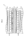
- FIG. 2 that is a partially enlarged view of FIG. 1
- current-collecting meshes (wools) 30 made of metal are interposed and filled between each space formed between the adjacent thin plate member 10 and the (partitioning plate portion) of the support member 20.
- the upper and lower ends of each mesh 30 are in contact with current-collecting sintered films 40 made of porous metal formed on the upper and lower surfaces of each thin plate member 10 and the upper and lower surfaces of the partitioning plate portion of the support member 20. Accordingly, electrons produced by a power generation reaction of each thin plate member 10 can be taken out to the outside through the sintered film 40, mesh 30, and support member 20.
- the meshes 30 are filled in the entire area of each space in FIG. 2 , the meshes 30 may be filled in a part of each space.
- the sintered film 40 is formed on the entire area on the upper and lower surfaces of the partitioning plate portion of each support member 20 in FIG. 2 , the sintered film 40 may be formed only at a part of the upper and lower surfaces of each partitioning plate portion.
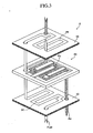
- fuel is supplied to a fuel flow path Pf formed between the upper surface of the thin plate member 10 (at the side of the later-described fuel electrode layer 12) and the lower surface (of the partitioning plate portion) of the support member 20, and air is supplied to an air flow path Pa formed between the lower surface of the thin plate member 10 (at the side of the later-described air electrode layer 13) and the upper surface (of the partitioning plate portion) of the support member 20, whereby power generation on the basis of the chemical equations (1) and (2) shown below is performed.
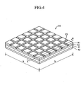
- FIG. 4 is a perspective view of the thin plate member 10
- FIG. 5 is a partial sectional view of the thin plate member 10 cut along the plane that includes 4 - 4 line parallel to the side having the length b and is perpendicular to the plane of the thin plate member 10.
- the thin plate member 10 is a sintered plate member having a square planar shape.
- the lengths a, b of one side are not less than 5 mm and not more than 200 mm.
- the thickness of the thin plate member 10 is not less than 24 ⁇ m and not more than 360 ⁇ m. Specifically, the thin plate member 10 is extremely thin and is easy to be warped.
- the thin plate member 10 includes an electrolyte layer (solid electrolyte layer) 11, a fuel electrode layer 12 laminated and formed on the upper surface (one surface) of the electrolyte layer 11, and an air electrode layer 13 laminated and formed on the lower surface (other surface) of the electrolyte layer 11.
- the fuel electrode layer 12 is a layer to which a fuel gas in the fuel flow path Pf is supplied from its upper surface
- the air electrode layer 13 is a layer to which air in the air flow path Pa is supplied from its lower surface.
- a porous layer 14 and a terminal 15 are laminated and formed on the upper surface (one surface) of the fuel electrode layer 12.
- the terminal 15 is formed so as to be in a lattice in plan view (see FIG. 4 ) and so as to have a side sectional face formed into a rectangle (see FIG. 5 ).
- the porous layer 14 is formed all over (except for the vicinity of the side face of the terminal 15) the remaining portion of the upper surface of the fuel electrode layer 12 where the terminal 15 is not formed.
- the height of the terminal 15 is slightly greater than the thickness of the porous layer 14.
- the sintered film 40 (see FIG. 2 ) is formed on the upper surface of the porous layer 14 and the upper surface of the terminal 15. Therefore, the terminal 15 can take out electrons, which are produced by the power generation reaction of the thin plate member 10, to the outside through the sintered film 40, mesh 30, and support member 20.
- the porous layer 14 is formed so as to prevent the warp on the thin plate member 10 as described later.
- the electrolyte layer 11 is a dense sintered body of YSZ (yttria-stabilized zirconia) serving as a ceramic layer.
- the fuel electrode layer is a sintered body made of Ni - YSZ serving as a porous electrode layer.
- the air electrode layer 13 is a sintered body made of LSM (La(Sr)Mn03: lanthanum strontium manganate) - YSZ serving as a porous electrode layer.
- the average thermal expansion coefficients of the electrolyte layer 11, fuel electrode layer 12, and air electrode layer 13 from room temperature to 1000 °C are approximately 10.8 ppm/K, 12.5 ppm/K, and 11 (10.8) ppm/K.
- the thermal expansion coefficient of the fuel electrode layer 12 is greater than the thermal expansion coefficient of the electrolyte layer 11, and the thermal expansion coefficient of the air electrode layer 13 is (generally) equal to the thermal expansion coefficient of the electrolyte layer 11.
- the porous layer 14 is a porous and insulating sintered body made of, for example, zircon.
- the porosity (the ratio of the volume of pores with respect to the whole) of the porous layer 14 is 10 to 80 %. Preferably, it is 20 to 70 % (30 to 60 %).
- the electrical resistance of the porous layer 14 at 800 °C is 10 4 to 10 5 ⁇ ⁇ m.
- the average thermal expansion coefficient of the porous layer 14 from room temperature to 1000 °C is approximately 4.2 ppm/K. Specifically, the thermal expansion coefficient of the porous layer 14 is smaller than the thermal expansion coefficient of the fuel electrode layer 12.
- the thermal expansion coefficient of the fuel electrode layer 12 is greater than the thermal expansion coefficient of the electrolyte layer 11, and the thermal expansion coefficient of the porous layer 14 is smaller than the thermal expansion coefficient of the fuel electrode layer 12 (and the electrolyte layer 11). Accordingly, the deformation direction of the thin plate member 10 based upon the internal stress caused by the difference in the thermal expansion coefficient between the electrolyte layer 11 and the fuel electrode layer 12 and the deformation direction of the thin plate member 10 based upon the internal stress caused by the difference in the thermal expansion coefficient between the fuel electrode layer 12 and the porous layer 14 can be made reverse to each other. As a result, the warp of the whole thin plate member 10 caused by the internal stress based upon the difference in the thermal expansion coefficient between the layers can be reduced.
- the porous layer 14 interposed between the fuel gas flow path Pf (see FIG. 3 ) and the fuel electrode layer 12 is made of a porous member. Therefore, the flow path of the fuel gas from the fuel gas flow path Pf to the upper surface of the fuel electrode layer 12 can sufficiently be secured. Accordingly, the circulation of the fuel gas to the upper surface of the fuel electrode layer 12 is difficult to be hindered. Consequently, the permeability of the fuel gas in the thin plate member 10 (unit cell) can be secured, thereby preventing the reduction in the power generation efficiency of the fuel cell A.
- the ratio of the area occupied by the porous layer 14 with respect to the whole thin plate member 10 is not less than 50 % in plan view. Therefore, the above-mentioned effect of reducing the warp on the thin plate member 10 provided by the porous layer 14 can uniformly and sufficiently be demonstrated.
- the existence region of the terminal 15 in the area of the whole thin plate member 10 is extremely uniformly arranged in plan view. Specifically, in any square regions in plan view that are a part of the whole thin plate member 10 and have the area of 50 % of the whole area of the thin plate member 10 in plan view, the ratio of the area occupied by the terminal 15 with respect to the square region in plan view is not less than 3 % and not more than 50 %.
- the porous layer 14 is formed generally all over the remaining portion (on the portion not less than 95 %) of the upper surface of the fuel electrode layer 12 where the terminal 15 is not formed. Specifically, the existence region of the porous layer 14 is extremely uniformly arranged even in the region of the whole thin plate member 10. As a result, the effect of reducing the warp on the thin plate member 10 provided by the porous layer 14 can extremely uniformly and sufficiently be demonstrated.
- the existence region of the terminal 15 is extremely uniformly arranged in the region of the whole thin plate member 10, the sum of the outer peripheries of the region (aforesaid terminal contact region) that are in contact with the (root) of the terminal 15 on the upper surface of the fuel electrode layer 12 is great.
- the fuel gas entering the inside of the fuel electrode layer 12 from the region, excluding the terminal 15, of the thin plate member 10 in plan view has a characteristic of moving into the region where the terminal 15 is present at the inside of the fuel electrode layer 12 in plan view (the above-mentioned diffusion phenomenon). This means that, as the sum of the outer peripheries of the terminal contact region increases, the diffusion phenomenon becomes more noticeable.
- the fuel gas can more uniformly reach the upper surface of the electrolyte layer 11 according to the present embodiment.
- the power generation efficiency of the fuel cell A can be further enhanced in case where the total area of the terminal 15 is constant in plan view (e.g., in case where the gas permeability is constant).
- the ratio of the area occupied by the terminal 15 is not less than 3 % and not more than 50 %" is determined considering the tendency in which the gas permeability increases as the ratio of the area of the terminal 15 decreases, and the tendency in which the internal resistance of the thin plate member 10 decreases as the ratio of the area of the terminal 15 increases.
- the thickness of the electrolyte layer 11 the thickness of the fuel electrode layer 12 and the thickness of the air electrode layer 13 are 15 to 50 ⁇ m, 3 to 50 ⁇ m, and 3 to 50 ⁇ m, respectively in the thin plate member 10 (i.e., the thin plate member 10 is supported by the electrolyte layer 11), and the difference in the thermal expansion coefficient between the fuel electrode layer 12 and the porous layer 14 is 4 to 9.5 ppm.K.
- FIG. 6 shows a result of the experiment in which samples (cells) of the thin plate member 10 having the electrolyte layer 11 with a thickness of 30 ⁇ m, fuel electrode layer 12 with a thickness of 15 ⁇ m, air electrode layer 13 with a thickness of 15 ⁇ m, and porous layer 14 made of zircon are manufactured as one example of the thin plate member 10, wherein the combinations of the thickness and the porosity of the porous layer 14 are different in each sample, and the power generation characteristic and the warp state after the sintering are evaluated for every sample.
- the output density (mW/cm 2 ) of the cell output at the rated output (0.7 V) at 800 °C is employed as the power generation characteristic.
- the smaller output density means the reduced gas permeability (permeability of the fuel gas).
- the warp is great, so that the evaluation is impossible. It is considered that this is because the rigidity of the porous layer 14 is insufficient, and hence, the warp reducing effect is insufficient, since the thickness of the porous layer 14 is too small.
- the thickness of the porous layer 14 is not less than 10 ⁇ m, the warp reducing effect can sufficiently be demonstrated. It is to be noted that, when the thickness of the porous layer 14 is not less than 40 ⁇ m, the output density becomes small. It is considered that this is because the gas permeability is reduced, since the thickness of the porous layer 14 is too great.
- the output density becomes small. It is considered that this is because the gas permeability is reduced since the porosity of the porous layer 14 is too small.
- the porosity of the porous layer 14 is not less than 20 %, sufficient output density of not less than 300 (mW/cm 2 ) can be obtained. It is to be noted that, when the porosity of the porous layer 14 is not less than 75 %, the warp becomes great. It is considered that this is because the rigidity of the porous layer 14 is insufficient, and hence, the warp reducing effect is insufficient, since the porosity of the porous layer 14 is too great.
- the thickness of the porous layer 14 is 10 to 30 ⁇ m, and the porosity thereof is 20 to 70 %.
- the warp reducing effect can sufficiently be demonstrated while securing the permeability of the gas (fuel gas). It is estimated that this is based upon the fact that, as the porosity of the porous layer 14 increases or as the thickness of the porous layer 14 is decreased, there is a tendency of enhancing the gas permeability, and as the porosity of the porous layer 14 increases, there is a tendency of increasing the thickness of the porous layer 14 necessary for sufficiently demonstrating the warp reducing effect.
- the thickness of the electrolyte layer 11 the thickness of the fuel electrode layer 12 and the thickness of the air electrode layer 13 are 1 to 10 ⁇ m, 50 to 250 ⁇ m, and 3 to 50 ⁇ m, respectively in the thin plate member 10 (i.e., the thin plate member 10 is supported by the fuel electrode layer 12), and the difference in the thermal expansion coefficient between the fuel electrode layer 12 and the porous layer 14 is 4 to 9.5 ppm.K.
- FIG. 7 shows a result of the experiment in which samples (cells) of the thin plate member 10 having the electrolyte layer 11 with a thickness of 3 ⁇ m, fuel electrode layer 12 with a thickness of 90 ⁇ m, air electrode layer 13 with a thickness of 15 ⁇ m, and porous layer 14 made of zircon are manufactured as one example of the thin plate member 10, wherein the combinations of the thickness and the porosity of the porous layer 14 are different in each sample, and the power generation characteristic and the warp state after the sintering are evaluated for every sample.
- the output density (mW/cm 2 ) of the cell output at the rated output (0.7 V) at 800 °C is employed as the power generation characteristic, like the case of FIG. 6 .
- the warp is great, so that the evaluation is impossible. It is considered that this is because the rigidity of the porous layer 14 is insufficient, and hence, the warp reducing effect is insufficient, since the thickness of the porous layer 14 is too small.
- the thickness of the porous layer 14 is not less than 10 ⁇ m, the warp reducing effect can sufficiently be demonstrated. It is to be noted that, when the thickness of the porous layer 14 is not less than 60 ⁇ m, the output density becomes small. It is considered that this is because the gas permeability is reduced, since the thickness of the porous layer 14 is too great.
- the output density becomes small. It is considered that this is because the gas permeability is reduced since the porosity of the porous layer 14 is too small.
- the porosity of the porous layer 14 is not less than 20 %, sufficient output density of not less than 700 (mW/cm 2 ) can be obtained. It is to be noted that, when the porosity of the porous layer 14 is not less than 75 %, the warp becomes great. It is considered that this is because the rigidity of the porous layer 14 is insufficient, and hence, the warp reducing effect is insufficient, since the porosity of the porous layer 14 is too great.
- the thickness of the porous layer 14 is 10 to 50 ⁇ m, and the porosity thereof is 20 to 70 %.
- the porous layer 14 which is made of porous insulating member and has a thermal expansion coefficient smaller that the thermal expansion coefficient of the fuel electrode layer 12, is laminated and formed on the upper surface of the fuel electrode layer 12, whereby the warp on the thin plate member 10 is prevented and the gas permeability can sufficiently be secured.
- porous layer 14 and the terminal 15 are extremely uniformly arranged in plan view. As a result, the effect of reducing the warp on the thin plate member 10 provided by the porous layer 14 can extremely uniformly and sufficiently be demonstrated.
- a square sheet (a layer serving as the fuel electrode layer 12) is formed on the upper surface of a square ceramic sheet (a layer serving as the electrolyte layer 11) by a printing method, and a pattern (a layer serving as the porous layer 14) having a shape corresponding to the porous layer 14 is formed thereon by a printing method.
- the resultant is sintered at 1400 °C for one hour.
- a square sheet (a layer serving as the air electrode layer 13) is formed on the lower surface of the sintered body by a printing method, and the resultant is sintered at 1200 °C for one hour.
- a pattern (a layer serving as the terminal 15) having a shape corresponding to the terminal 15 is formed on the upper surface of the sintered body, and the resultant is sintered at 1000 °C for one hour.
- the thin plate member 10 shown in FIGS. 4 and 5 is manufactured.
- the present invention is not limited to the first embodiment, and various modifications are possible within the scope of the present invention.
- a slight gap is formed between the side face of the porous layer 14 and the side face of the terminal 15 at the side sectional surface as shown in FIG. 5 according to the first embodiment.
- the side faces of the porous layer 14 and the terminal 15 are brought into contact with each other at the side sectional surface as shown in FIG. 8 .
- the side sectional surface of the terminal 15 is formed into a rectangle in the first embodiment, the side sectional surface of the terminal 15 may be formed into a T-like shape as shown in FIG. 9 . Further, as shown in FIG. 10 , the upper surfaces of the porous layer 14 and the terminal 15 may be formed into a convex shape at the side sectional surface.
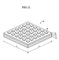
- the terminal 15 is formed in a lattice (see FIG. 4 ), in plan view, in the first embodiment, the terminal 15 is formed into plural islands, in plan view, aligned in the longitudinal direction and widthwise direction so as to be apart from each other as shown in FIG. 11 .
- the plural terminals 15 are arranged and formed in such a manner that the area of the whole thin plate member 10 in plan view is not less than 25 mm 2 and not more than 40000 mm 2 , four or more terminals 15 are formed so as to be apart from each other, and each of the minimum spaces in plan view between each terminal 15 and the other terminals is not less than 0.5 mm and not more than 10 mm.
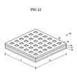
- the terminal 15 may be formed in a lattice having a wider frame than that in the first embodiment, in plan view, as shown in FIG. 12 . Further, the terminal 15 may be composed of plural islands arranged so as to be apart from each other and bridges that connect the adjacent islands as shown in FIG. 13 .
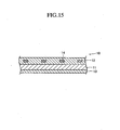
- FIGS. 14 and 15 illustrate the example in which the porous layer 14 is formed in a lattice in plan view, for example.
- the ratio of the area occupied by the porous layer 14 with respect to the whole thin plate member 10 is not less than 50 %. Further, it can be configured such that the thickness of the solid electrolyte layer 11 is 15 to 50 ⁇ m, the thickness of the fuel electrode layer 12 is 3 to 50 ⁇ m, the thickness of the air electrode layer 13 is 3 to 50 ⁇ m, and the difference in the thermal expansion coefficient between the porous layer 14 and the fuel electrode layer 12 is 4 to 9.5 ppm/K.
- the thickness of the solid electrolyte layer 11 is 1 to 10 ⁇ m
- the thickness of the fuel electrode layer 12 is 50 to 250 ⁇ m
- the thickness of the air electrode layer is 3 to 50 ⁇ m
- the difference in the thermal expansion coefficient between the porous layer 14 and the fuel electrode layer 12 is 4 to 9.5 ppm/K.
- FIG. 16 is a perspective view of the thin plate member 10 according to the second embodiment
- FIG. 17 is a partial sectional view of the thin plate member 10 cut along the plane that includes 12-12 line parallel to the side having the length a and is perpendicular to the plane of the thin plate member 10 in FIG. 16 .
- the thin plate member 10 according to the second embodiment is different from the thin plate member in the first embodiment in that a porous layer 16 made of a porous insulating member and having a thermal expansion coefficient greater than the thermal expansion coefficient of the air electrode layer 13 and a terminal 17 are formed at the lower surface of the air electrode layer 13.
- a porous layer 16 made of a porous insulating member and having a thermal expansion coefficient greater than the thermal expansion coefficient of the air electrode layer 13 and a terminal 17 are formed at the lower surface of the air electrode layer 13.
- the thin plate member 10 is a sintered plate member having a square planar shape.
- the lengths a, b of one side are not less than 5 mm and not more than 200 mm.
- the thickness of the thin plate member 10 is not less than 24 ⁇ m and not more than 360 ⁇ m. Specifically, the thin plate member 10 is extremely thin and is easy to be deformed.
- the thin plate member 10 includes, like the first embodiment, an electrolyte layer 11, a fuel electrode layer 12 and an air electrode layer 13.
- the porous layer 16 and the terminal 17 are laminated and formed on the lower surface (other surface) of the air electrode layer 13.
- the terminal 17 is formed so as to be in a lattice in plan view (see FIG. 12 ) and so as to have a rectangle side face (see FIG. 13 ).
- the porous layer 16 is formed all over (except for the vicinity of the side face of the terminal 17) the remaining portion of the lower surface of the air electrode layer 13 where the terminal 17 is not formed.
- the height of the terminal 17 is slightly greater than the thickness of the porous layer 16.
- the sintered film 40 (see FIG. 2 ) is formed on the lower surface of the porous layer 16 and the lower surface of the terminal 17. Therefore, the terminal 17 can take out electrons, which are produced by the power generation reaction of the thin plate member 10, to the outside through the sintered film 40, mesh 30, and support member 20.
- the porous layer 16 is formed so as to prevent the warp on the thin plate member 10 as described later.
- the materials of the electrolyte layer 11, fuel electrode layer 12, and air electrode layer 13 are the same as those in the first embodiment. Specifically, the thermal expansion coefficient of the fuel electrode layer 12 is greater than the thermal expansion coefficient of the electrolyte layer 11, and the thermal expansion coefficient of the air electrode layer 13 is (generally) equal to the thermal expansion coefficient of the electrolyte layer 11.
- the porous layer 16 is a porous and insulating sintered body made of, for example, magnesia.
- the porosity (the ratio of the volume of pores with respect to the whole) of the porous layer 16 is 10 to 80 %. Preferably, it is 20 to 70 % (30 to 60 %).
- the electrical resistance of the porous layer 16 is 10 3 to 10 4 ⁇ ⁇ m.
- the average thermal expansion coefficient of the porous layer 16 from room temperature to 1000 °C is approximately 14.5 ppm/K. Specifically, the thermal expansion coefficient of the porous layer 16 is greater than the thermal expansion coefficient of the air electrode layer 13.
- the thermal expansion coefficient of the fuel electrode layer 12 is greater than the thermal expansion coefficient of the electrolyte layer 11
- the thermal expansion coefficient of the porous layer 16 is greater than the thermal expansion coefficient of the air electrode layer 13 (and the electrolyte layer 11). Accordingly, the deformation direction of the thin plate member 10 based upon the internal stress caused by the difference in the thermal expansion coefficient between the electrolyte layer 11 and the fuel electrode layer 12 and the deformation direction of the thin plate member 10 based upon the internal stress caused by the difference in the thermal expansion coefficient between the air electrode layer 13 and the porous layer 16 can be made reverse to each other. As a result, the warp of the whole thin plate member 10 caused by the internal stress based upon the difference in the thermal expansion coefficient between the layers can be reduced.
- the porous layer 16 interposed between the air flow path Pa (see FIG. 3 ) and the air electrode layer 13 is made of a porous member. Therefore, the flow path of the air from the air flow path Pa to the lower surface of the air electrode layer 13 can sufficiently be secured. Accordingly, the circulation of the air to the lower surface of the air electrode layer 13 is difficult to be hindered. Consequently, the permeability of the air in the thin plate member 10 (unit cell) can be secured, thereby preventing the reduction in the power generation efficiency of the fuel cell A.
- the ratio of the area occupied by the porous layer 16 with respect to the whole thin plate member 10 is not less than 50 % in plan view. Therefore, the above-mentioned effect of reducing the warp on the thin plate member 10 provided by the porous layer 16 can uniformly and sufficiently be demonstrated.
- the existence region of the terminal 17 in the area of the whole thin plate member 10 is extremely uniformly arranged. Specifically, in any square regions in plan view that are a part of the whole thin plate member 10 and have the area of 50 % of the whole area of the thin plate member 10 in plan view, the ratio of the area occupied by the terminal 17 with respect to the square region in plan view is not less than 3 % and not more than 50 %.
- the porous layer 16 is formed generally all over the remaining portion (on the portion not less than 95 %) of the lower surface of the air electrode layer 13 where the terminal 17 is not formed. Specifically, the existence region of the porous layer 16 is extremely uniformly arranged even in the region of the whole thin plate member 10. As a result, the effect of reducing the warp on the thin plate member 10 provided by the porous layer 16 can extremely uniformly and sufficiently be demonstrated.
- the existence region of the terminal 17 is extremely uniformly arranged in the region of the whole thin plate member 10, the sum of the outer peripheries of the region (aforesaid terminal contact region) that is in contact with the (root) of the terminal 17 on the lower surface of the air electrode layer 13 is great. Specifically, the aforesaid diffusion phenomenon becomes more noticeable like the first embodiment. Therefore, according to the second embodiment, the air can reach the lower surface of the electrolyte layer 11 more uniformly. As a result, the power generation efficiency of the fuel cell A can be further enhanced in case where the total area of the terminal 17 is constant in plan view (e.g., in case where the gas permeability is constant).
- the ratio of the area occupied by the terminal 17 is not less than 3 % and not more than 50 %" is determined considering the tendency in which the gar permeability increases as the ratio of the area of the terminal 17 decreases, and the tendency in which the internal resistance of the thin plate member 10 decreases as the ratio of the area of the terminal 17 increases.
- the thickness of the electrolyte layer 11 the thickness of the fuel electrode layer 12 and the thickness of the air electrode layer 13 are 15 to 50 ⁇ m, 3 to 50 ⁇ m, and 3 to 50 ⁇ m, respectively in the thin plate member 10 (i.e., the thin plate member 10 is supported by the electrolyte layer 11), and the difference in the thermal expansion coefficient between the air electrode layer 13 and the porous layer 16 is 1.7 to 3.5 ppm.K.
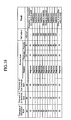
- FIG. 18 shows a result of the experiment in which samples (cells) of the thin plate member 10 having the electrolyte layer 11 with a thickness of 30 ⁇ m, fuel electrode layer 12 with a thickness of 15 ⁇ m, air electrode layer 13 with a thickness of 15 ⁇ m, and porous layer 16 made of magnesia are manufactured as one example of the thin plate member 10, wherein the combinations of the thickness and the porosity of the porous layer 16 are different in each sample, and the power generation characteristic and the warp state after the sintering are evaluated for every sample.
- the output density (mW/cm 2 ) of the cell output at the rated output (0.7 V) at 800 °C is employed as the power generation characteristic, like the case of FIG. 6 .
- the warp is great, so that the evaluation is impossible. It is considered that this is because the rigidity of the porous layer 16 is insufficient, and hence, the warp reducing effect is insufficient, since the thickness of the porous layer 16 is too small.
- the thickness of the porous layer 16 is not less than 20 ⁇ m, the warp reducing effect can sufficiently be demonstrated. It is to be noted that, when the thickness of the porous layer 16 is not less than 50 ⁇ m, the output density becomes small. It is considered that this is because the gas permeability is reduced, since the thickness of the porous layer 16 is too great.
- the output density becomes small. It is considered that this is because the gas permeability is reduced since the porosity of the porous layer 16 is too small.
- the porosity of the porous layer 16 is not less than 20 %, sufficient output density of not less than 300 (mW/cm 2 ) can be obtained. It is to be noted that, when the porosity of the porous layer 16 is not less than 75 %, the warp becomes great. It is considered that this is because the rigidity of the porous layer 16 is insufficient, and hence, the warp reducing effect is insufficient, since the porosity of the porous layer 16 is too great.
- the thickness of the porous layer 16 is 20 to 40 ⁇ m, and the porosity thereof is 20 to 70 %.
- the warp reducing effect can sufficiently be demonstrated while securing the permeability of the gar (air). It is estimated that this is based upon the fact that, as the porosity of the porous layer 16 increases or as the thickness of the porous layer 16 is decreased, there is a tendency of enhancing the gas permeability, and as the porosity of the porous layer 16 increases, there is a tendency of increasing the thickness of the porous layer 16 necessary for sufficiently demonstrating the warp reducing effect.
- the thickness of the electrolyte layer 11 the thickness of the fuel electrode layer 12 and the thickness of the air electrode layer 13 are 1 to 10 ⁇ m, 50 to 250 ⁇ m, and 3 to 50 ⁇ m, respectively in the thin plate member 10 (i.e., the thin plate member 10 is supported by the fuel electrode layer 12), and the difference in the thermal expansion coefficient between the air electrode layer 13 and the porous layer 16 is 1.7 to 3.5 ppm.K.
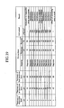
- FIG. 19 shows a result of the experiment in which samples (cells) of the thin plate member 10 having the electrolyte layer 11 with a thickness of 3 ⁇ m, fuel electrode layer 12 with a thickness of 90 ⁇ m, air electrode layer 13 with a thickness of 15 ⁇ m, and porous layer 16 made of magnesia are manufactured as one example of the thin plate member 10, wherein the combinations of the thickness and the porosity of the porous layer 16 are different in each sample, and the power generation characteristic and the warp state after the sintering are evaluated for every sample.
- the output density (mW/cm 2 ) of the cell output at the rated output (0.7 V) at 800 °C is employed as the power generation characteristic, like the case of FIG. 6 .
- the warp is great, so that the evaluation is impossible. It is considered that this is because the rigidity of the porous layer 16 is insufficient, and hence, the warp reducing effect is insufficient, since the thickness of the porous layer 16 is too small.
- the thickness of the porous layer 16 is not less than 20 ⁇ m, the warp reducing effect can sufficiently be demonstrated. It is to be noted that, when the thickness of the porous layer 16 is not less than 60 ⁇ m, the output density becomes small. It is considered that this is because the gas permeability is reduced, since the thickness of the porous layer 14 is too great.
- the output density becomes small. It is considered that this is because the gas permeability is reduced since the porosity of the porous layer 16 is too small.
- the porosity of the porous layer 16 is not less than 20 %, sufficient output density of not less than 650 (mW/cm 2 ) can be obtained. It is to be noted that, when the porosity of the porous layer 16 is not less than 75 %, the warp becomes great. It is considered that this is because the rigidity of the porous layer 16 is insufficient, and hence, the warp reducing effect is insufficient, since the porosity of the porous layer 16 is too great.
- the thickness of the porous layer 16 is 20 to 50 ⁇ m, and the porosity thereof is 20 to 70 %.
- the porous layer 16 which is made of porous insulating member and has a thermal expansion coefficient greater that the thermal expansion coefficient of the air electrode layer 13, is laminated and formed on the lower surface of the air electrode layer 13, whereby the warp on the thin plate member 10 is prevented and the gas permeability can sufficiently be secured.
- porous layer 16 and the terminal 17 are extremely uniformly arranged in plan view. As a result, the effect of reducing the warp on the thin plate member 10 provided by the porous layer 16 can extremely uniformly and sufficiently be demonstrated.
- a square sheet (a layer serving as the fuel electrode layer 12) is formed on the upper surface of a square ceramic sheet (a layer serving as the electrolyte layer 11) by a printing method, and the resultant is sintered at 1400 °C for one hour.
- a square sheet (a layer serving as the air electrode layer 13) is formed on the lower surface of the sintered body by a printing method, and a pattern (a layer serving as the porous layer 16) having a shape corresponding to the porous layer 16 is formed by a printing method.
- the resultant is sintered at 1200 °C for one hour.
- a pattern (a layer serving as the terminal 17) having a shape corresponding to the terminal 17 is formed on the lower surface of the sintered body, and the resultant is sintered at 1000 °C for one hour.
- the thin plate member 10 shown in FIGS. 16 and 17 is manufactured.
- the present invention is not limited to the second embodiment, and various modifications are possible within the scope of the present invention.
- a slight gap is formed between the side face of the porous layer 16 and the side face of the terminal 17 at the side sectional surface as shown in FIG. 17 according to the second embodiment.
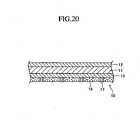
- the side faces of the porous layer 16 and the terminal 17 are brought into contact with each other at the side sectional surface as shown in FIG. 20 .
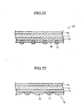
- the side sectional surface of the terminal 17 is formed into a rectangle in the second embodiment, the side sectional surface of the terminal 17 may be formed into a T-like shape as shown in FIG. 21 . Further, as shown in FIG. 22 , the upper surfaces of the porous layer 16 and the terminal 17 may be formed into a convex shape at the side sectional surface.
- the terminal 17 is formed in a lattice (see FIG. 16 ), in plan view, in the second embodiment, the terminal 17 is formed into plural islands, in plan view, aligned in the longitudinal direction and widthwise direction so as to be apart from each other as shown in FIG. 23 .
- the plural terminals 17 are arranged and formed in such a manner that the area of the whole thin plate member 10 is not less than 25 mm 2 and not more than 40000 mm 2 in plan view, four or more terminals 17 are formed so as to be apart from each other, and each of the minimum spaces between each terminal and the other terminals is not less than 0.5 mm and not more than 10 mm.
- the terminal 17 may be formed in a lattice having a wider frame than that in the second embodiment, in plan view, as shown in FIG. 24 . Further, in plan view, the terminal 17 may be composed of plural islands arranged so as to be apart from each other and bridges that connect the adjacent islands as shown in FIG. 25 .
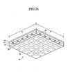
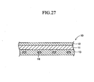
- FIGS. 26 and 27 illustrate the example in which the porous layer 16 is formed in a lattice in plan view, for example.
- the ratio of the area occupied by the porous layer 16 with respect to the whole thin plate member 10 is not less than 50 %. Further, it can be configured such that the thickness of the solid electrolyte layer 11 is 15 to 50 ⁇ m, the thickness of the fuel electrode layer 12 is 3 to 50 ⁇ m, the thickness of the air electrode layer 13 is 3 to 50 ⁇ m, and the difference in the thermal expansion coefficient between the porous layer 14 and the fuel electrode layer 12 is 1.7 to 3.5 ppm/K.
- the thickness of the solid electrolyte layer 11 is 1 to 10 ⁇ m
- the thickness of the fuel electrode layer 12 is 50 to 250 ⁇ m
- the thickness of the air electrode layer 13 is 3 to 50 ⁇ m
- the difference in the thermal expansion coefficient between the porous layer 16 and the air electrode layer 13 is 1.7 to 3.5 ppm/K.
- the porous layer 14, which is made of porous insulating member and has a thermal expansion coefficient smaller than the thermal expansion coefficient of the fuel electrode layer 12, may be formed on the upper surface of the fuel electrode layer 12, and the porous layer 16, which is made of porous insulating member and has a thermal expansion coefficient greater than the thermal expansion coefficient of the air electrode layer 13, may be formed on the lower surface of the air electrode layer 13.
Landscapes
- Life Sciences & Earth Sciences (AREA)
- Engineering & Computer Science (AREA)
- Manufacturing & Machinery (AREA)
- Sustainable Development (AREA)
- Sustainable Energy (AREA)
- Chemical & Material Sciences (AREA)
- Chemical Kinetics & Catalysis (AREA)
- Electrochemistry (AREA)
- General Chemical & Material Sciences (AREA)
- Fuel Cell (AREA)
- Inert Electrodes (AREA)
Claims (8)
- Elément formant plaque mince (10) pour une pile à combustible à oxyde solide comprenant :une couche d'électrolyte solide (11) ;une première couche d'électrode (12) formée sur une première surface de la couche d'électrolyte solide (11), ayant un coefficient de dilatation thermique supérieur à celui de la couche d'électrolyte solide (11), et appropriée pour recevoir une alimentation en combustible gazeux ; etune deuxième couche d'électrode (13) formée sur la deuxième surface de la couche d'électrolyte solide (11), et appropriée pour recevoir une alimentation en oxyde gazeux,dans lequel l'un de I et II ci-dessous s'applique :I. soit(a) l'élément formant plaque mince (10) comprend une couche isolante poreuse (14) formée sur la surface de la première couche d'électrode (12) à distance de la couche d'électrolyte solide (11) et sous la forme d'un élément isolant poreux ayant un coefficient de dilatation thermique inférieur à celui de la première couche d'électrode, soit(b) une couche isolante poreuse (16) formée sur la surface de la deuxième couche d'électrode (13) à distance de la couche d'électrolyte solide (11) et sous la forme d'un élément isolant poreux ayant un coefficient de dilatation thermique supérieur à celui de la deuxième couche d'électrode (13), etdans lequel ladite couche d'électrolyte solide (11), lesdites première et deuxième couches d'électrode (12, 13) et ladite couche poreuse (14, 16) sont lamifiées et frittées, et l'épaisseur de l'élément formant plaque mince est inférieure ou égale à 360 µm,et dans lequel dans le cas (a) ci-dessus, soit (1) l'épaisseur de la couche d'électrolyte solide (11) est de 15 à 50 µm, l'épaisseur de la première couche d'électrode (12) est de 3 à 50 µm, l'épaisseur de la deuxième couche d'électrode (13) est de 3 à 50 µm, la différence du coefficient de dilatation thermique entre la couche poreuse (14) et la première couche d'électrode (12) est de 4 à 9,5 ppm/K, l'épaisseur de la couche poreuse (14) est de 10 à 30 µm, et la porosité de la couche poreuse (14) est de 20 à 70 %,soit(2) l'épaisseur de la couche d'électrolyte solide (11) est de 1 à 10 µm, l'épaisseur de la première couche d'électrode (12) est de 50 à 250 µm, l'épaisseur de la deuxième couche d'électrode (13) est de 3 à 50 µm, la différence du coefficient de dilatation thermique entre la couche poreuse (14) et la première couche d'électrode (12) est de 4 à 9,5 ppm/K, l'épaisseur de la couche poreuse (14) est de 10 à 50 µm, et la porosité de la couche poreuse (14) est de 20 à 70 %,
et dans le cas (b) ci-dessus, soit(3) l'épaisseur de la couche d'électrolyte solide (11) est de 15 à 50 µm, l'épaisseur de la première couche d'électrode (12) est de 3 à 50 µm, l'épaisseur de la deuxième couche d'électrode (13) est de 3 à 50 µm, la différence du coefficient de dilatation thermique entre la couche poreuse (16) et la deuxième couche d'électrode (13) est de 1,7 à 3,5 ppm/K, l'épaisseur de la couche poreuse (16) est 20 à 40 µm, et la porosité de la couche poreuse (16) est de 20 à 70 %, soit(4) l'épaisseur de la couche d'électrolyte solide (11) est de 1 à 10 µm, l'épaisseur de la première couche d'électrode (12) est de 50 à 250 µm, l'épaisseur de la deuxième couche d'électrode (13) est de 3 à 50 µm, la différence du coefficient de dilatation thermique entre la couche poreuse (16) et la deuxième couche d'électrode (13) est de 1,7 à 3,5 ppm/k, l'épaisseur de la couche poreuse (16) est de 20 à 50 µm, et la porosité de la couche poreuse (16) est de 20 à 70 %,II. lesdites première et deuxième couches d'électrode (12, 13) sont lamifiées et frittées, et
soit(c) une couche isolante poreuse (14) constituée d'un élément isolant poreux ayant un coefficient de dilatation thermique inférieur à celui de la première couche d'électrode (12) est intégré dans la première couche d'électrode (12), soit(d) une couche isolante poreuse (16) constituée d'un élément isolant poreux ayant un coefficient de dilatation thermique supérieur à celui de la deuxième couche d'électrode (13) est intégrée dans la deuxième couche d'électrode (16), dans lequel, dans le cas (c) ci-dessus, soit (5) l'épaisseur de la couche d'électrolyte solide (11) est de 15 à 50 µm, l'épaisseur de la première couche d'électrode (12) est de 3 à 50 µm, l'épaisseur de la deuxième couche d'électrode (13) est de 3 à 50 µm, et la différence du coefficient de dilatation thermique entre la couche poreuse (14) et la première couche d'électrode (12) est de 4 à 9,5 ppm/K,soit(6) l'épaisseur de la couche d'électrolyte solide (11) est de 1 à 10 µm, l'épaisseur de la première couche d'électrode (12) est de 50 à 250 µm, et l'épaisseur de la deuxième couche d'électrode (13) est de 3 à 50 µm, et la différence du coefficient de dilatation thermique entre la couche poreuse (14) et la première couche d'électrode (12) est de 4 à 9,5 ppm/K,
et dans le cas (d) ci-dessus, soit(7) l'épaisseur de la couche d'électrolyte solide (11) est de 15 à 50 µm, l'épaisseur de la première couche d'électrode (12) est de 3 à 50 µm, l'épaisseur de la deuxième couche d'électrode (13) est de 3 à 50 µm, et la différence du coefficient de dilatation thermique entre la couche poreuse (16) et la deuxième couche d'électrode (13) est de 1,7 à 3,5 ppm/K,
soit(8) l'épaisseur de la couche d'électrolyte solide (11) est de 1 à 10 µm, l'épaisseur de la première couche d'électrode (12) est de 50 à 250 µm, l'épaisseur de la deuxième couche d'électrode (13) est de 3 à 50 µm, et la différence du coefficient de dilatation thermique entre la couche poreuse (16) et la deuxième couche d'électrode (13) est de 1,7 à 3,5 ppm/K. - Elément formant plaque mince selon la revendication 1, dans lequel le rapport de l'aire occupée par la couche poreuse (14, 16) par rapport à l'élément formant plaque mince (10) entier en vue plane est supérieur ou égal à 50 %.
- Elément formant plaque mince selon la revendication 1 à 2, dans lequel le cas (a) s'applique et une borne d'électrode (15) pour prendre les électrons, qui sont produits par une réaction de génération d'énergie de l'élément formant plaque mince, vers l'extérieur est formée sur une partie de ladite surface de la première couche d'électrode (12) où la couche poreuse (14) n'est pas formée.
- Elément formant plaque mince selon la revendication 3, dans lequel, dans n'importe quelle région vue en vue plane qui fait partie de l'élément formant plaque mince entier ayant une aire égale à 50 % de celle de l'élément formant plaque mince entier vu en vue plane, le rapport de l'aire occupée par la borne (15) par rapport à la région est supérieur ou égal à 3 % et inférieur ou égal à 50 %.
- Elément formant plaque mince selon la revendication 4, dans lequel
l'aire de l'élément formant plaque mince entier en vue plane est supérieure ou égale à 25 mm2 et inférieure ou égale à 40000 mm2,
quatre ou plus desdites bornes (15) sont formées de manière à être espacées les unes des autres, et
chacun des espaces minimums en vue plane entre chaque dite borne (17) et les autres bornes (15) est supérieur ou égal à 0,5 mm et inférieur ou égal à 10 mm. - Elément formant plaque mince selon la revendication 1 ou 2, dans lequel le cas (b) s'applique et une borne d'électrode (17) pour prendre les électrons, qui sont produits par une réaction de génération d'énergie de l'élément formant plaque mince, vers l'extérieur est formée sur une partie de ladite surface de la deuxième couche d'électrode (13) où la couche poreuse (16) n'est pas formée.
- Elément formant plaque mince selon la revendication 6, dans lequel, dans n'importe quelle région vue en vue plane qui fait partie de l'élément formant plaque mince entier ayant une aire égale à 50 % de celle de l'élément formant plaque mince entier vu en vue plane, le rapport de l'aire occupée par la borne (17) par rapport à la région est supérieur ou égal à 3 % et inférieur ou égal à 50 %.
- Elément formant plaque mince selon la revendication 7, dans lequel
l'aire de l'élément formant plaque mince entier en vue plane est supérieure ou égale à 25 mm2 et inférieure ou égale à 40000 mm2,
quatre bornes (17) ou plus sont formées de manière à être espacées les unes des autres, et
chacun des espaces minimums en vue plane entre chaque dite borne (17) et les autres bornes (17) est supérieur ou égal à 0,5 mm et inférieur ou égal à 10 mm.
Applications Claiming Priority (2)
| Application Number | Priority Date | Filing Date | Title |
|---|---|---|---|
| JP2006288975 | 2006-10-24 | ||
| JP2007135651A JP5172207B2 (ja) | 2006-10-24 | 2007-05-22 | 固体酸化物型燃料電池の単セル用の薄板体 |
Publications (3)
| Publication Number | Publication Date |
|---|---|
| EP1919021A2 EP1919021A2 (fr) | 2008-05-07 |
| EP1919021A3 EP1919021A3 (fr) | 2009-05-06 |
| EP1919021B1 true EP1919021B1 (fr) | 2011-12-07 |
Family
ID=39145151
Family Applications (1)
| Application Number | Title | Priority Date | Filing Date |
|---|---|---|---|
| EP07254108A Not-in-force EP1919021B1 (fr) | 2006-10-24 | 2007-10-17 | Élément de plaque mince pour pile d'unité de pile à combustible d'oxyde solide |
Country Status (3)
| Country | Link |
|---|---|
| US (1) | US20080096076A1 (fr) |
| EP (1) | EP1919021B1 (fr) |
| JP (1) | JP5172207B2 (fr) |
Families Citing this family (19)
| Publication number | Priority date | Publication date | Assignee | Title |
|---|---|---|---|---|
| JP5378062B2 (ja) * | 2008-08-21 | 2013-12-25 | 日本碍子株式会社 | 固体酸化物型燃料電池の薄板体、及び固体酸化物型燃料電池 |
| JP4729121B2 (ja) | 2009-03-25 | 2011-07-20 | 株式会社日本触媒 | 固体酸化物形燃料電池用電解質シートならびに固体酸化物形燃料電池用セル |
| JP5631625B2 (ja) * | 2009-06-30 | 2014-11-26 | 日本碍子株式会社 | 固体酸化物形燃料電池 |
| JP4932960B1 (ja) * | 2010-12-20 | 2012-05-16 | 日本碍子株式会社 | 固体酸化物形燃料電池 |
| KR101278316B1 (ko) * | 2011-11-30 | 2013-06-25 | 삼성전기주식회사 | 고체산화물 연료 전지 |
| JP5869415B2 (ja) * | 2012-04-20 | 2016-02-24 | 日本特殊陶業株式会社 | 固体酸化物形燃料電池および燃料電池セル本体 |
| DE102013008473A1 (de) * | 2013-05-21 | 2014-11-27 | Plansee Composite Materials Gmbh | Brennstoffzelle |
| JP6125941B2 (ja) * | 2013-07-30 | 2017-05-10 | 日本特殊陶業株式会社 | 燃料電池セル及び燃料電池セルスタック |
| JP6125940B2 (ja) * | 2013-07-30 | 2017-05-10 | 日本特殊陶業株式会社 | 燃料電池セル及び燃料電池セルスタック |
| JP6268797B2 (ja) * | 2013-08-05 | 2018-01-31 | 日産自動車株式会社 | 固体電解質型燃料電池及び固体電解質型燃料電池スタック |
| JP2017522691A (ja) * | 2014-06-05 | 2017-08-10 | サン−ゴバン セラミックス アンド プラスティクス,インコーポレイティド | 扁平円筒形アノードを有する燃料電池 |
| JPWO2017199448A1 (ja) * | 2016-05-20 | 2019-03-22 | FCO Power株式会社 | インターコネクト構造及び固体酸化物形燃料電池 |
| DE102021117722A1 (de) * | 2021-07-08 | 2023-01-12 | Baumgartner & Lamperstorfer Instruments GmbH | Elektrode |
| WO2024101163A1 (fr) * | 2022-11-08 | 2024-05-16 | 日本碍子株式会社 | Cellule électrochimique |
| DE112023005093T5 (de) * | 2022-12-06 | 2025-10-23 | Ngk Insulators, Ltd. | Elektrochemische zelle |
| JP7705570B2 (ja) * | 2022-12-06 | 2025-07-09 | 日本碍子株式会社 | 電気化学セル |
| JP2025021673A (ja) * | 2023-08-01 | 2025-02-14 | 東芝エネルギーシステムズ株式会社 | 固体酸化物形電気化学セルスタック |
| WO2025104826A1 (fr) * | 2023-11-14 | 2025-05-22 | 日本碍子株式会社 | Cellule électrochimique |
| WO2025104823A1 (fr) * | 2023-11-14 | 2025-05-22 | 日本碍子株式会社 | Cellule électrochimique |
Family Cites Families (12)
| Publication number | Priority date | Publication date | Assignee | Title |
|---|---|---|---|---|
| JPH053037A (ja) * | 1990-10-03 | 1993-01-08 | Fuji Electric Co Ltd | 固体電解質型燃料電池 |
| JPH0668885A (ja) * | 1992-08-21 | 1994-03-11 | Ishikawajima Harima Heavy Ind Co Ltd | 固体電解質型燃料電池の製作方法 |
| JP3233807B2 (ja) * | 1995-02-15 | 2001-12-04 | 三菱重工業株式会社 | 固体電解質型燃料電池用基体材 |
| DE19960674B8 (de) * | 1999-12-15 | 2006-07-06 | Forschungszentrum Jülich GmbH | Substratgestützte Elektroden-Elektrolyt-Einheit |
| US7709124B2 (en) * | 2001-04-10 | 2010-05-04 | Northwestern University | Direct hydrocarbon fuel cells |
| NL1020985C2 (nl) * | 2002-07-03 | 2004-01-06 | Stichting Energie | Anodegedragen brandstofcel. |
| US7244526B1 (en) * | 2003-04-28 | 2007-07-17 | Battelle Memorial Institute | Solid oxide fuel cell anodes and electrodes for other electrochemical devices |
| JP4776930B2 (ja) * | 2004-04-28 | 2011-09-21 | 東京瓦斯株式会社 | 固体酸化物形燃料電池の支持基体 |
| JP4851692B2 (ja) * | 2004-05-31 | 2012-01-11 | 京セラ株式会社 | 固体電解質形燃料電池セルスタック、バンドル及び燃料電池 |
| JP4741815B2 (ja) * | 2004-06-30 | 2011-08-10 | 京セラ株式会社 | セルスタック及び燃料電池 |
| JP2006139966A (ja) * | 2004-11-10 | 2006-06-01 | Dainippon Printing Co Ltd | 固体酸化物形燃料電池 |
| US9985295B2 (en) * | 2005-09-26 | 2018-05-29 | General Electric Company | Solid oxide fuel cell structures, and related compositions and processes |
-
2007
- 2007-05-22 JP JP2007135651A patent/JP5172207B2/ja not_active Expired - Fee Related
- 2007-09-19 US US11/857,702 patent/US20080096076A1/en not_active Abandoned
- 2007-10-17 EP EP07254108A patent/EP1919021B1/fr not_active Not-in-force
Also Published As
| Publication number | Publication date |
|---|---|
| EP1919021A3 (fr) | 2009-05-06 |
| EP1919021A2 (fr) | 2008-05-07 |
| JP5172207B2 (ja) | 2013-03-27 |
| US20080096076A1 (en) | 2008-04-24 |
| JP2008135360A (ja) | 2008-06-12 |
Similar Documents
| Publication | Publication Date | Title |
|---|---|---|
| EP1919021B1 (fr) | Élément de plaque mince pour pile d'unité de pile à combustible d'oxyde solide | |
| JP5767297B2 (ja) | 積層型固体酸化物形燃料電池用スタック構造体、積層型固体酸化物形燃料電池及びその製造方法 | |
| US8703352B2 (en) | Solid oxide fuel cell having a closed recessed structure | |
| JP6208499B2 (ja) | 燃料電池セル又は電解セル、セルスタック装置、モジュールおよびモジュール収納装置 | |
| JP6122497B2 (ja) | セル、セルスタック装置、モジュールおよびモジュール収納装置 | |
| EP2680360A2 (fr) | Jonction pour la connexion électrique d'unités de production d'électricité faites de piles à combustible à oxyde solide | |
| US7927755B2 (en) | Ceramic thin plate member | |
| US9005844B2 (en) | Structure of solid oxide fuel cell | |
| US9954232B2 (en) | Fuel cell | |
| CN105474444A (zh) | 电池单元、电池堆装置、模块以及模块收纳装置 | |
| US9343769B2 (en) | Fuel cell and a method of manufacturing a fuel cell | |
| US11575137B2 (en) | Fuel cell stack and manufacturing method of the same | |
| US9722259B2 (en) | Ceramic substrate for electrochemical element, manufacturing method therefore, fuel cell, and fuel cell stack | |
| JP5501484B1 (ja) | 燃料電池のスタック構造体 | |
| US11251439B2 (en) | Fuel cell and fuel cell stack | |
| CN112470314B (zh) | 燃料电池单元及电池单元堆装置 | |
| JP2010129267A (ja) | 固体酸化物形燃料電池セル、燃料電池セルスタック装置、燃料電池モジュールおよび燃料電池装置 | |
| JP7270703B2 (ja) | セル | |
| US8709673B2 (en) | Fuel cell and a method of manufacturing a fuel cell | |
| JP6679652B2 (ja) | 燃料電池セル | |
| JP6507337B2 (ja) | 固体酸化物形燃料電池及びその製造方法 | |
| WO2018042479A1 (fr) | Cellule pour pile à combustible à oxyde solide, empilement de pile à combustible à oxyde solide, et pile à combustible à oxyde solide |
Legal Events
| Date | Code | Title | Description |
|---|---|---|---|
| PUAI | Public reference made under article 153(3) epc to a published international application that has entered the european phase |
Free format text: ORIGINAL CODE: 0009012 |
|
| 17P | Request for examination filed |
Effective date: 20071106 |
|
| AK | Designated contracting states |
Kind code of ref document: A2 Designated state(s): AT BE BG CH CY CZ DE DK EE ES FI FR GB GR HU IE IS IT LI LT LU LV MC MT NL PL PT RO SE SI SK TR |
|
| AX | Request for extension of the european patent |
Extension state: AL BA HR MK RS |
|
| PUAL | Search report despatched |
Free format text: ORIGINAL CODE: 0009013 |
|
| AK | Designated contracting states |
Kind code of ref document: A3 Designated state(s): AT BE BG CH CY CZ DE DK EE ES FI FR GB GR HU IE IS IT LI LT LU LV MC MT NL PL PT RO SE SI SK TR |
|
| AX | Request for extension of the european patent |
Extension state: AL BA HR MK RS |
|
| RIC1 | Information provided on ipc code assigned before grant |
Ipc: H01M 8/12 20060101AFI20080312BHEP Ipc: H01M 8/02 20060101ALI20090331BHEP |
|
| 17Q | First examination report despatched |
Effective date: 20090921 |
|
| AKX | Designation fees paid |
Designated state(s): DE FR GB |
|
| GRAP | Despatch of communication of intention to grant a patent |
Free format text: ORIGINAL CODE: EPIDOSNIGR1 |
|
| RAP1 | Party data changed (applicant data changed or rights of an application transferred) |
Owner name: NGK INSULATORS, LTD. |
|
| RIN1 | Information on inventor provided before grant (corrected) |
Inventor name: NATSUMI SHIMOGAWAC Inventor name: TSUTOMU NANATAKIC Inventor name: MAKOTO OHMORIC |
|
| GRAS | Grant fee paid |
Free format text: ORIGINAL CODE: EPIDOSNIGR3 |
|
| GRAA | (expected) grant |
Free format text: ORIGINAL CODE: 0009210 |
|
| AK | Designated contracting states |
Kind code of ref document: B1 Designated state(s): DE FR GB |
|
| REG | Reference to a national code |
Ref country code: GB Ref legal event code: FG4D |
|
| REG | Reference to a national code |
Ref country code: DE Ref legal event code: R096 Ref document number: 602007019190 Country of ref document: DE Effective date: 20120209 |
|
| PLBE | No opposition filed within time limit |
Free format text: ORIGINAL CODE: 0009261 |
|
| STAA | Information on the status of an ep patent application or granted ep patent |
Free format text: STATUS: NO OPPOSITION FILED WITHIN TIME LIMIT |
|
| 26N | No opposition filed |
Effective date: 20120910 |
|
| REG | Reference to a national code |
Ref country code: DE Ref legal event code: R097 Ref document number: 602007019190 Country of ref document: DE Effective date: 20120910 |
|
| GBPC | Gb: european patent ceased through non-payment of renewal fee |
Effective date: 20121017 |
|
| REG | Reference to a national code |
Ref country code: FR Ref legal event code: ST Effective date: 20130628 |
|
| PG25 | Lapsed in a contracting state [announced via postgrant information from national office to epo] |
Ref country code: GB Free format text: LAPSE BECAUSE OF NON-PAYMENT OF DUE FEES Effective date: 20121017 |
|
| PG25 | Lapsed in a contracting state [announced via postgrant information from national office to epo] |
Ref country code: FR Free format text: LAPSE BECAUSE OF NON-PAYMENT OF DUE FEES Effective date: 20121031 |
|
| REG | Reference to a national code |
Ref country code: DE Ref legal event code: R082 Ref document number: 602007019190 Country of ref document: DE Representative=s name: LEINWEBER & ZIMMERMANN, DE Ref country code: DE Ref legal event code: R081 Ref document number: 602007019190 Country of ref document: DE Owner name: MORIMURA SOFC TECHNOLOGY CO., LTD., KOMAKI-SHI, JP Free format text: FORMER OWNER: NGK INSULATORS, LTD., NAGOYA-CITY, AICHI-PREF., JP Ref country code: DE Ref legal event code: R082 Ref document number: 602007019190 Country of ref document: DE Representative=s name: LEINWEBER & ZIMMERMANN PATENTANWALTS-PARTG MBB, DE |
|
| PGFP | Annual fee paid to national office [announced via postgrant information from national office to epo] |
Ref country code: DE Payment date: 20230830 Year of fee payment: 17 |
|
| REG | Reference to a national code |
Ref country code: DE Ref legal event code: R119 Ref document number: 602007019190 Country of ref document: DE |
|
| PG25 | Lapsed in a contracting state [announced via postgrant information from national office to epo] |
Ref country code: DE Free format text: LAPSE BECAUSE OF NON-PAYMENT OF DUE FEES Effective date: 20250501 |