EP1919039A2 - Elément de connexion électrique, son procédé de fabrication et outil de moulage par injection - Google Patents
Elément de connexion électrique, son procédé de fabrication et outil de moulage par injection Download PDFInfo
- Publication number
- EP1919039A2 EP1919039A2 EP07020878A EP07020878A EP1919039A2 EP 1919039 A2 EP1919039 A2 EP 1919039A2 EP 07020878 A EP07020878 A EP 07020878A EP 07020878 A EP07020878 A EP 07020878A EP 1919039 A2 EP1919039 A2 EP 1919039A2
- Authority
- EP
- European Patent Office
- Prior art keywords
- housing
- plug
- fixing nut
- unit
- connection part
- Prior art date
- Legal status (The legal status is an assumption and is not a legal conclusion. Google has not performed a legal analysis and makes no representation as to the accuracy of the status listed.)
- Withdrawn
Links
Images


Classifications
-
- H—ELECTRICITY
- H01—ELECTRIC ELEMENTS
- H01R—ELECTRICALLY-CONDUCTIVE CONNECTIONS; STRUCTURAL ASSOCIATIONS OF A PLURALITY OF MUTUALLY-INSULATED ELECTRICAL CONNECTING ELEMENTS; COUPLING DEVICES; CURRENT COLLECTORS
- H01R43/00—Apparatus or processes specially adapted for manufacturing, assembling, maintaining, or repairing of line connectors or current collectors or for joining electric conductors
- H01R43/20—Apparatus or processes specially adapted for manufacturing, assembling, maintaining, or repairing of line connectors or current collectors or for joining electric conductors for assembling or disassembling contact members with insulating base, case or sleeve
- H01R43/24—Assembling by moulding on contact members
-
- H—ELECTRICITY
- H01—ELECTRIC ELEMENTS
- H01R—ELECTRICALLY-CONDUCTIVE CONNECTIONS; STRUCTURAL ASSOCIATIONS OF A PLURALITY OF MUTUALLY-INSULATED ELECTRICAL CONNECTING ELEMENTS; COUPLING DEVICES; CURRENT COLLECTORS
- H01R13/00—Details of coupling devices of the kinds covered by groups H01R12/70 or H01R24/00 - H01R33/00
- H01R13/46—Bases; Cases
- H01R13/502—Bases; Cases composed of different pieces
- H01R13/504—Bases; Cases composed of different pieces different pieces being moulded, cemented, welded, e.g. ultrasonic welding, or swaged together
-
- H—ELECTRICITY
- H01—ELECTRIC ELEMENTS
- H01R—ELECTRICALLY-CONDUCTIVE CONNECTIONS; STRUCTURAL ASSOCIATIONS OF A PLURALITY OF MUTUALLY-INSULATED ELECTRICAL CONNECTING ELEMENTS; COUPLING DEVICES; CURRENT COLLECTORS
- H01R13/00—Details of coupling devices of the kinds covered by groups H01R12/70 or H01R24/00 - H01R33/00
- H01R13/46—Bases; Cases
- H01R13/502—Bases; Cases composed of different pieces
- H01R13/508—Bases; Cases composed of different pieces assembled by a separate clip or spring
-
- H—ELECTRICITY
- H01—ELECTRIC ELEMENTS
- H01R—ELECTRICALLY-CONDUCTIVE CONNECTIONS; STRUCTURAL ASSOCIATIONS OF A PLURALITY OF MUTUALLY-INSULATED ELECTRICAL CONNECTING ELEMENTS; COUPLING DEVICES; CURRENT COLLECTORS
- H01R13/00—Details of coupling devices of the kinds covered by groups H01R12/70 or H01R24/00 - H01R33/00
- H01R13/64—Means for preventing incorrect coupling
-
- H—ELECTRICITY
- H01—ELECTRIC ELEMENTS
- H01R—ELECTRICALLY-CONDUCTIVE CONNECTIONS; STRUCTURAL ASSOCIATIONS OF A PLURALITY OF MUTUALLY-INSULATED ELECTRICAL CONNECTING ELEMENTS; COUPLING DEVICES; CURRENT COLLECTORS
- H01R13/00—Details of coupling devices of the kinds covered by groups H01R12/70 or H01R24/00 - H01R33/00
- H01R13/62—Means for facilitating engagement or disengagement of coupling parts or for holding them in engagement
- H01R13/622—Screw-ring or screw-casing
-
- H—ELECTRICITY
- H01—ELECTRIC ELEMENTS
- H01R—ELECTRICALLY-CONDUCTIVE CONNECTIONS; STRUCTURAL ASSOCIATIONS OF A PLURALITY OF MUTUALLY-INSULATED ELECTRICAL CONNECTING ELEMENTS; COUPLING DEVICES; CURRENT COLLECTORS
- H01R2201/00—Connectors or connections adapted for particular applications
- H01R2201/26—Connectors or connections adapted for particular applications for vehicles
Definitions
- the invention relates to an electrical connector part for a commercial vehicle with a contact plug-in unit comprising a housing with a plurality of plug contacts are connected to the leads of an electrical wiring harness, as well as with a waterproof and enclosing the housing and the umbilical, by encapsulation attached protective sheath, which with the Plug contacts provided housing comprises a mechanical coding for positionally directed mating with another, provided with corresponding plug contacts counter housing.
- the invention also relates to a method for producing such an electrical connector part, wherein first connecting wires of an electrical cable harness are connected to plug contacts of a housing of a contact plug-in unit.
- the invention also relates to a multi-part injection molding tool for producing a protective casing around a contact plug-in unit of such an electrical plug connection part with a cavity for receiving the contact plug-in unit.
- the invention finally relates to an electrical connector part for a commercial vehicle with a contact plug-in unit comprising a housing having a plurality of plug contacts are connected to the connecting wires of an electrical wiring harness, and with a rotatably held relative to the housing on this fixing nut, which in the ready-to-plug state with a corresponding connecting element of a mating contact unit cooperates, wherein the fixing nut comprises a fixing nut axially securing the retaining portion and a positive or non-positively cooperating with the corresponding connecting element of the mating contact unit connecting portion.
- Electrical connectors for commercial vehicles are well known.
- Such electrical connector parts each have a housing provided with a contact plug-in unit, in which an electrical cable leads.
- Corresponding connecting strands of the end of the cable harness are electrically conductively connected to the respective plug contacts of the housing within the contact plug-in unit.
- Such cable strands are often passed along the commercial vehicle through conduits and connected at one end by means of an electrical connector part with a vehicle electrical functional part such as a vehicle lamp unit, a wheel brake system or the like.
- the cable harness is preferably by means of a further electrical connector part connected to an electrical control unit.
- the object of the invention is to provide an electrical connector part of the type mentioned in each case, which enables safe manual assembly and fixation to appropriate parts of the commercial vehicle even in confined spaces.
- the object of the invention is also to provide a method and an injection molding tool of the type mentioned in each case, which enable the production of such a connector part by simple means.
- the protective casing is provided with at least one, resulting in alignment with the coding axially aligned marking.
- the object underlying the invention is achieved in that then the preassembled contact plug is inserted into a plastic injection mold and aligned with its housing in the circumferential direction and fixed so that a coding of the housing assumes a predetermined position, and that in one subsequent step by injection molding a protective plastic coating is applied, which is provided in the application with at least one of the zwangsposition elected coding resulting in axial alignment aligned mark.
- the generally known coding in the region of the housing provided with the plug contacts of the contact plug-in unit of the electrical connector part has a corresponding coding in the counter housing of the vehicle side arranged functional part.
- the codings serve to align the plug contacts and the mating contacts in the housing or in the mating housing, which are arranged asymmetrically within the end face of the housing, so exactly to one another that subsequently achieves a simple axial plug movement, the desired mechanical connector.
- the at least one marking in the area of the protective casing is consequently aligned in axial alignment. This means that, when providing only a single mark, it is aligned directly axially aligned with the coding.
- these can be aligned parallel to the alignment of the coding, whereby they are arranged in such a mirror-symmetrical manner to the axial alignment that, as a result, they are again directed in axial alignment.
- the alignment is provided such that they enclose the axial alignment of the coding symmetrically between them.
- the object is achieved in that a positioning part for positionally aligning a coding of the Contact plug unit is provided in the circumferential direction, and the cavity is provided with at least one profiling to obtain at least one mark in the protective sheath of the contact plug unit, wherein the position of the at least one profiling is chosen as a result axially aligned with the coding.
- the positioning part constitutes an insert part, which can be used as a separate component in the injection molding tool preferably consisting of two tool halves.
- the object is achieved in that the holding portion between a fixing nut axially securing fixing position and a release position in which the fixing nut can be axially removed from the housing, is arranged movable.
- the inventive solution it is possible to apply the fixing nut frontally on the contact plug unit.
- the invention was based on the finding that the relatively large diameter known fixable nuts held inseparably on the contact plug-in unit impeded or prevented the passage of connector parts, including corresponding electrical cable strands, through conduits on the commercial vehicle.
- the plug connection part including its electrical wiring harness, is first guided through a corresponding empty pipe of the utility vehicle without a fixing nut. Only after the passage through the empty tube, the fixing nut is placed by means of the detachable holding portion in a simple manner the front side on the contact plug unit. Despite cramped space thus easy installation and installation of appropriate cable strands with associated connector parts is possible.
- the holding portion is detachably arranged on the fixing nut.
- the holding section can thus be removed from the fixing nut and stored separately.
- the holding portion is shaped such that it is rotatably held in its fixing position together with the fixing nut on the housing.
- the holding portion forms a bearing for the fixing nut to allow a simple and quick screwing on the counterpart on the vehicle side arranged counter housing.
- the holding portion is designed like a clip and is preferably passed through corresponding openings in a jacket region of the fixing nut.
- the holding section on guide jaws which are provided with cylindrical section-shaped, inside sliding surfaces, which are designed to correspond to a cylindrical shell portion of the housing.
- the sliding surfaces in the axial direction of the housing on such a large guide length that tilting relative to the housing is avoided.
- the fixing nut is tilted strongly relative to the housing and thus would make it difficult to screw on the fixing nut in the assembled state of the contact plug-in unit.
- the relatively wide design of the clip-like running holding section by means of the large guide length is also advantageous in order to avoid that the holding section also referred to as retaining clip can tilt relative to the fixing nut.
- An unillustrated commercial vehicle in particular in the form of a truck, has a vehicle-mounted control box 1 with at least one electrical output, which is provided with a later referred to as mating housing mating contact unit 2.
- the electrical output is connected by means of a harness 8 with a vehicle fixed, electrical driving function unit.
- a driving function units are used in particular an electronic brake intervention control (ABS), but also vehicle tail lights and the like.
- ABS electronic brake intervention control
- the control box 1 is provided in particular in a truck in a front area of the vehicle, preferably in a cab area, whereas the driving function units are provided in the rear area of the truck or in the rear area of the wheel axle.
- corresponding cable strands 8 are passed through in the region of an underside of the truck fixed to the vehicle arranged empty tubes.
- Front side are the cable strands connected to connector parts 3, which are described in more detail below.
- a connector part 3 is shown, which is inserted in the assembled state of Figure 1 in the mating housing 2 of the control box 1 and fixed by a fixing nut 6 thereto.
- the counter housing 2 is provided on the outside with an external thread in a manner not shown.
- the fixing nut 6 has an internal thread which corresponds to the external thread of the counter housing 2.
- the cable harness 8 has a plurality of cables, which form the front side cable connection strands. These cable connecting leads, in the present exemplary embodiment seven, are electrically conductively connected to corresponding plug contacts 10 (FIG. 3) of a housing 4 of a contact plug-in unit of the plug connection part 3.
- the plug contacts 10 may be in the form of plugs or sockets, depending on the design of the corresponding mating housing 2. The basic structure of such a contact plug-in unit and thus of the housing 4 is well known.
- the housing 4 has in the region of the plug contacts 10 frontally a coding 9 in the region of an outer periphery of a hollow cylindrical plug portion of the housing 4, which is assigned to a mating plug portion of the mating housing 2 a corresponding coding, the nesting of housing 4 and mating housing 2 only in one single, predetermined circumferential alignment allows.
- This alignment and positioning corresponds exactly to the orientation in which the plug contacts 10 of the housing 4 and the corresponding plug contacts of the mating housing 2 are aligned with each other to allow a simple axial connector.
- the coding 9 is provided as a groove-like indentation on the cylindrical outer jacket of the plug-in section of the housing 4.
- the counter housing 2 in the region of its plug-in portion, the socket portion of the housing 4 on the outside encloses, a radially inwardly shaped counter profiling as coding, which pushes on the outside of the coding 9 of the housing 4, as soon as the housing 4 is inserted into the mating housing 2.
- the coding 9 of the plug connection part 3 is not recognizable when the fixing nut 6 is attached.
- the fixing nut 6 conceals the coding 9.
- the connector part 3 in the region of an axial provided behind the fixing nut 6 protective sheath 5 with a mark 7, which is formed exactly in axial alignment with the coding 9 ( Figure 4).
- the axial alignment is shown by the dot-dash line in Figure 4 and corresponds in the representation of Figure 4 an axial central longitudinal axis of the connector part.
- the protective sheath 5 is applied after the connection of the cable connection strands of the cable harness 8 with the plug contacts 10 within the housing 4 in a plastic injection molding process.
- the protective sheath 5 is made of a plastic material, preferably made of a thermoplastic elastomer material or a polyamide-based adhesive and serves to enclose the cable harness and the housing in the electrical connection area water-tight and gas-tight.
- Plastic injection molding can be carried out under low pressure or under high pressure, depending on the intended use and material selection.
- the housing 4 has, in addition to its cable connection area, in which open the cable connection strands of the cable harness 8 and the complete is covered by the protective sheath 5, a cylindrical guide portion 13 for the fixing nut 6. At a front end in the direction of insertion of the housing 4 connects to the cylindrical guide portion 13 a circumferential annular shoulder 12, which takes over the axial securing and support of the fixing nut 6 on the housing 4. On the provided with the coding 9 plug-in portion of the housing immediately after the annular shoulder 12, an elastic sealing ring 11 is provided.
- the housing 4 In order to ensure that the integrally formed with the protective sheath 5 marker 7 is arranged in axial alignment with the alignment of the coding 9, the housing 4 during the injection molding process for encapsulation of the housing 4 with the protective sheath 5 in a corresponding injection mold 14, 15 in a defined Perimeter positioning aligned.
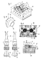
- FIGS. 5 and 7 the embedding of the housing 4 or of the plug connection part 3 in a lower mold half 14 of the injection molding tool 14, 15 can be seen.
- an unfinished connector part is shown with reference to Figure 5 in a cavity shown on the left in the drawing left, in which the housing 4 is already electrically connected to the harness 8, and in which on the housing 4 already the fixing nut is arranged.
- the protective coating is not yet applied.
- the right in the drawing right cavity shows the finished with the protective sheath 5 molded connector part 3.
- the upper mold half 15 is, as can also be seen with reference to Figures 6 and 7, provided at an upper vertex of the cavity with a groove-shaped recess parallel to Center longitudinal axis of the housing 4 is aligned and leads to the corresponding shape of the marking 7.
- the housing 4 is by means of a positioning part 16 aligned within the corresponding cavity of the tool half 14 that the coding 9 is aligned at the top vertex of the plug portion of the housing 4 and thus vertically above.
- the positioning member 16 is provided with a corresponding to the plug portion of the housing 4, cylindrical bushing portion 19 which is analogous to the mating housing 2 of the control box 1 with a radially inwardly facing profiling 20 is provided.
- the positioning member 16 is provided on the back with a web-like guide section 17 which can be inserted into a vertical guide groove 18 of the tool half 14.
- the profiling of the bushing section 19 of the positioning part 16 is provided exactly at the vertical upper vertex of the hollow cylindrical bushing section 19, so that with vertical insertion of the positioning member 16, the profiling 20 is always at the vertically upper vertex of the bushing portion 19. Inserting the plug-in portion of the housing 4 in the positioning member 16 thus inevitably causes a vertically upward positioning of the coding 9 of the housing 4 in an insertion of the positioning member 16 in the vertical guide groove 18 of the mold half.
- the protective jacket 5 is applied ,
- the corresponding orientation of the positioning part 16 and the coding 9 can be clearly seen again with reference to FIGS. 8 and 9.
- the defined orientation of the housing 4 ensures that the marking 7 is formed exactly in axial alignment with the coding 9.
- the marking 7 represents a web-like profiling, which extends starting from a front in the insertion direction annular collar of the protective sheath 5 in the axial alignment of the coding 9 over part of the axial length of the protective sheath 5 to the harness 8 towards the rear.
- the fixing nut 6 is insoluble, but still held rotatably on the housing 4.
- the fixing nut 6 has for this purpose at its back to Aufschraubraum Front end in basically known manner an annular flange on ( Figure 1), whose free inner diameter is smaller than the outer diameter of the annular shoulder 12 of the housing 4 ( Figure 4), but larger than the outer diameter of the guide portion 13.
- the fixing nut is rotatably on the one hand Guide portion 13 and the other over the axial length of the guide portion 13 and axially movable on the housing 4 held.
- the fixing nut 6 After insertion of the plug portion of the housing 4 in the mating housing 2 of the control box 1, the fixing nut 6 is screwed onto the external thread of the mating housing 2 and pulls over its radially inwardly projecting annular flange and the annular shoulder 12 of the housing 4, the housing 4 axially against the mating housing. 2 In this case, the elastic seal 11 is compressed, so that the connector is sealed watertight.
- the plug connection part 3 represents the contact plug-in unit in conjunction with the fixing nut 6.
- the contact plug-in unit in the sense of the invention is thus intended to denote the entire component without fixing nut, while the plug connection part 3 designates the contact plug-in unit including fixing nut 6.
- a fixing nut 6a is provided in the embodiment according to FIGS 11 to 13 instead of the permanently attached to the housing 4 fixing nut 6a, which after completion the entire contact plug-in unit can be applied to the front side of the housing 4.
- a fixing nut 6a shown in FIGS 11 to 13 is provided, which can be applied from the provided with the plug portion end face of the housing 4 forth on the contact plug-in unit of Figure 4.
- the fixing nut 6a applied to the housing 4 can be seen.
- the housing 4 is not yet connected to the harness 8 and also not yet provided with the protective sheath 5 for reasons of clarity.
- the fixing nut 6a is constructed in two parts. It has a cylindrical sleeve externally provided with profiles for facilitating manual engagement.
- the hollow cylindrical sleeve has a continuous over the entire length, cylindrical inner shell whose diameter is greater than the outer diameter of the annular shoulder 12 of the housing 4 ( Figure 4).
- In the hollow cylindrical sleeve of the fixing nut 6a are provided on diametrically opposite sides to the circumferential direction extending slots 23, which are designed as inwardly and outwardly open passages.
- the next to the hollow cylindrical sleeve second component of the fixing nut 6a is serving as a holding section in the context of the invention retaining clip 21, which is made of an at least slightly elastic material, in particular a spring steel or a plastic material.
- the retaining clip 21 has an annular strap portion which extends over a circumferential angle of more than 180 °, and preferably less than 270 °, in this case 230 °.
- radially inwardly projecting guide jaws 22 are provided, which are integrally connected to the bracket portion.
- the guide jaws 22 are curved radially inwardly cylinder-section-shaped, wherein a radius of curvature preferably about the radius of curvature of the cylindrical guide portion 13 of the housing 4 corresponds.
- the guide jaws 22 are matched in their circumferential length and in their thickness, ie in their axial length, to the dimensions of the slots 23 such that the guide jaws 22 can engage in the slots 23 in the slid state of the retaining clip 21 (FIG. 12). In this fixing state of the retaining clip 21, the guide jaws 22 sit with only a small clearance in the slots 23 in order to at least largely avoid tilting of the retaining clip 21 with respect to the hollow cylindrical sleeve of the fixing nut 6a.
- the insertion of the retaining clip 21 into the slots 23 takes place in a simple manner in that the retaining clip 21 is slightly elastically expanded during radial sliding onto the hollow cylindrical sleeve of the fixing nut 6a until the guide jaws 22 engage in the slots 23.
- the radius of the circular bracket portion of the retaining clip 21 corresponds approximately to the radius of curvature of the Au- ⁇ enmantels the hollow cylindrical sleeve of the fixing nut 6a, so that the retaining clip 21 is arranged in the snapped state almost free of stress. As a result, the permanent tension of the retaining clip 21 is reduced during operation of the connector part 3.
- the retaining clip 21 is radially attached to the hollow cylindrical sleeve of the fixing nut 6a until the guide jaws 22 engage in the slots 23.
- the now radially inwardly projecting guide jaws 22 cause the axial securing of the fixing nut 6a on the guide portion 13 of the housing 4.
- the support profiles 24, 25 as well as the vote of the guide jaws 22 on the dimensions of the slots 23 serve a reliable axial securing the fixing nut 6a when tightening on serving as a connecting element of the mating contact unit external thread on the housing 2 of the control box 1 to effect.
Landscapes
- Engineering & Computer Science (AREA)
- Manufacturing & Machinery (AREA)
- Details Of Connecting Devices For Male And Female Coupling (AREA)
- Manufacturing Of Electrical Connectors (AREA)
Applications Claiming Priority (1)
| Application Number | Priority Date | Filing Date | Title |
|---|---|---|---|
| DE200610052399 DE102006052399B4 (de) | 2006-10-31 | 2006-10-31 | Elektrisches Steckverbindungsteil |
Publications (2)
| Publication Number | Publication Date |
|---|---|
| EP1919039A2 true EP1919039A2 (fr) | 2008-05-07 |
| EP1919039A3 EP1919039A3 (fr) | 2009-07-01 |
Family
ID=39015995
Family Applications (1)
| Application Number | Title | Priority Date | Filing Date |
|---|---|---|---|
| EP07020878A Withdrawn EP1919039A3 (fr) | 2006-10-31 | 2007-10-25 | Elément de connexion électrique, son procédé de fabrication et outil de moulage par injection |
Country Status (2)
| Country | Link |
|---|---|
| EP (1) | EP1919039A3 (fr) |
| DE (1) | DE102006052399B4 (fr) |
Cited By (2)
| Publication number | Priority date | Publication date | Assignee | Title |
|---|---|---|---|---|
| CN102394440A (zh) * | 2011-09-05 | 2012-03-28 | 张家港友诚科技机电有限公司 | 充电接口的连接结构 |
| WO2025200839A1 (fr) * | 2024-03-25 | 2025-10-02 | 湖南省华芯医疗器械有限公司 | Ensemble enfichable et système d'endoscope |
Families Citing this family (1)
| Publication number | Priority date | Publication date | Assignee | Title |
|---|---|---|---|---|
| DE102016215686A1 (de) * | 2016-08-22 | 2018-02-22 | Lq Mechatronik-Systeme Gmbh | Steckverbinder mit angespritztem Isolierkörper und Verfahren zu seiner Herstellung |
Family Cites Families (7)
| Publication number | Priority date | Publication date | Assignee | Title |
|---|---|---|---|---|
| US2697211A (en) * | 1950-12-30 | 1954-12-14 | Pyle National Co | Multicontact connector and method of making same |
| US3994553A (en) * | 1974-01-09 | 1976-11-30 | Reynolds Industries, Inc. | Discharge resistant cable connector |
| US5453029A (en) * | 1994-08-31 | 1995-09-26 | Cooper Industries, Inc. | Contact support for a molded connector |
| US5641310A (en) * | 1994-12-08 | 1997-06-24 | Hubbell Incorporated | Locking type electrical connector with retention feature |
| JP3292462B2 (ja) * | 1998-05-29 | 2002-06-17 | ホシデン株式会社 | ロック機構付きコネクタ |
| US6475009B2 (en) * | 2000-06-02 | 2002-11-05 | The Siemon Company | Industrial telecommunications connector |
| US6585533B1 (en) * | 2002-08-28 | 2003-07-01 | Woodhead Industries, Inc. | Vibration resistant electrical connector |
-
2006
- 2006-10-31 DE DE200610052399 patent/DE102006052399B4/de active Active
-
2007
- 2007-10-25 EP EP07020878A patent/EP1919039A3/fr not_active Withdrawn
Cited By (2)
| Publication number | Priority date | Publication date | Assignee | Title |
|---|---|---|---|---|
| CN102394440A (zh) * | 2011-09-05 | 2012-03-28 | 张家港友诚科技机电有限公司 | 充电接口的连接结构 |
| WO2025200839A1 (fr) * | 2024-03-25 | 2025-10-02 | 湖南省华芯医疗器械有限公司 | Ensemble enfichable et système d'endoscope |
Also Published As
| Publication number | Publication date |
|---|---|
| EP1919039A3 (fr) | 2009-07-01 |
| DE102006052399B4 (de) | 2008-10-30 |
| DE102006052399A1 (de) | 2008-05-08 |
Similar Documents
| Publication | Publication Date | Title |
|---|---|---|
| EP2220419B1 (fr) | Conduit chauffable pour fluides | |
| EP2311154B1 (fr) | Câble de données | |
| EP3132506B1 (fr) | Embout de câble | |
| EP2617104A1 (fr) | Contact électrique | |
| EP1070642A2 (fr) | Dispositif de chauffage pour lave-glace | |
| DE102018210892B4 (de) | Steckverbindungselement für ein Kraftfahrzeug und Verfahren zum Herstellen eines solchen Steckverbindungselements | |
| DE10350763A1 (de) | Koaxialkabel mit Winkelsteckverbindung | |
| DE102015004750B4 (de) | Verbinder mit Durchgangstülle und Verfahren zum Herstellen desselben | |
| EP2532061B1 (fr) | Appareil électrique pourvu d'un passage pour un câble à travers une paroi de boîtier | |
| EP0533729A1 (fr) | Dispositif de decharge de traction de cable. | |
| EP2742284B1 (fr) | Dispositif électrique pourvu d'un élément d'étanchéité, élément d'étanchéité pour un dispositif électrique et procédé pour rendre étanche un boîtier | |
| DE29806645U1 (de) | Kabelsteckverbinder | |
| EP1919039A2 (fr) | Elément de connexion électrique, son procédé de fabrication et outil de moulage par injection | |
| WO2008037710A1 (fr) | Machine électrique, notamment moteur électrique, munie d'un câble de raccordement serti du côté de la machine | |
| EP0444478A1 (fr) | Porte-contact pour prise de courant ou connecteur pour le raccordement de remorques de véhicules | |
| DE102010030958A1 (de) | Anordnung, insbesondere Stecker und Verfahren zur Herstellung | |
| DE102017004266A1 (de) | Steckverbinder, Stecker und Steckverbindersystem | |
| DE60000425T2 (de) | Steckverbinder für die elektrische Verbindung zwischen einem Fahrzeug und Anhänger | |
| DE102011085649A1 (de) | Hydraulisches System | |
| DE102014109270B4 (de) | Leitungsfixierung, Stecker mit einer Leitungsfixierung und Verfahren zum Fixieren einer elektrischen Leitung an einem Stecker | |
| EP0676831B1 (fr) | Connecteur, notamment pour la connexion électrique des remorques | |
| DE202006019836U1 (de) | Elektrisches Steckverbindungsteil und Spritzgusswerkzeug | |
| DE202010015157U1 (de) | Elektromechanische Steckvorrichtung | |
| EP0709252B1 (fr) | Faisceau de câbles en particulier pour le montage dans une carosserie de voiture | |
| EP0374592A2 (fr) | Prise de courant pour une connexion multipolaire d'un raccordement électrique de remorque, ainsi qu'un faisceau de câbles multipolaire pour monter dans une telle prise de courant |
Legal Events
| Date | Code | Title | Description |
|---|---|---|---|
| PUAI | Public reference made under article 153(3) epc to a published international application that has entered the european phase |
Free format text: ORIGINAL CODE: 0009012 |
|
| AK | Designated contracting states |
Kind code of ref document: A2 Designated state(s): AT BE BG CH CY CZ DE DK EE ES FI FR GB GR HU IE IS IT LI LT LU LV MC MT NL PL PT RO SE SI SK TR |
|
| AX | Request for extension of the european patent |
Extension state: AL BA HR MK RS |
|
| PUAL | Search report despatched |
Free format text: ORIGINAL CODE: 0009013 |
|
| AK | Designated contracting states |
Kind code of ref document: A3 Designated state(s): AT BE BG CH CY CZ DE DK EE ES FI FR GB GR HU IE IS IT LI LT LU LV MC MT NL PL PT RO SE SI SK TR |
|
| AX | Request for extension of the european patent |
Extension state: AL BA HR MK RS |
|
| AKX | Designation fees paid | ||
| STAA | Information on the status of an ep patent application or granted ep patent |
Free format text: STATUS: THE APPLICATION IS DEEMED TO BE WITHDRAWN |
|
| 18D | Application deemed to be withdrawn |
Effective date: 20100105 |
|
| REG | Reference to a national code |
Ref country code: DE Ref legal event code: 8566 |