EP1919048B1 - Vorrichtung zur Behandlung der Korona - Google Patents
Vorrichtung zur Behandlung der Korona Download PDFInfo
- Publication number
- EP1919048B1 EP1919048B1 EP07020765A EP07020765A EP1919048B1 EP 1919048 B1 EP1919048 B1 EP 1919048B1 EP 07020765 A EP07020765 A EP 07020765A EP 07020765 A EP07020765 A EP 07020765A EP 1919048 B1 EP1919048 B1 EP 1919048B1
- Authority
- EP
- European Patent Office
- Prior art keywords
- electrode
- substrate
- electrodes
- active
- counter electrode
- Prior art date
- Legal status (The legal status is an assumption and is not a legal conclusion. Google has not performed a legal analysis and makes no representation as to the accuracy of the status listed.)
- Not-in-force
Links
- 238000003851 corona treatment Methods 0.000 title claims description 8
- 239000000758 substrate Substances 0.000 claims abstract description 50
- 239000011810 insulating material Substances 0.000 claims abstract description 6
- 230000005611 electricity Effects 0.000 claims abstract description 5
- 239000004020 conductor Substances 0.000 claims description 14
- 229910052751 metal Inorganic materials 0.000 claims description 6
- 239000002184 metal Substances 0.000 claims description 6
- 229910052709 silver Inorganic materials 0.000 claims description 3
- 239000004332 silver Substances 0.000 claims description 3
- 229910010293 ceramic material Inorganic materials 0.000 claims 1
- 230000000694 effects Effects 0.000 abstract description 10
- 238000000034 method Methods 0.000 abstract description 9
- 239000010410 layer Substances 0.000 description 11
- 239000000919 ceramic Substances 0.000 description 7
- 239000000463 material Substances 0.000 description 6
- 239000004033 plastic Substances 0.000 description 5
- 229920003023 plastic Polymers 0.000 description 5
- -1 stickers Substances 0.000 description 4
- 239000004698 Polyethylene Substances 0.000 description 2
- 239000004411 aluminium Substances 0.000 description 2
- 229910052782 aluminium Inorganic materials 0.000 description 2
- XAGFODPZIPBFFR-UHFFFAOYSA-N aluminium Chemical compound [Al] XAGFODPZIPBFFR-UHFFFAOYSA-N 0.000 description 2
- 239000000976 ink Substances 0.000 description 2
- 239000012212 insulator Substances 0.000 description 2
- 238000004519 manufacturing process Methods 0.000 description 2
- 229920000573 polyethylene Polymers 0.000 description 2
- 239000004743 Polypropylene Substances 0.000 description 1
- 239000011247 coating layer Substances 0.000 description 1
- 238000000576 coating method Methods 0.000 description 1
- 230000008878 coupling Effects 0.000 description 1
- 238000010168 coupling process Methods 0.000 description 1
- 238000005859 coupling reaction Methods 0.000 description 1
- 239000003989 dielectric material Substances 0.000 description 1
- 238000001125 extrusion Methods 0.000 description 1
- 238000007641 inkjet printing Methods 0.000 description 1
- 238000009413 insulation Methods 0.000 description 1
- 239000004922 lacquer Substances 0.000 description 1
- 239000012811 non-conductive material Substances 0.000 description 1
- 239000000123 paper Substances 0.000 description 1
- 229920006267 polyester film Polymers 0.000 description 1
- 229920001155 polypropylene Polymers 0.000 description 1
- 229920000915 polyvinyl chloride Polymers 0.000 description 1
- 239000004800 polyvinyl chloride Substances 0.000 description 1
- 238000007639 printing Methods 0.000 description 1
- 230000001681 protective effect Effects 0.000 description 1
- 229910052710 silicon Inorganic materials 0.000 description 1
- 239000010703 silicon Substances 0.000 description 1
Images

Classifications
-
- H—ELECTRICITY
- H01—ELECTRIC ELEMENTS
- H01T—SPARK GAPS; OVERVOLTAGE ARRESTERS USING SPARK GAPS; SPARKING PLUGS; CORONA DEVICES; GENERATING IONS TO BE INTRODUCED INTO NON-ENCLOSED GASES
- H01T19/00—Devices providing for corona discharge
Definitions
- the invention relates to the corona treatment technique.
- the corona treatment basically consists in applying an high intensity electric discharge to the surface of a certain substrate, in order to increase the active tension and consequently to improve the fixing power of printing inks, stickers or coatings.
- the substrate can be either a film or an extruded item, sheets or plates, wires, tubes, metal plates etc.
- the corona treatment is widely used to increase the wettability of plastic, metal or paper films, and to help the adhesion of inks, stickers, lacquers... ; it is often used for polyethylene, polypropylene, PVC or polyester films, but it is suitable for almost any plastic material and also for some non-plastic materials such as paper and aluminium.
- a corona treater basically comprises a high frequency generator, a step-up transformer connected with one or more metal electrodes, and a roll (or a sheet) electrically connected to the ground and acting as a counter electrode. Said roll can be coated with insulating material (silicon, ceramic or others).
- the substrate is inserted between the electrodes and the roll, with known dragging means. This way, the surface of the substrate is activated by the electric discharge generated between the electrodes in tension and the roll connected to the ground.
- Machines can be devised to work on their own or connected to another unit, for example an extruder, a flexo printer, a rotogravure, a coupling machines, a sheets production line, etc.
- the substrate comprises a sheet or an extruded 10 mm thick; the air gap should be 1,5 mm, and the dielectric roll covering is usually 3 mm thick.
- the total distance between the electrodes and the conductive part of the roll is more or less 15 mm, and considering an average dielectric rigidity of a substrate of 2.000 V/mm, the resulting trigger tension is equal to 30.000 V. So high tensions can be a problem for safety and can damage and/or burn some materials. Moreover, such tensions require a proper design of the insulation and protection means of the device, which cause overall dimensions of the machine.
- the surface to treat is basically a narrow band along the external surface of the tube, and so the prior art turns out to be not really suitable.
- the corona treatment device disclosed in EP-A-1047165 is of the type wherein the active electrode is arranged opposite the counter-electrode, said active electrode including high voltage conductor in the portion facing said counter electrode.
- the object of the invention is to overcome all these problems.
- the scope of the invention is to reduce the tension necessary for the trigger of the discharge and to direct it towards the substrate, without the use of a forced air flow even if the electrode and the counter electrode are one beside the other, as in the prior art.
- a further aim of the invention is to treat more easily the sides of tubes or other curved surfaces, as well as complex three-dimensional objects surfaces.
- the inner volume created by the tubular body is not filled with conductive material, since the only conductive part is said internal coating layer. Typically, the interior is filled with air.
- the invention enable to avoid the use of rolls or plates connected to the ground, due to the fact that the electrodes are placed on the same side of the substrate (i.e. next to it, or over it), and to the fact that the electric discharge is produced directly between the active and passive electrode/s.
- the discharge does not have to pass through neither the whole layer of the substrate, nor the insulating layer of the roll. It follows that the trigging tension required is much lower than with the method in which electrode and counter electrode are on opposite parts of the substrate, with the same effect.
- the described structure of the electrode with hollow interior and lined with conductive material only in the inner part near the substrate produces an arch discharge projecting towards the substrate instead of concentrating in the space between the sides of the electrodes, as in the known systems shown in Fig. 1 e) .
- the invention relates to a method for the corona effect treatment on a surface S, or part of it, of a substrate, such as an extruded, a tube or a sheet of material.
- the treatment is the effect of the electric discharge E generated between at least an active electrode 10 and a corresponding passive electrode (or counter electrode) 11, which are placed one beside the other and on the same part, with respect to the substrate, i.e. over it or near it.
- the active electrode 10, as shown in the scheme, has a connection AT to a generator and possibly to a tension raiser transformer; the passive electrode 11 has an ground connection G.
- Active electrode 10 comprises a ceramic bar or tube with hallow interior and a side 12 towards substrate S, lined with a conductive layer 14 connected to high tension AT.
- Said conductive layer is preferably made of metal or even more preferably of silver.
- the counter electrode or passive electrode 11 has the same structure as electrode 10, with a face 13 likewise towards substrate S and lined with a conductive layer 14.
- Internal volume 15 of the electrode 10 is filled with air; internal volume 16 of the counter electrode 11 is likewise filled with air.
- Electric discharge E is generated between the metallic side 12 of the active electrode 10 and the metallic side 13, placed next to it, of the counter electrode 11, hitting surface S of the substrate.
- the electric discharge E tends to produce an arch projecting towards the underlying surface S of the substrate, instead of generating useless sparks between the sides of the electrodes as it could happen, for example, if there were any conductive material in interiors 15 and 16 of the electrodes.
- the method provided by the invention enables a strict control of the discharges and, thanks to the proper placing of the electrodes with respect to the plane on which the substrate slides, allows to direct electricity towards the substrate to treat instead of dispersing it in spaces useless for the corona treatment, such as the sides of the electrodes.
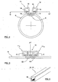
- Fig. 2 shows the position of electrodes 10 and 11 to treat the side of a tube: electrodes 10 and 11 are placed next to the tube and immediately close to its external surface S, preferably with sides 12 and 13 perpendicular to the radial direction defined by the tube.
- electrodes are in odd number, the external ones are connected to the ground. Thanks to this, the protective casing of the machine can be placed closer to the external electrodes, since these ones are not in tension (i.e. live).
- Fig. 3 discloses an active electrode 10 and two external electrodes connected to the ground 11A, 11 B.
- each active electrode discharges towards at least one passive electrode.
- a reversed disposition can be used, instead of that shown in Fig. 3 , with the passive electrode in the middle and two active electrodes on the sides.
- the electrodes disposition in Fig. 3 is suitable to treat surfaces of plane sheets, extruded or plates or the like, which are carried continuously and by known means, sliding underneath the electrodes.
- the treatment can be equally carried out with a steady substrate and a mobile electrode moved to treat the whole required surface. More in detail, another version (not showed) implies the connection of the active and passive electrodes to a manual or automatic moving system (mobile electrodes), to work on a steady substrate or even on plane surfaces of three-dimensional objects.
- the treatment of objects' surfaces, as known, is possible if said surfaces are physically reachable by the electrodes, considering the electrodes' dimensions and shapes and the limited corona discharge action field (usually 2-3 mm).
- Fig. 4 shows the preferred shape of the electrode, referring indifferently to an active or a passive electrode, having face 12 or 13, towards the substrate, coated inside with an electricity conductive layer (14).
- electrodes can have a transversal section different from the basically square section of Figs. 2-4 .
- the electrodes can have a trapezoidal section, preferably with the smaller side facing the substrate, or a polygonal section, having one or more internal sides lined with conductive material, or even a circular section, part of which is lined with conductive material.
- the insulating material of the electrodes can be different from the mentioned ceramic; and the conductive material of the covering layer 14 can be different from the mentioned silver. Said materials being described as preferred.
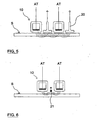
- Fig. 5 shows a scheme with counter electrode 20 composed by a metallic T beam
- Fig. 6 shows an even cheaper version in which the counter electrode is simply a metal wire 21 connected to the ground.
- the invention is suitable for treating both plastic and non-plastic materials, such as paper and aluminium, and can be used with known types of devices for corona treatment.
Landscapes
- Physics & Mathematics (AREA)
- Engineering & Computer Science (AREA)
- Plasma & Fusion (AREA)
- Physical Or Chemical Processes And Apparatus (AREA)
- Treatments Of Macromolecular Shaped Articles (AREA)
Claims (12)
- Vorrichtung zur Coronabehandlung eines Substrates (S), umfassend mindestens eine aktive Elektrode (10) und mindestens eine Gegenelektrode (11, 20, 21), die neben besagter aktiven Elektrode (10) positioniert und mit der Erde verbunden ist,- wobei besagte aktive und Gegenelektroden an der gleichen Seite in Bezug auf besagtes Substrat (S) positioniert sind, dadurch gekennzeichnet, dass- besagte aktive Elektrode (10) durch einen Hohlkörper gebildet wird, der im Wesentlichen eine röhrenförmig verlängerte Form aufweist und aus Isoliermaterial besteht,- die Seitenfläche (12) der dem Substrat (S) zugewandten besagten aktiven Elektrode (10) innen mit einer elektrizitätsleitenden Schicht (14) beschichtet ist,- die verbleibenden Seitenflächen der besagten aktiven Elektrode (10) kein leitfähiges Material aufweisen.
- Vorrichtung gemäß Anspruch 1, dadurch gekennzeichnet, dass besagte Gegenelektrode (20, 21) aus elektrisch leitfähigem Material besteht.
- Vorrichtung gemäß Anspruch 1, dadurch gekennzeichnet, dass besagte Gegenelektrode (11) aus einem Hohlkörper gebildet wird, der im Wesentlichen eine röhrenförmig verlängerte Form aufweist und aus Isoliermaterial besteht, wobei die Seitenfläche (13) der dem Substrat (S) zugewandten besagten Gegenelektrode(11) innen mit einer elektrizitätsleitenden Schicht (14) beschichtet ist und die verbleibenden Seitenflächen der besagten Gegenelektrode (11) kein leitfähiges Material aufweisen.
- Vorrichtung gemäß Anspruch 3, dadurch gekennzeichnet, dass besagte hohle Elektrode (10, 11) aus Keramik besteht.
- Vorrichtung gemäß Anspruch 4, dadurch gekennzeichnet, dass besagte leitende Schicht (14) aus Metall besteht.
- Vorrichtung gemäß Anspruch 5, dadurch gekennzeichnet, dass besagte leitende Schicht (14) aus Silber besteht.
- Vorrichtung gemäß Anspruch 1 oder 3, dadurch gekennzeichnet, dass besagte hohle Elektrode (10, 11) einen Stab mit polygonalem Querschnitt umfasst, wobei besagter Querschnitt eine dem Substrat (S) zugewandte Seite (12, 13) aufweist und mit besagter leitenden Schicht (14) gefluchtet ist.
- Vorrichtung gemäß Anspruch 7, dadurch gekennzeichnet, dass der Elektrodenstab einen quadratischen oder trapezförmigen Querschnitt aufweist, dessen kleinere Seite dem Substrat zugewandt ist.
- Vorrichtung gemäß einem jeden der vorhergehenden Ansprüche, dadurch gekennzeichnet, dass viele aktive Elektroden (10) und passive Elektroden (11, 20, 21) eingeplant sind.
- Vorrichtung gemäß Anspruch 9, dadurch gekennzeichnet, dass sich besagte Elektroden nebeneinander und abwechselnd auf der gleichen Fläche befinden, so dass viele elektrische Entladungen zwischen jeder aktiven Elektrode (10) und mindestens einer passiven Elektrode zur Behandlung von ebenen Folien, Extrudiertem, Platten und Ähnlichem erzeugt werden können.
- Vorrichtung gemäß Anspruch 10, dadurch gekennzeichnet, dass die Elektroden in ungerader Anzahl vorhanden sind und die beiden Außenelektroden (11A, 11B) passiv sind, das heißt mit der Erde verbunden.
- Vorrichtung gemäß einem jeden der vorhergehenden Ansprüche, dadurch gekennzeichnet, dass die Elektroden mit einem manuellen oder automatischen beweglichen System zur Behandlung eines festen Substrates oder ebener Flächen von Gegenständen verbunden sind.
Applications Claiming Priority (1)
| Application Number | Priority Date | Filing Date | Title |
|---|---|---|---|
| IT000022A ITCR20060022A1 (it) | 2006-11-03 | 2006-11-03 | Metodo e apparecchio per trattamento corona |
Publications (2)
| Publication Number | Publication Date |
|---|---|
| EP1919048A1 EP1919048A1 (de) | 2008-05-07 |
| EP1919048B1 true EP1919048B1 (de) | 2011-06-08 |
Family
ID=38973637
Family Applications (1)
| Application Number | Title | Priority Date | Filing Date |
|---|---|---|---|
| EP07020765A Not-in-force EP1919048B1 (de) | 2006-11-03 | 2007-10-24 | Vorrichtung zur Behandlung der Korona |
Country Status (3)
| Country | Link |
|---|---|
| EP (1) | EP1919048B1 (de) |
| AT (1) | ATE512491T1 (de) |
| IT (1) | ITCR20060022A1 (de) |
Families Citing this family (2)
| Publication number | Priority date | Publication date | Assignee | Title |
|---|---|---|---|---|
| EP2866318A1 (de) | 2013-10-24 | 2015-04-29 | OCE-Technologies B.V. | Elektrode zur Behandlung eines Substrat mit dielektrischer Barriereentladung |
| EP3344458B1 (de) * | 2015-09-01 | 2019-06-12 | OCE-Technologies B.V. | Plasmabehandlungssystem für geschnittene blattmedien |
Family Cites Families (2)
| Publication number | Priority date | Publication date | Assignee | Title |
|---|---|---|---|---|
| GB1100414A (en) * | 1964-05-19 | 1968-01-24 | Ici Ltd | Treatment of plastics surfaces with an electrical discharge to improve their bonding properties |
| EP1047165B1 (de) * | 1999-04-21 | 2002-03-13 | Softal Electronic Erik Blumenfeld Gmbh & Co. | Barrierenelektrode zur Oberflächenbehandlung von elektrisch leitenden oder nichtleitenden Materialien sowie Anordnung derartiger Barrierenelektroden |
-
2006
- 2006-11-03 IT IT000022A patent/ITCR20060022A1/it unknown
-
2007
- 2007-10-24 AT AT07020765T patent/ATE512491T1/de not_active IP Right Cessation
- 2007-10-24 EP EP07020765A patent/EP1919048B1/de not_active Not-in-force
Also Published As
| Publication number | Publication date |
|---|---|
| ITCR20060022A1 (it) | 2008-05-04 |
| EP1919048A1 (de) | 2008-05-07 |
| ATE512491T1 (de) | 2011-06-15 |
Similar Documents
| Publication | Publication Date | Title |
|---|---|---|
| US3483374A (en) | Apparatus for the surface treatment of workpieces by electrical discharges | |
| CA1131164A (en) | Method and apparatus for the corona discharge treatment of webs, and webs treated therewith | |
| US5731948A (en) | High energy density capacitor | |
| US20100112235A1 (en) | Method for treating plasma under continuous atmospheric pressure of work pieces, in particular, material plates or strips | |
| US6998574B2 (en) | Welding torch with plasma assist | |
| US8411406B2 (en) | Electrical ionizer and methods of making and using | |
| CN104903045A (zh) | 用于在透明衬底相对两侧上的涂层内形成图案的方法和装置 | |
| US20110181998A1 (en) | Deposited film and film capacitor using the same | |
| WO2006043420A1 (ja) | プラズマ生成装置 | |
| EP1919048A1 (de) | Verfahren und Vorrichtung zur Behandlung der Korona | |
| ITMI960248A1 (it) | Film dielettrico metallizzato a resistenza variabile e relativo condensatore | |
| US4777338A (en) | Perforation of synthetic plastic films | |
| US20110223357A1 (en) | Surface treatment method | |
| US3133193A (en) | Corona discharge apparatus for the surface treatment of plastic resins | |
| US20070151748A1 (en) | Flexible carrier with an electrically conducting structure | |
| US5401368A (en) | Fluid-cooled hollow copper electrodes and their use in corona or ozone applications | |
| JP5552337B2 (ja) | イオン発生装置 | |
| JP2001006844A (ja) | 導電性又は非導電性の材料の表面処理のためのバリヤ電極並びにこのようなバリヤ電極を有する装置 | |
| US10164165B2 (en) | Piezoelectric transformer and counter electrode | |
| EP3470367B1 (de) | Ozongenerator | |
| JP2008230826A (ja) | シートロール体の製造装置および製造方法 | |
| EP2951846B1 (de) | Metallisiertefolienkondensator mit wärmeleitenderfolie und wärmeleitenderfolie für elektrische leistungskomponente | |
| JP5668134B2 (ja) | イオン風発生体及びイオン風発生装置 | |
| CZ31880U1 (cs) | Zařízení pro vytvoření dielektrického bariérového výboje | |
| DE102015101804B4 (de) | Blitzlampenanordnung mit kapazitiver Kopplung zwischen Zündelektrode und Zündelektroden-Zuleitung bzw. entsprechende Blitzlampen-Lageranordnung |
Legal Events
| Date | Code | Title | Description |
|---|---|---|---|
| PUAI | Public reference made under article 153(3) epc to a published international application that has entered the european phase |
Free format text: ORIGINAL CODE: 0009012 |
|
| AK | Designated contracting states |
Kind code of ref document: A1 Designated state(s): AT BE BG CH CY CZ DE DK EE ES FI FR GB GR HU IE IS IT LI LT LU LV MC MT NL PL PT RO SE SI SK TR |
|
| AX | Request for extension of the european patent |
Extension state: AL BA HR MK RS |
|
| 17P | Request for examination filed |
Effective date: 20081030 |
|
| AKX | Designation fees paid |
Designated state(s): AT BE BG CH CY CZ DE DK EE ES FI FR GB GR HU IE IS IT LI LT LU LV MC MT NL PL PT RO SE SI SK TR |
|
| 17Q | First examination report despatched |
Effective date: 20090216 |
|
| GRAP | Despatch of communication of intention to grant a patent |
Free format text: ORIGINAL CODE: EPIDOSNIGR1 |
|
| RTI1 | Title (correction) |
Free format text: CORONA TREATMENT DEVICE |
|
| GRAS | Grant fee paid |
Free format text: ORIGINAL CODE: EPIDOSNIGR3 |
|
| GRAA | (expected) grant |
Free format text: ORIGINAL CODE: 0009210 |
|
| AK | Designated contracting states |
Kind code of ref document: B1 Designated state(s): AT BE BG CH CY CZ DE DK EE ES FI FR GB GR HU IE IS IT LI LT LU LV MC MT NL PL PT RO SE SI SK TR |
|
| REG | Reference to a national code |
Ref country code: GB Ref legal event code: FG4D |
|
| REG | Reference to a national code |
Ref country code: CH Ref legal event code: EP |
|
| REG | Reference to a national code |
Ref country code: IE Ref legal event code: FG4D |
|
| REG | Reference to a national code |
Ref country code: DE Ref legal event code: R096 Ref document number: 602007015034 Country of ref document: DE Effective date: 20110721 |
|
| REG | Reference to a national code |
Ref country code: NL Ref legal event code: VDEP Effective date: 20110608 |
|
| PG25 | Lapsed in a contracting state [announced via postgrant information from national office to epo] |
Ref country code: LT Free format text: LAPSE BECAUSE OF FAILURE TO SUBMIT A TRANSLATION OF THE DESCRIPTION OR TO PAY THE FEE WITHIN THE PRESCRIBED TIME-LIMIT Effective date: 20110608 Ref country code: SE Free format text: LAPSE BECAUSE OF FAILURE TO SUBMIT A TRANSLATION OF THE DESCRIPTION OR TO PAY THE FEE WITHIN THE PRESCRIBED TIME-LIMIT Effective date: 20110608 |
|
| PG25 | Lapsed in a contracting state [announced via postgrant information from national office to epo] |
Ref country code: CY Free format text: LAPSE BECAUSE OF FAILURE TO SUBMIT A TRANSLATION OF THE DESCRIPTION OR TO PAY THE FEE WITHIN THE PRESCRIBED TIME-LIMIT Effective date: 20110608 Ref country code: AT Free format text: LAPSE BECAUSE OF FAILURE TO SUBMIT A TRANSLATION OF THE DESCRIPTION OR TO PAY THE FEE WITHIN THE PRESCRIBED TIME-LIMIT Effective date: 20110608 Ref country code: GR Free format text: LAPSE BECAUSE OF FAILURE TO SUBMIT A TRANSLATION OF THE DESCRIPTION OR TO PAY THE FEE WITHIN THE PRESCRIBED TIME-LIMIT Effective date: 20110909 Ref country code: ES Free format text: LAPSE BECAUSE OF FAILURE TO SUBMIT A TRANSLATION OF THE DESCRIPTION OR TO PAY THE FEE WITHIN THE PRESCRIBED TIME-LIMIT Effective date: 20110919 Ref country code: SI Free format text: LAPSE BECAUSE OF FAILURE TO SUBMIT A TRANSLATION OF THE DESCRIPTION OR TO PAY THE FEE WITHIN THE PRESCRIBED TIME-LIMIT Effective date: 20110608 Ref country code: LV Free format text: LAPSE BECAUSE OF FAILURE TO SUBMIT A TRANSLATION OF THE DESCRIPTION OR TO PAY THE FEE WITHIN THE PRESCRIBED TIME-LIMIT Effective date: 20110608 Ref country code: FI Free format text: LAPSE BECAUSE OF FAILURE TO SUBMIT A TRANSLATION OF THE DESCRIPTION OR TO PAY THE FEE WITHIN THE PRESCRIBED TIME-LIMIT Effective date: 20110608 |
|
| PG25 | Lapsed in a contracting state [announced via postgrant information from national office to epo] |
Ref country code: NL Free format text: LAPSE BECAUSE OF FAILURE TO SUBMIT A TRANSLATION OF THE DESCRIPTION OR TO PAY THE FEE WITHIN THE PRESCRIBED TIME-LIMIT Effective date: 20110608 Ref country code: BE Free format text: LAPSE BECAUSE OF FAILURE TO SUBMIT A TRANSLATION OF THE DESCRIPTION OR TO PAY THE FEE WITHIN THE PRESCRIBED TIME-LIMIT Effective date: 20110608 |
|
| PG25 | Lapsed in a contracting state [announced via postgrant information from national office to epo] |
Ref country code: IS Free format text: LAPSE BECAUSE OF FAILURE TO SUBMIT A TRANSLATION OF THE DESCRIPTION OR TO PAY THE FEE WITHIN THE PRESCRIBED TIME-LIMIT Effective date: 20111008 Ref country code: EE Free format text: LAPSE BECAUSE OF FAILURE TO SUBMIT A TRANSLATION OF THE DESCRIPTION OR TO PAY THE FEE WITHIN THE PRESCRIBED TIME-LIMIT Effective date: 20110608 Ref country code: CZ Free format text: LAPSE BECAUSE OF FAILURE TO SUBMIT A TRANSLATION OF THE DESCRIPTION OR TO PAY THE FEE WITHIN THE PRESCRIBED TIME-LIMIT Effective date: 20110608 Ref country code: PT Free format text: LAPSE BECAUSE OF FAILURE TO SUBMIT A TRANSLATION OF THE DESCRIPTION OR TO PAY THE FEE WITHIN THE PRESCRIBED TIME-LIMIT Effective date: 20111010 |
|
| PG25 | Lapsed in a contracting state [announced via postgrant information from national office to epo] |
Ref country code: RO Free format text: LAPSE BECAUSE OF FAILURE TO SUBMIT A TRANSLATION OF THE DESCRIPTION OR TO PAY THE FEE WITHIN THE PRESCRIBED TIME-LIMIT Effective date: 20110608 Ref country code: PL Free format text: LAPSE BECAUSE OF FAILURE TO SUBMIT A TRANSLATION OF THE DESCRIPTION OR TO PAY THE FEE WITHIN THE PRESCRIBED TIME-LIMIT Effective date: 20110608 Ref country code: SK Free format text: LAPSE BECAUSE OF FAILURE TO SUBMIT A TRANSLATION OF THE DESCRIPTION OR TO PAY THE FEE WITHIN THE PRESCRIBED TIME-LIMIT Effective date: 20110608 |
|
| PLBE | No opposition filed within time limit |
Free format text: ORIGINAL CODE: 0009261 |
|
| STAA | Information on the status of an ep patent application or granted ep patent |
Free format text: STATUS: NO OPPOSITION FILED WITHIN TIME LIMIT |
|
| 26N | No opposition filed |
Effective date: 20120309 |
|
| PG25 | Lapsed in a contracting state [announced via postgrant information from national office to epo] |
Ref country code: IT Free format text: LAPSE BECAUSE OF FAILURE TO SUBMIT A TRANSLATION OF THE DESCRIPTION OR TO PAY THE FEE WITHIN THE PRESCRIBED TIME-LIMIT Effective date: 20110608 Ref country code: MC Free format text: LAPSE BECAUSE OF NON-PAYMENT OF DUE FEES Effective date: 20111031 |
|
| REG | Reference to a national code |
Ref country code: CH Ref legal event code: PL |
|
| GBPC | Gb: european patent ceased through non-payment of renewal fee |
Effective date: 20111024 |
|
| PG25 | Lapsed in a contracting state [announced via postgrant information from national office to epo] |
Ref country code: DK Free format text: LAPSE BECAUSE OF FAILURE TO SUBMIT A TRANSLATION OF THE DESCRIPTION OR TO PAY THE FEE WITHIN THE PRESCRIBED TIME-LIMIT Effective date: 20110608 |
|
| REG | Reference to a national code |
Ref country code: DE Ref legal event code: R097 Ref document number: 602007015034 Country of ref document: DE Effective date: 20120309 |
|
| REG | Reference to a national code |
Ref country code: FR Ref legal event code: ST Effective date: 20120629 |
|
| PG25 | Lapsed in a contracting state [announced via postgrant information from national office to epo] |
Ref country code: CH Free format text: LAPSE BECAUSE OF NON-PAYMENT OF DUE FEES Effective date: 20111031 Ref country code: LI Free format text: LAPSE BECAUSE OF NON-PAYMENT OF DUE FEES Effective date: 20111031 |
|
| REG | Reference to a national code |
Ref country code: IE Ref legal event code: MM4A |
|
| PG25 | Lapsed in a contracting state [announced via postgrant information from national office to epo] |
Ref country code: GB Free format text: LAPSE BECAUSE OF NON-PAYMENT OF DUE FEES Effective date: 20111024 Ref country code: FR Free format text: LAPSE BECAUSE OF NON-PAYMENT OF DUE FEES Effective date: 20111102 |
|
| PG25 | Lapsed in a contracting state [announced via postgrant information from national office to epo] |
Ref country code: IE Free format text: LAPSE BECAUSE OF NON-PAYMENT OF DUE FEES Effective date: 20111024 |
|
| PG25 | Lapsed in a contracting state [announced via postgrant information from national office to epo] |
Ref country code: MT Free format text: LAPSE BECAUSE OF FAILURE TO SUBMIT A TRANSLATION OF THE DESCRIPTION OR TO PAY THE FEE WITHIN THE PRESCRIBED TIME-LIMIT Effective date: 20110608 |
|
| PG25 | Lapsed in a contracting state [announced via postgrant information from national office to epo] |
Ref country code: LU Free format text: LAPSE BECAUSE OF NON-PAYMENT OF DUE FEES Effective date: 20111024 |
|
| PG25 | Lapsed in a contracting state [announced via postgrant information from national office to epo] |
Ref country code: BG Free format text: LAPSE BECAUSE OF FAILURE TO SUBMIT A TRANSLATION OF THE DESCRIPTION OR TO PAY THE FEE WITHIN THE PRESCRIBED TIME-LIMIT Effective date: 20110908 |
|
| PG25 | Lapsed in a contracting state [announced via postgrant information from national office to epo] |
Ref country code: TR Free format text: LAPSE BECAUSE OF FAILURE TO SUBMIT A TRANSLATION OF THE DESCRIPTION OR TO PAY THE FEE WITHIN THE PRESCRIBED TIME-LIMIT Effective date: 20110608 |
|
| PG25 | Lapsed in a contracting state [announced via postgrant information from national office to epo] |
Ref country code: HU Free format text: LAPSE BECAUSE OF FAILURE TO SUBMIT A TRANSLATION OF THE DESCRIPTION OR TO PAY THE FEE WITHIN THE PRESCRIBED TIME-LIMIT Effective date: 20110608 |
|
| PGFP | Annual fee paid to national office [announced via postgrant information from national office to epo] |
Ref country code: DE Payment date: 20141029 Year of fee payment: 8 |
|
| REG | Reference to a national code |
Ref country code: DE Ref legal event code: R119 Ref document number: 602007015034 Country of ref document: DE |
|
| PG25 | Lapsed in a contracting state [announced via postgrant information from national office to epo] |
Ref country code: DE Free format text: LAPSE BECAUSE OF NON-PAYMENT OF DUE FEES Effective date: 20160503 |