EP1919060B1 - Système de gestion de batterie et son procédé de commande - Google Patents
Système de gestion de batterie et son procédé de commande Download PDFInfo
- Publication number
- EP1919060B1 EP1919060B1 EP07119357A EP07119357A EP1919060B1 EP 1919060 B1 EP1919060 B1 EP 1919060B1 EP 07119357 A EP07119357 A EP 07119357A EP 07119357 A EP07119357 A EP 07119357A EP 1919060 B1 EP1919060 B1 EP 1919060B1
- Authority
- EP
- European Patent Office
- Prior art keywords
- battery
- pulse pattern
- charge
- management system
- pulse
- Prior art date
- Legal status (The legal status is an assumption and is not a legal conclusion. Google has not performed a legal analysis and makes no representation as to the accuracy of the status listed.)
- Not-in-force
Links
Images
Classifications
-
- H—ELECTRICITY
- H02—GENERATION; CONVERSION OR DISTRIBUTION OF ELECTRIC POWER
- H02J—ELECTRIC POWER NETWORKS; CIRCUIT ARRANGEMENTS OR SYSTEMS FOR SUPPLYING OR DISTRIBUTING ELECTRIC POWER; SYSTEMS FOR STORING ELECTRIC ENERGY
- H02J7/00—Circuit arrangements for charging or discharging batteries or for supplying loads from batteries
- H02J7/02—Circuit arrangements for charging or discharging batteries or for supplying loads from batteries for charging batteries from AC mains by converters
- H02J7/04—Regulation of charging current or voltage
-
- H—ELECTRICITY
- H02—GENERATION; CONVERSION OR DISTRIBUTION OF ELECTRIC POWER
- H02J—ELECTRIC POWER NETWORKS; CIRCUIT ARRANGEMENTS OR SYSTEMS FOR SUPPLYING OR DISTRIBUTING ELECTRIC POWER; SYSTEMS FOR STORING ELECTRIC ENERGY
- H02J7/00—Circuit arrangements for charging or discharging batteries or for supplying loads from batteries
- H02J7/90—Regulation of charging or discharging current or voltage
- H02J7/927—Regulation of charging or discharging current or voltage with introduction of pulses during the charging process
-
- B—PERFORMING OPERATIONS; TRANSPORTING
- B60—VEHICLES IN GENERAL
- B60L—PROPULSION OF ELECTRICALLY-PROPELLED VEHICLES; SUPPLYING ELECTRIC POWER FOR AUXILIARY EQUIPMENT OF ELECTRICALLY-PROPELLED VEHICLES; ELECTRODYNAMIC BRAKE SYSTEMS FOR VEHICLES IN GENERAL; MAGNETIC SUSPENSION OR LEVITATION FOR VEHICLES; MONITORING OPERATING VARIABLES OF ELECTRICALLY-PROPELLED VEHICLES; ELECTRIC SAFETY DEVICES FOR ELECTRICALLY-PROPELLED VEHICLES
- B60L50/00—Electric propulsion with power supplied within the vehicle
- B60L50/50—Electric propulsion with power supplied within the vehicle using propulsion power supplied by batteries or fuel cells
-
- H—ELECTRICITY
- H02—GENERATION; CONVERSION OR DISTRIBUTION OF ELECTRIC POWER
- H02J—ELECTRIC POWER NETWORKS; CIRCUIT ARRANGEMENTS OR SYSTEMS FOR SUPPLYING OR DISTRIBUTING ELECTRIC POWER; SYSTEMS FOR STORING ELECTRIC ENERGY
- H02J7/00—Circuit arrangements for charging or discharging batteries or for supplying loads from batteries
- H02J7/90—Regulation of charging or discharging current or voltage
- H02J7/96—Regulation of charging or discharging current or voltage in response to battery voltage
Definitions
- aspects of the present invention relate to a battery management system. More particularly, aspects of the present invention relate to a battery management system that can be used in a vehicle using electrical energy.
- An electric vehicle uses an electric motor operating by electrical energy output from a battery. Since the electric vehicle generally uses a battery formed of at least one battery pack including a plurality of rechargeable/dischargeable (or secondary) cells, there is merit in that the electric vehicle generates no emission gases and produces less noise.
- Hybrid vehicle commonly refers to a gasoline-electric hybrid vehicle that uses gasoline to power an internal-combustion engine and a battery to power an electric motor. Recently, hybrid vehicles using an internal-combustion engine and fuel cells and hybrid vehicles using a battery and fuel cells have been developed. The fuel cells directly produce electrical energy through a chemical reaction between hydrogen and oxygen, which are continuously provided.
- BMS battery management system
- the battery management system needs to measure an accurate open circuit voltage (OCV) so as to measure an accurate SOC.
- OCV open circuit voltage
- the OCV may not be accurately measured as polarization and internal resistance in the battery, is generated.
- a length of time to correct the polarization is required to accurately measure the OCV.
- US 6 154 011 discloses a driving method of a battery management system in an electric vehicle.
- the battery is pulse-charged and the resistance free maximum pulsed voltage is monitored.
- a battery management system includes a sensing unit and a main control unit (MCU).
- the sensing unit measures a voltage of a battery.
- the MCU controls a charge/discharge of the battery, generates charge/discharge pulse pattern waveforms, measures a voltage value of at least one pulse pattern among the charge/discharge pulse pattern waveforms, and sets an average of the measured voltage to an open circuit voltage (OCV).
- OCV open circuit voltage
- a State of Charge (SOC) of the battery is estimated from the OCV setting.
- the sensing unit transmits the at least one measured voltage value to the MCU.
- the MCU may charge the battery to a predetermined level if the battery is fully discharged, and the MCU may discharge the battery to the predetermined level if the battery is fully charged.
- the predetermined SOC level is 60%.
- the MCU generates the charge/discharge pulse pattern waveform after the battery is charged/discharged to the predetermined level.
- the battery charge/discharge pulse pattern waveform is formed of a plurality of pulse patterns, each formed by repeating charge and discharge of the battery once.
- the MCU includes a pulse pattern controller and an OCV setting unit.
- the pulse pattern controller counts the plurality of battery pulse patterns and stores a maximum peak voltage and a minimum peak voltage of a detected pulse pattern including at least the last pulse among the plurality of counted pulse patterns.
- the OCV setting unit calculates an average value of the maximum peak voltage and the minimum peak voltage of the detected pulse pattern, and sets the average value to an OCV.
- the average comprises an average of the maximum peak voltage and the minimum peak voltage of the at least one pulse pattern.
- the plurality of pulse patterns may comprise 10 pulse patterns.
- the average comprises an average of the maximum and minimum peak voltages of a 10th pulse pattern. More preferably, the average comprises an average of the maximum and minimum peak voltages of an 8th, a 9th, and a 10th pulse pattern.
- the MCU may generate the charge/discharge pulse pattern waveform while the vehicle is operating and/or while the vehicle is accelerating. Also, the MCU may generate the charge/discharge pulse pattern waveform while the battery is under a load.
- a driving method is provided to a battery management system for setting an OCV of a battery.
- the driving method includes: determining whether a battery is fully charged or fully discharged, and charging/discharging the battery to a predetermined SOC level of the battery; generating a plurality of battery charge/discharge pulse patterns, and counting the pulse patterns; and calculating an average value of a maximum peak voltage and a minimum peak voltage of a detected pulse pattern including at least the last pulse, and setting the average value to an OCV.
- the battery charge/discharge pulse pattern waveform is formed of a plurality of pulse patterns generated by repeating charge and discharge of the battery once.
- the SOC of the battery may be estimated from the OCV setting.
- the plurality of pulse patterns comprises 10 pulses.
- the at least one detected pulse pattern comprises an 8th, a 9th, and the last pulse pattern.
- the average value comprises an average of the maximum peak voltages and the minimum peak voltages of the 8th, the 9th, and the last pulse pattern.
- the average value comprises an average of all of the maximum peak voltages and the minimum peak voltages of the plurality of pulse patterns.
- the driving method may further comprise storing the maximum peak voltage and the minimum peak voltage of the at least one detected pulse pattern.
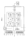
- FIG. 1 shows a diagram representing a battery, a battery management system (BMS), and peripheral devices of the BMS according to aspects of the present invention.
- the hybrid electric vehicle system includes a battery management system 1, a battery 2, a current sensor 3, a cooling fan 4, a fuse 5, a main switch 6, a motor control unit (MTCU) 7, an inverter 8, and a motor generator 9.
- the battery 2 includes a plurality of sub-packs 2a to 2h having a plurality of battery cells coupled in series, a first output terminal 2_OUT1, a second output terminal 2_OUT2, and a safety switch 2_SW.
- the sub-packs 2a to 2h are coupled in series but need not be limited thereto.
- the sub-packs 2a to 2h may be coupled in series with another component or device disposed therebetween.
- the safety switch 2 SW is disposed between the sub-pack 2d and the sub-pack 2e. While 8 sub-packs 2a to 2h are exemplified and each sub-pack is a group of a plurality of battery cells according to aspects of the present invention, it is not limited thereto.
- the battery 2 may include more or fewer sub-packs and battery cells, both of which may be arranged in series or parallel.
- the safety switch 2_SW is manually turned on/off to guarantee the safety of a worker when performing operations on the battery or replacing the battery.
- the safety switch 2_SW is provided between the sub-pack 2d and the sub-pack 2e but is not limited thereto.
- the first output terminal 2_OUT1 and the second output terminal 2_OUT2 are coupled to the inverter 8 via the current sensor 2 and the fuse 5 and the main switch 6, respectively.
- the current sensor 3 measures an output current of the battery 2 and outputs the measured output current to a sensing unit 10 of the BMS 1.
- the current sensor 3 may be a hall current transformer (Hall CT) that uses the Hall Effect via a hall element to measure a current and output an analog current signal corresponding to the measured current value.
- the current sensor 3 may also be an ammeter disposed in a load line or a shunt resistor, which outputs a voltage signal corresponding to a current value through a resistor inserted in the load line.
- the cooling fan 4 cools down heat generated by charging and discharging the battery 2 in response to a control signal from the BMS 1.
- the cooling fan 4 prevents the battery 2 and the charging/discharging efficiency thereof from deteriorating due to temperature increases.
- the fuse 5 prevents an overflow current, which may be caused by a short circuit of the battery 2, from being transmitted to the battery 2. That is, when an over-current is generated, the fuse 5 is disconnects or breaks the circuit so as to interrupt the current from overflowing and damaging the battery 2.
- the main switch 6 turns the battery 2 on and off in response to the control signals of the BMS 1 or control signals of the MTCU 7.
- the main switch 6 further protects the battery 2 from unusual phenomena, such as an overflowing voltage, an overflowing current, and high temperatures.
- the BMS 1 includes a sensing unit 10, a micro control unit (MCU) 20, an internal power supplier 30, a cell balance unit 40, a storage unit 50, a communication unit 60, a protection circuit unit 70, a power-on reset unit 80, and an external interface 90.
- MCU micro control unit
- the BMS 1 includes a sensing unit 10, a micro control unit (MCU) 20, an internal power supplier 30, a cell balance unit 40, a storage unit 50, a communication unit 60, a protection circuit unit 70, a power-on reset unit 80, and an external interface 90.
- MCU micro control unit
- the sensing unit 10 measures a voltage of the battery and transmits the measured voltage to the MCU 20.
- a voltage at an output terminal of the battery will be referred to as a battery voltage.
- the sensing unit 10 may also measure a current of the battery 2 and transmit the measured current to the MCU 20.
- the MCU 20 determines a state of charge (SOC) of the battery 2 based on the battery voltage transmitted from the sensing unit 10, and generates information that indicates the SOC of the battery 2. Then, the MCU 20 transmits the generated information to the MTCU 7 of the vehicle.
- SOC state of charge
- the MCU 20 controls a charge or discharge of the battery 2 by transmitting to the battery 2 a predetermined number of battery charge/discharge pulse pattern waveforms, such that a voltage of the battery 2 can have a predetermined number of maximum and minimum peaks, in order to measure an accurate OCV of the battery 2.
- the alternating charging/discharging of the battery according to the predetermined number of pulse pattern waveforms has the purpose of reducing polarization (or polarized resistance) of the battery 2, then the MCU 20 calculates an accurate OCV by using a portion of the pulse pattern waveforms.
- the MCU 20 sets an OCV setting from which an accurate SOC of the battery is determined by measuring and calculating a voltage of a predetermined number of pulse patterns of a battery charge/discharge pulse pattern waveform generated while the vehicle is being operated.
- the internal power supplier 30 supplies power to the BMS 1 by using a backup battery (not shown).
- the cell balance unit 40 balances the SOC of each cell in the battery 2. That is, cells relatively more charged are discharged, and cells relatively less charged are charged.
- the storage unit 50 stores data of the current SOC and a current state of health (SOH) when the power source of the BMS 1 is turned off.
- the communication unit 60 communicates with the MTCU 7 of the vehicle.
- the protection circuit unit 70 uses firmware elements to protect the battery 2 from shocks, overflowing currents, and low voltages.
- the power-on reset unit 80 resets the overall system when the power source of the BMS 1 is turned on.
- the external interface 90 couples BMS 1 auxiliary devices, such as the cooling fan 4 and the main switch 6, to the MCU 20. While the cooling fan 4 and the main switch 6 are shown as assistance devices for the BMS 1, the BMS 1 is not limited thereto. For example, other auxiliary devices may be included or the present auxiliary devices may be excluded.
- the MTCU 7 determines a torque state based on information from an accelerator, a brake, and a vehicle speed, and controls an output of the motor generator 9 so that the output corresponds to torque information. That is, the MTCU 7 controls a switching operation of the inverter 8, and controls the output of the motor generator 9 so that the output corresponds to the torque information.
- the MTCU 7 receives the SOC of the battery 2 from the MCU 20 through the communication unit 60, and controls the SOC level of the battery 2 toward a target level (e.g., 55%). For example, when the SOC level transmitted from the MCU 20 is lower than 55%, the MTCU 7 controls a switch to control the inverter 8 so as to output power toward the battery 2 and charge the battery 2.
- the MTCU 7 controls the switch of the inverter 8 to output the power toward the motor generator 9 and discharge the battery 2. In such case, current flows from the battery 2 to power the vehicle.
- the inverter 8 controls the battery 2 to be charged or discharged in response to the control signal from the MTCU 7.
- the motor generator 9 uses the electrical energy of the battery to drive the vehicle based on the torque information transmitted from the MTCU 7.
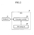
- FIG. 2 shows a schematic diagram of the MCU 20 of the BMS 1 of FIG. 1 .
- the MCU 20 includes a pulse pattern controller 210 and an OCV setting unit 220.
- the pulse pattern controller 210 determines whether the battery 2 is fully charged or fully discharged, and discharges the battery 2 to a SOC value of 60% at a 1C rate when the battery 2 is fully charged and charges the battery 2 to a SOC value of 60% at a 1C rate when the battery 2 is fully discharged.
- a charge current and a discharge current of a battery are measured in C-rate, which represents the amount of charge/discharge current required for fully charging/discharging the battery within one hour.
- the pulse pattern controller 210 charges or discharges the battery 2 to a SOC value of 60% at a 1C rate, and controls the charge/discharge operation of the battery 2 so as to control a voltage of the battery 2 to have a plurality of pulse pattern waveforms.
- each of the plurality of pulse pattern waveforms is formed of a plurality of pulse patterns, each of which is discharging and charging the battery 2 once.
- the pulse pattern controller 210 eliminates polarization and internal resistance in the battery 2, by using the battery charge/discharge pulse pattern waveform.
- the pulse pattern controller 210 controls a SOC of the battery 2 toward a constant level when the battery 2 is fully charged or fully discharged and controls the charge/discharge operation of the battery 2 so as to generate the plurality of battery pulse patterns. In more detail, the pulse pattern controller 210 determines whether the battery 2 is fully charged or fully discharged, discharges the battery 2 to a SOC value of 60% at a 1C rate when the battery 2 is fully charged, and charges the battery 2 to a SOC value of 60% at a 1C rate when the battery 2 is fully discharged.
- the pulse pattern controller 210 controls a battery charge/discharge pulse pattern waveform after the battery 2 is charged or discharged.
- each of the plurality of battery charge/discharge pulse pattern waveforms is formed of 10 pulse patterns, and each pulse pattern repeats charge and discharge of the battery 2 once.
- the pulse pattern controller 210 counts a waveform formed of 10 pulses, from the first pulse to the 10th pulse, and stops counting after the pulse pattern controller 210 counts 10 times.
- the pulse pattern controller stores a maximum peak voltage and a minimum peak voltage among battery voltages of the detected pulse patterns.
- the detected pulse pattern may include at least the last pulse among the plurality of pulse patterns.
- the OCV setting unit 220 adds the maximum peak voltage and the minimum peak voltage of pulse pattern from the 8th detected pulse pattern to the 10th detected pulse pattern transmitted from the pulse pattern controller 210, and calculates an average of the maximum and minimum peak voltages. Then, the OCV setting unit 220 sets the calculated average value to an OCV setting.
- the OCV setting unit 220 integrates a voltage of a detected pulse pattern that may include at least the last pulse and divides the integration result by time, and then sets a division result to the OCV setting.
- the OCV setting unit 220 may set an average value of maximum and minimum peak voltages of three detected pulse patterns among the plurality of pulse patterns, but this is not restrictive.
- the OCV setting unit 220 may use the last pulse or the OCV setting unit 220 may average several previous pulses to set the OCV setting.
- the described embodiment may be modified in various different ways.
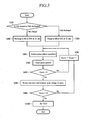
- FIG. 3 is a flowchart representing a driving method of the battery management system (BMS 1) according to aspects of the present invention.
- the MCU 20 of the BMS 1 determines whether the battery 2 is fully charged or fully discharged. When it is determined in operation (S100) that the battery 2 is fully charged, the MCU 20 discharges the fully charged battery to a predetermined SOC level of 60% at a 1C rate in operation (S200). When it is determined in operation (S100) that the battery 2 is fully discharged, the MCU 20 charges the fully discharged battery 2 to the predetermined SOC level of 60% at a 1C rate in operation (S300).
- a charge current and a discharge current of a battery is measured in C-rate, which represents the amount of charge/discharge current required to fully charge/discharge the battery within one hour.
- the predetermined SOC level needs not be 60%.
- the MCU 20 controls a voltage of the battery 2 by applying a battery charge/discharge pulse pattern waveform in operation (S400).
- the battery charge/discharge pulse pattern waveform is formed of 10 pulse patterns, wherein each of the 10 pulse patterns charges the battery 2 and discharges the battery 2 once.
- the MCU 20 counts the battery charge/discharge pulse patterns in operation (S500). Then, the MCU 20 determines whether it has counted the pulse pattern more than 8 times in operation (S600). When it is determined in operation (S600) that the MCU 20 has counted the pulse pattern fewer than 8 times, the MCU 20 increments the number of counting by 1, in operation (S700). Then, the MCU 20 returns to the operation (S400).
- the MCU 200 sets the 8th pulse pattern to the 10th pulse pattern as detected pulse patterns, and stores a maximum peak voltage and a minimum peak voltage of each pulse pattern of the detected pulse patterns in operation (S800). Then, whether counting of the pulse pattern has been performed 10 times is determined in operation (S900). When a result of the determination in operation (S900) shows that the counting of the pulse pattern has been performed less than 10 times, the counting of the pulse pattern is performed one more time and incremented in operation (S700). Then, the process is returned to operation (S400).
- the MCU 200 calculates an average value of the maximum peak voltages and the minimum peak voltages from the detected pulse patterns stored in operation (S800) and the average value (of the maximum and minimum voltages) is set as the OCV setting, in operation (S1000). The OCV setting is then used to estimate the SOC of the battery 2.
- the driving method is described as averaging the maximum and minimum peak voltages of the 8th through 10th pulse patterns
- the MCU 200 is not limited thereto.
- the OCV setting may be determined by only averaging the minimum peak voltages of the 8th through 10th pulse patterns.
- only the maximum and minimum peak voltages of the 10th pulse pattern may be averaged to determine the OCV setting from which the SOC of the battery 2 is determined.
- the battery management system and the driving method according to aspects of the present invention use a detected pulse pattern to set an OCV setting from which a more accurate SOC may be estimated.
- the battery management system determines whether the battery is in the fully-charged state or in the fully-discharged state, and charges or discharges the battery to a predetermined SOC level of 60% at a 1C rate according to a result of the determination. Then, the battery management system controls a charge/discharge pulse pattern waveform of the battery and counts a pulse pattern. A maximum peak voltage and a minimum peak voltage of each counted pulse pattern is stored, and an average value of maximum peak voltages and the minimum peak voltages of the 8th counted pulse pattern to the 10th counted pulse pattern is calculated. The calculated average value is set as the OCV setting.
- the polarization voltage can be decreased in order to reduce the polarization phenomenon.
- the pulse pattern voltage is compulsorily applied inside the battery 2 and the polarization voltage can be decreased by the pulse pattern voltage.
- the more pulses are applied to the battery the more the polarization voltage can be decreased.
- the period of applying the pulses is restricted. Therefore, to exactly calculate the OCV, the present invention averages only the last pulses. Accordingly, an accurate OCV can be set while the vehicle is operating and/or accelerating or while the battery is under a load. Accordingly, the battery management system and the driving method of the battery management system can measure an accurate SOC.
- errors in SOC estimation can be reduced by reducing an error that may be generated when setting an OCV setting, and therefore overcharge and over-discharge of the battery can be prevented.
Landscapes
- Engineering & Computer Science (AREA)
- Power Engineering (AREA)
- Life Sciences & Earth Sciences (AREA)
- Sustainable Development (AREA)
- Sustainable Energy (AREA)
- Transportation (AREA)
- Mechanical Engineering (AREA)
- Secondary Cells (AREA)
- Charge And Discharge Circuits For Batteries Or The Like (AREA)
- Tests Of Electric Status Of Batteries (AREA)
- Electric Propulsion And Braking For Vehicles (AREA)
Claims (19)
- Procédé d'attaque d'un système de gestion de batterie (1) pour commander la charge/décharge d'une batterie (2), le procédé d'attaque comprenant :la détermination du fait que la batterie (2) est totalement chargée ou totalement déchargée ;la charge/décharge de la batterie (2) à un état de charge (SOC pour « State Of Charge ») d'un niveau prédéterminé ;la génération d'une forme d'onde de motifs d'impulsions de charge/décharge de batterie comprenant une pluralité de motifs d'impulsions ;le procédé d'attaque étant caractérisé par les étapes consistant à :compter les motifs d'impulsions ;calculer une valeur moyenne d'une tension de pic maximale et d'une tension de pic minimale d'au moins un motif d'impulsions compté comprenant le dernier motif d'impulsions ; etétablir la valeur moyenne à une valeur de tension de circuit ouvert (OCV pour « Open Circuit Voltage »).
- Procédé d'attaque selon la revendication 1, dans lequel chacun de la pluralité de motifs d'impulsions charge et décharge la batterie (2) une fois.
- Procédé d'attaque selon l'une des revendications précédentes, comprenant de plus l'estimation de l'état de charge (SOC) de la batterie à partir de la valeur de tension en circuit ouvert (OCV).
- Procédé d'attaque selon l'une des revendications précédentes, dans lequel la pluralité de motifs d'impulsions comprend 10 impulsions.
- Procédé d'attaque selon la revendication 4, dans lequel l'au moins un motif d'impulsions détecté comprend un 8ème, un 9ème et le dernier motifs d'impulsions.
- Procédé d'attaque selon la revendication 5, dans lequel la valeur moyenne comprend une moyenne des tensions de pic maximales et des tensions de pic minimales du 8ème, du 9ème et du dernier motifs d'impulsions.
- Procédé d'attaque selon l'une des revendications précédentes, comprenant de plus la mémorisation de la tension de pic maximale et de la tension de pic minimale de l'au moins un motif d'impulsions détecté.
- Procédé d'attaque selon l'une des revendications 1 à 3, dans lequel la valeur moyenne comprend une moyenne de la totalité des tensions de pic maximales et des tensions de pic minimales de la pluralité de motifs d'impulsions.
- Système de gestion de batterie (1) pour un véhicule, comprenant :une unité de détection (10) pour mesurer une tension d'une batterie (2) ; etune unité de commande principale (MCU 20) pour commander une charge/décharge de la batterie (2), pour générer une forme d'onde de motifs d'impulsions de charge/décharge comprenant une pluralité de motifs d'impulsions, pour mesurer au moins une valeur de tension d'au moins un motif d'impulsions, et pour établir une moyenne de l'au moins une valeur de tension mesurée à une valeur de tension de circuit ouvert (OCV) à partir de laquelle est estimé un état de charge (SOC) de la batterie (2),dans lequel l'unité de détection (10) transmet l'au moins une valeur de tension mesurée à l'unité de commande principale (MCU 20), etcaractérisé en ce que l'unité de commande principale (MCU 20) comprend :un dispositif de commande de motifs d'impulsions (210) pour compter un nombre des motifs d'impulsions et pour mémoriser une tension de pic maximale et une tension de pic minimale d'un motif d'impulsions détecté comprenant au moins le dernier motif d'impulsions du nombre de motifs d'impulsions compté ; etune unité d'établissement de tension de circuit ouvert (OCV) (220) pour calculer une valeur moyenne de la tension de pic maximale et de la tension de pic minimale du nombre de motifs d'impulsions compté, et établir la valeur moyenne à une valeur de tension de circuit ouvert (OCV).
- Système de gestion de batterie selon la revendication 9, dans lequel l'unité de commande principale (MCU 20) charge la batterie (2) à un niveau prédéterminé si la batterie est totalement déchargée, et l'unité de commande principale (MCU 20) décharge la batterie (2) au niveau prédéterminé si la batterie (2) est totalement chargée.
- Système de gestion de batterie selon la revendication 10, dans lequel le niveau d'état de charge (SOC) prédéterminé est de 60%.
- Système de gestion de batterie selon l'une des revendications 10 et 11, dans lequel l'unité de commande principale (MCU 20) génère la forme d'onde de motifs d'impulsions de charge/décharge après que la batterie (2) ait été chargée/déchargée au niveau prédéterminé.
- Système de gestion de batterie selon l'une des revendications 9 à 12, dans lequel chacun de la pluralité de motifs d'impulsions charge et décharge la batterie une fois.
- Système de gestion de batterie selon l'une des revendications 9 à 13, dans lequel la moyenne comprend une moyenne de la tension de pic maximale et de la tension de pic minimale d'au moins un motif d'impulsions.
- Système de gestion de batterie selon l'une des revendications 9 à 14, dans lequel la pluralité de motifs d'impulsions comprend 10 motifs d'impulsions.
- Système de gestion de batterie selon la revendication 15, dans lequel la moyenne comprend une moyenne des tensions de pic maximale et minimale d'un 10ème motif d'impulsions.
- Système de gestion de batterie selon la revendication 15, dans lequel la moyenne comprend une moyenne des tensions de pic maximale et minimale d'un 8ème, d'un 9ème et d'un 10ème motifs d'impulsions.
- Système de gestion de batterie selon l'une des revendications 9 à 17, dans lequel l'unité de commande principale (MCU 20) génère la forme d'onde de motifs d'impulsions de charge/décharge tandis que le véhicule fonctionne et/ou tandis que le véhicule accélère.
- Système de gestion de batterie selon l'une des revendications 9 à 18, dans lequel l'unité de commande principale (MCU 20) génère la forme d'onde de motifs d'impulsions de charge/décharge tandis que la batterie (2) supporte une charge.
Applications Claiming Priority (1)
| Application Number | Priority Date | Filing Date | Title |
|---|---|---|---|
| KR1020060107224A KR100839384B1 (ko) | 2006-11-01 | 2006-11-01 | 배터리 관리 시스템 및 그 구동방법 |
Publications (3)
| Publication Number | Publication Date |
|---|---|
| EP1919060A2 EP1919060A2 (fr) | 2008-05-07 |
| EP1919060A3 EP1919060A3 (fr) | 2008-05-21 |
| EP1919060B1 true EP1919060B1 (fr) | 2012-03-14 |
Family
ID=39137002
Family Applications (1)
| Application Number | Title | Priority Date | Filing Date |
|---|---|---|---|
| EP07119357A Not-in-force EP1919060B1 (fr) | 2006-11-01 | 2007-10-26 | Système de gestion de batterie et son procédé de commande |
Country Status (5)
| Country | Link |
|---|---|
| US (1) | US20080100265A1 (fr) |
| EP (1) | EP1919060B1 (fr) |
| JP (1) | JP4949086B2 (fr) |
| KR (1) | KR100839384B1 (fr) |
| CN (1) | CN101174710B (fr) |
Families Citing this family (26)
| Publication number | Priority date | Publication date | Assignee | Title |
|---|---|---|---|---|
| KR100737003B1 (ko) * | 2005-12-14 | 2007-07-09 | 현대자동차주식회사 | 직렬 및 병렬 하이브리드 자동차에서의 최적 운전점결정방법 |
| US8264207B2 (en) * | 2007-10-16 | 2012-09-11 | Ford Global Technologies, Llc | Method and system for pulse charging an automotive battery |
| KR101187766B1 (ko) * | 2008-08-08 | 2012-10-05 | 주식회사 엘지화학 | 배터리 셀의 전압 변화 거동을 이용한 셀 밸런싱 장치 및 방법 |
| JP5448865B2 (ja) * | 2010-01-18 | 2014-03-19 | 三菱重工業株式会社 | 電池システム |
| JP5704108B2 (ja) * | 2012-03-30 | 2015-04-22 | トヨタ自動車株式会社 | 電池システムおよび推定方法 |
| CN103802684A (zh) * | 2012-11-03 | 2014-05-21 | 贺怀远 | 电动汽车充、放电装置 |
| JP5704156B2 (ja) * | 2012-12-25 | 2015-04-22 | 株式会社デンソー | 蓄電池システム |
| US20140350875A1 (en) * | 2013-05-27 | 2014-11-27 | Scott Allen Mullin | Relaxation model in real-time estimation of state-of-charge in lithium polymer batteries |
| US9915703B2 (en) | 2013-10-16 | 2018-03-13 | Ford Global Technologies, Llc | Voltage sensing system and method |
| CN103529394B (zh) * | 2013-10-24 | 2015-09-09 | 国家电网公司 | 一种储能系统容量检测装置及方法 |
| CN104714181B (zh) * | 2013-12-11 | 2017-10-27 | 广州汽车集团股份有限公司 | 一种获取电压与电池荷电状态关系的方法和系统 |
| KR101630409B1 (ko) * | 2014-06-11 | 2016-06-14 | 주식회사 엘지화학 | 이차전지 배터리 팩의 상태 추정장치와 방법 및 이를 이용한 배터리 팩 |
| CN104527448B (zh) * | 2015-01-04 | 2016-08-17 | 南车株洲电力机车有限公司 | 一种电压均衡控制方法和系统 |
| CN104908605A (zh) * | 2015-06-15 | 2015-09-16 | 王凤成 | 一种模块化锂电池的bms分散检测集中管理系统 |
| JP6421986B2 (ja) * | 2015-07-29 | 2018-11-14 | スズキ株式会社 | 二次電池の充電率推定方法、充電率推定装置、及び健全度推定装置 |
| US11309717B2 (en) | 2016-09-26 | 2022-04-19 | Samsung Electronics Co., Ltd. | Apparatus and method for battery management |
| KR102634814B1 (ko) * | 2016-11-16 | 2024-02-07 | 삼성전자주식회사 | 배터리 상태 추정 방법 및 장치 |
| CN106501732A (zh) * | 2016-12-14 | 2017-03-15 | 中国电力科学研究院 | 一种用于对时钟电池剩余电量进行评估的方法及系统 |
| US10996281B2 (en) | 2016-12-28 | 2021-05-04 | Silicon Laboratories Inc. | Charge measurement calibration in a system using a pulse frequency modulated DC-DC converter |
| DE102017126901B4 (de) * | 2016-12-28 | 2024-10-24 | Silicon Laboratories Inc. | Ladungsmessung in einem System unter Verwendung eines impulsfrequenzmodulierten DC-DC-Wandlers |
| KR102458526B1 (ko) * | 2018-02-07 | 2022-10-25 | 주식회사 엘지에너지솔루션 | 배터리의 동작 상태에 따라 soc를 추정하는 장치 및 방법 |
| CN112260372B (zh) * | 2020-12-23 | 2021-04-27 | 江苏时代新能源科技有限公司 | 一种电池均衡方法、装置及电池管理系统 |
| KR102893180B1 (ko) * | 2021-01-28 | 2025-12-01 | 컨템포러리 엠퍼렉스 테크놀로지 (홍콩) 리미티드 | 충전 방법, 전원 배터리의 배터리 관리 시스템 및 충전 파일 |
| JP7536886B2 (ja) * | 2022-02-18 | 2024-08-20 | 寧徳時代新能源科技股▲分▼有限公司 | 電池モジュール充電システムとその制御方法、装置、ユニット及び記憶媒体 |
| KR102827611B1 (ko) * | 2022-03-03 | 2025-07-01 | 주식회사 민테크 | 배터리 상태 추정 방법 |
| KR20240162881A (ko) * | 2023-05-09 | 2024-11-18 | 주식회사 엘지에너지솔루션 | 배터리 관리 장치 및 그것의 동작 방법 |
Family Cites Families (9)
| Publication number | Priority date | Publication date | Assignee | Title |
|---|---|---|---|---|
| FR2421430A1 (fr) * | 1978-03-29 | 1979-10-26 | Peugeot | Dispositif simulateur du fonctionnement d'une batterie d'accumulateur, notamment d'une batterie de traction pour vehicule electrique |
| US5523667A (en) * | 1992-01-27 | 1996-06-04 | Feldstein; Robert S. | Alkaline battery charger and method of operating same |
| FI112730B (fi) * | 1995-09-05 | 2003-12-31 | Nokia Corp | Akkujännitteen määrittäminen latauksen aikana ja akun latauslaite |
| AUPO917297A0 (en) * | 1997-09-15 | 1997-10-09 | Commonwealth Scientific And Industrial Research Organisation | Charging of batteries |
| US6366056B1 (en) * | 1999-06-08 | 2002-04-02 | Enrev Corporation | Battery charger for lithium based batteries |
| KR100505382B1 (ko) * | 2003-06-20 | 2005-08-02 | 주식회사 파워로직스 | 하이브리드 전기자동차의 배터리 잔존용량 산출시기결정방법 |
| US7221125B2 (en) * | 2003-11-06 | 2007-05-22 | Y. Ding | System and method for charging a battery |
| US7442470B2 (en) * | 2004-10-12 | 2008-10-28 | Matsushita Electric Industrial Co., Ltd. | High power output non-aqueous electrolyte secondary battery |
| KR20060098146A (ko) * | 2005-03-09 | 2006-09-18 | 주식회사 엘지화학 | 온도에 따른 오픈 회로 전압 히스테레시스를 이용한 배터리의 잔존 용량 초기값 설정 방법 |
-
2006
- 2006-11-01 KR KR1020060107224A patent/KR100839384B1/ko not_active Expired - Fee Related
-
2007
- 2007-03-13 JP JP2007063359A patent/JP4949086B2/ja not_active Expired - Fee Related
- 2007-09-10 US US11/852,575 patent/US20080100265A1/en not_active Abandoned
- 2007-09-30 CN CN2007101514002A patent/CN101174710B/zh not_active Expired - Fee Related
- 2007-10-26 EP EP07119357A patent/EP1919060B1/fr not_active Not-in-force
Also Published As
| Publication number | Publication date |
|---|---|
| KR100839384B1 (ko) | 2008-06-19 |
| EP1919060A2 (fr) | 2008-05-07 |
| JP2008116433A (ja) | 2008-05-22 |
| CN101174710A (zh) | 2008-05-07 |
| JP4949086B2 (ja) | 2012-06-06 |
| EP1919060A3 (fr) | 2008-05-21 |
| US20080100265A1 (en) | 2008-05-01 |
| KR20080039654A (ko) | 2008-05-07 |
| CN101174710B (zh) | 2012-03-07 |
Similar Documents
| Publication | Publication Date | Title |
|---|---|---|
| EP1919060B1 (fr) | Système de gestion de batterie et son procédé de commande | |
| EP1777794B1 (fr) | Système de gestion de batterie et méthode pour la détermination de l'état de charge d'une batterie | |
| US8060322B2 (en) | Battery management system and driving method thereof | |
| EP1801947B1 (fr) | Procédé de compensation de l'état de charge d'une batterie et système de gestion de batterie | |
| EP1914559B1 (fr) | Système de gestion de batterie (BMS) et son procédé de commande | |
| EP1801605B1 (fr) | Procédé de compensation de l'état de charge d'une batterie et système de gestion de batterie l'utilisant | |
| EP1801604B1 (fr) | Procédé pour compenser l'état de charge d'une batterie et système de gestion de batterie l'utilisant | |
| EP1897772B1 (fr) | Système de gestion de batterie et son procédé de commande | |
| US7652449B2 (en) | Battery management system and driving method thereof | |
| EP1801606B1 (fr) | Procédé de compensation de l'état de charge d'une batterie, système de gestion de la batterie utilisant ce procédé, et véhicule hybride comportant le système de gestion de batterie | |
| US7634369B2 (en) | Battery management system (BMS) and driving method thereof | |
| US7800345B2 (en) | Battery management system and method of operating same | |
| US7684942B2 (en) | Battery management system and driving method thereof | |
| KR101552903B1 (ko) | 배터리 관리 시스템 및 방법 | |
| JP2008064740A (ja) | バッテリー管理システム及びその駆動方法 | |
| KR101117636B1 (ko) | 배터리의 soc추정 방법 및 이를 이용한 배터리 관리시스템 |
Legal Events
| Date | Code | Title | Description |
|---|---|---|---|
| PUAI | Public reference made under article 153(3) epc to a published international application that has entered the european phase |
Free format text: ORIGINAL CODE: 0009012 |
|
| PUAL | Search report despatched |
Free format text: ORIGINAL CODE: 0009013 |
|
| 17P | Request for examination filed |
Effective date: 20071026 |
|
| AK | Designated contracting states |
Kind code of ref document: A2 Designated state(s): AT BE BG CH CY CZ DE DK EE ES FI FR GB GR HU IE IS IT LI LT LU LV MC MT NL PL PT RO SE SI SK TR |
|
| AX | Request for extension of the european patent |
Extension state: AL BA HR MK RS |
|
| AK | Designated contracting states |
Kind code of ref document: A3 Designated state(s): AT BE BG CH CY CZ DE DK EE ES FI FR GB GR HU IE IS IT LI LT LU LV MC MT NL PL PT RO SE SI SK TR |
|
| AX | Request for extension of the european patent |
Extension state: AL BA HR MK RS |
|
| AKX | Designation fees paid |
Designated state(s): DE FR GB HU |
|
| GRAP | Despatch of communication of intention to grant a patent |
Free format text: ORIGINAL CODE: EPIDOSNIGR1 |
|
| GRAS | Grant fee paid |
Free format text: ORIGINAL CODE: EPIDOSNIGR3 |
|
| GRAA | (expected) grant |
Free format text: ORIGINAL CODE: 0009210 |
|
| AK | Designated contracting states |
Kind code of ref document: B1 Designated state(s): DE FR GB HU |
|
| REG | Reference to a national code |
Ref country code: GB Ref legal event code: FG4D |
|
| RIN1 | Information on inventor provided before grant (corrected) |
Inventor name: TAE, YONG-JUN,LEGAL & IP TEAM Inventor name: LIM, GYE-JONG,LEGAL & IP TEAM Inventor name: KIM, BEOM-GYU,LEGAL & IP TEAM Inventor name: YUN, HAN-SEOK,LEGAL & IP TEAM Inventor name: CHOI, SOO-SEOK,LEGAL & IP TEAM Inventor name: LEE, YOUNG-JO,LEGAL & IP TEAM Inventor name: PARK, HO-YOUNG,LEGAL & IP TEAM |
|
| REG | Reference to a national code |
Ref country code: DE Ref legal event code: R096 Ref document number: 602007021270 Country of ref document: DE Effective date: 20120503 |
|
| PLBE | No opposition filed within time limit |
Free format text: ORIGINAL CODE: 0009261 |
|
| STAA | Information on the status of an ep patent application or granted ep patent |
Free format text: STATUS: NO OPPOSITION FILED WITHIN TIME LIMIT |
|
| 26N | No opposition filed |
Effective date: 20121217 |
|
| REG | Reference to a national code |
Ref country code: DE Ref legal event code: R097 Ref document number: 602007021270 Country of ref document: DE Effective date: 20121217 |
|
| PG25 | Lapsed in a contracting state [announced via postgrant information from national office to epo] |
Ref country code: HU Free format text: LAPSE BECAUSE OF FAILURE TO SUBMIT A TRANSLATION OF THE DESCRIPTION OR TO PAY THE FEE WITHIN THE PRESCRIBED TIME-LIMIT Effective date: 20071026 |
|
| REG | Reference to a national code |
Ref country code: FR Ref legal event code: PLFP Year of fee payment: 9 |
|
| PGFP | Annual fee paid to national office [announced via postgrant information from national office to epo] |
Ref country code: FR Payment date: 20150923 Year of fee payment: 9 |
|
| PGFP | Annual fee paid to national office [announced via postgrant information from national office to epo] |
Ref country code: GB Payment date: 20151021 Year of fee payment: 9 Ref country code: DE Payment date: 20151020 Year of fee payment: 9 |
|
| REG | Reference to a national code |
Ref country code: DE Ref legal event code: R119 Ref document number: 602007021270 Country of ref document: DE |
|
| GBPC | Gb: european patent ceased through non-payment of renewal fee |
Effective date: 20161026 |
|
| REG | Reference to a national code |
Ref country code: FR Ref legal event code: ST Effective date: 20170630 |
|
| PG25 | Lapsed in a contracting state [announced via postgrant information from national office to epo] |
Ref country code: FR Free format text: LAPSE BECAUSE OF NON-PAYMENT OF DUE FEES Effective date: 20161102 Ref country code: DE Free format text: LAPSE BECAUSE OF NON-PAYMENT OF DUE FEES Effective date: 20170503 Ref country code: GB Free format text: LAPSE BECAUSE OF NON-PAYMENT OF DUE FEES Effective date: 20161026 |