EP1919065A2 - Stromversorgungssystem für Luft- und Raumfahrt unter Verwendung eines multifunktionellen Gleichspannungswandlers - Google Patents
Stromversorgungssystem für Luft- und Raumfahrt unter Verwendung eines multifunktionellen Gleichspannungswandlers Download PDFInfo
- Publication number
- EP1919065A2 EP1919065A2 EP07119554A EP07119554A EP1919065A2 EP 1919065 A2 EP1919065 A2 EP 1919065A2 EP 07119554 A EP07119554 A EP 07119554A EP 07119554 A EP07119554 A EP 07119554A EP 1919065 A2 EP1919065 A2 EP 1919065A2
- Authority
- EP
- European Patent Office
- Prior art keywords
- bus
- power
- converter
- voltage
- battery
- Prior art date
- Legal status (The legal status is an assumption and is not a legal conclusion. Google has not performed a legal analysis and makes no representation as to the accuracy of the status listed.)
- Withdrawn
Links
Images


Classifications
-
- H—ELECTRICITY
- H02—GENERATION; CONVERSION OR DISTRIBUTION OF ELECTRIC POWER
- H02J—ELECTRIC POWER NETWORKS; CIRCUIT ARRANGEMENTS OR SYSTEMS FOR SUPPLYING OR DISTRIBUTING ELECTRIC POWER; SYSTEMS FOR STORING ELECTRIC ENERGY
- H02J7/00—Circuit arrangements for charging or discharging batteries or for supplying loads from batteries
- H02J7/34—Parallel operation in networks using both storage and other DC sources, e.g. providing buffering
-
- H—ELECTRICITY
- H02—GENERATION; CONVERSION OR DISTRIBUTION OF ELECTRIC POWER
- H02J—ELECTRIC POWER NETWORKS; CIRCUIT ARRANGEMENTS OR SYSTEMS FOR SUPPLYING OR DISTRIBUTING ELECTRIC POWER; SYSTEMS FOR STORING ELECTRIC ENERGY
- H02J4/00—Circuit arrangements for mains or distribution networks not specified as AC or DC; Circuit arrangements for mains or distribution networks combining AC and DC sections or sub-networks
- H02J4/20—Networks integrating separated AC and DC power sections
- H02J4/25—Networks integrating separated AC and DC power sections for transfer of electric power between AC and DC networks, e.g. for supplying the DC section within a load from an AC mains system
-
- H—ELECTRICITY
- H02—GENERATION; CONVERSION OR DISTRIBUTION OF ELECTRIC POWER
- H02J—ELECTRIC POWER NETWORKS; CIRCUIT ARRANGEMENTS OR SYSTEMS FOR SUPPLYING OR DISTRIBUTING ELECTRIC POWER; SYSTEMS FOR STORING ELECTRIC ENERGY
- H02J7/00—Circuit arrangements for charging or discharging batteries or for supplying loads from batteries
- H02J7/02—Circuit arrangements for charging or discharging batteries or for supplying loads from batteries for charging batteries from AC mains by converters
-
- Y—GENERAL TAGGING OF NEW TECHNOLOGICAL DEVELOPMENTS; GENERAL TAGGING OF CROSS-SECTIONAL TECHNOLOGIES SPANNING OVER SEVERAL SECTIONS OF THE IPC; TECHNICAL SUBJECTS COVERED BY FORMER USPC CROSS-REFERENCE ART COLLECTIONS [XRACs] AND DIGESTS
- Y02—TECHNOLOGIES OR APPLICATIONS FOR MITIGATION OR ADAPTATION AGAINST CLIMATE CHANGE
- Y02T—CLIMATE CHANGE MITIGATION TECHNOLOGIES RELATED TO TRANSPORTATION
- Y02T50/00—Aeronautics or air transport
- Y02T50/50—On board measures aiming to increase energy efficiency
Definitions
- the present invention relates to electrical systems, and more particularly to a DC to DC converter for an electrical power system.
- Electric systems used in complex environments such as aerospace systems, more electric aircraft systems, industrial environments, vehicles, etc., include a large number of electric systems and modules.
- various electric systems and modules may need to be connected to electric power, disconnected from electric power, maintained in a powered-up state, etc., at various times.
- various electric systems and modules in a complex environment may require amounts and type of electrical power specific to each system/ module.
- the power levels required by various parts of the complex environment may also depend on the operational stage of the environment. For example, different levels of power may be needed during the start-up of main engines or auxiliary engine, during continuous operation, or during a battery recharge, in a complex environment such as an aircraft.
- auxiliary power unit APU
- main DC power such as, for example 28Vdc power
- the three distinct sets of hardware are an AC/DC and DC/AC converter system for starting the APU or engine, a Transformer Rectifier Unit (TRU) or Regulated Transformer Rectifier Unit (RTRU) for the supply of the main DC power, such as 28Vdc main power, and a battery charger for charging a battery.
- TRU Transformer Rectifier Unit
- RTRU Regulated Transformer Rectifier Unit
- the large number of units used to provide main DC power and engine start power negatively impact the reliability of the aircraft, as failure or malfunction of one of the units will affect the power availability and the start procedures.
- the large number of units leads to weight, volume, and cost increases for the aircraft.
- Disclosed embodiments of this application address these and other issues by utilizing a multi-functional DC/DC converter that is used as a main DC supply source and as a battery charger when operating in a forward direction, and as a battery power converter to supply power for a starting APU converter, when operating in a reverse direction.
- the multi-functional DC/DC converter replaces multiple units: the TRU or RTRU, and the battery charger.
- An aerospace electrical power DC subsystem using the multi-functional DC/DC converter to start an APU or engine, and recharge a battery leads to significant weight, volume and cost savings, and provides more reliable power functions for an aircraft.
- a multi-functional apparatus for regulating voltage comprises: a DC to DC converter, wherein the DC to DC converter is controlled to operate in a first direction to receive a DC voltage from a first bus and to output a first regulated DC voltage adjusted to charge a battery, wherein the first bus receives power from a second bus, and is controlled to operate in a second direction to receive a battery DC voltage from the battery and to output a second regulated DC voltage to the first bus, to power a load independently or in combination with the second bus.
- an aerospace electrical power DC system comprises: a battery; a bi-directional DC to DC converter operating in a first direction and in a second direction, wherein in the first direction, the DC to DC converter receives a DC voltage from an AC power bus through a rectification system operationally connected to the AC power bus, and outputs a first regulated DC voltage to a constant voltage bus to charge a battery, and in the second direction, the DC to DC converter receives a battery DC voltage from the battery and outputs a second regulated DC voltage for starting a load independently or in combination with the AC power bus.
- an aerospace DC power supply system utilizes a single DC to DC converter to supply a constant DC power bus using rectified power from an aircraft AC bus, and charge a battery continuously connected to the constant DC power bus, wherein the system further utilizes the single DC to DC converter to start an auxiliary power unit using the battery, upon experiencing a condition that power from the aircraft AC bus is insufficient or not available to start the auxiliary power unit.
- FIG. 1 is a general block diagram of an electrical system using a multi-functional DC/DC converter according to an embodiment of the present invention
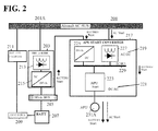
- FIG. 2 is a block diagram of a typical/ conventional subsystem for aircraft.
- FIG. 3 is a block diagram illustrating an aerospace electrical power DC subsystem configuration using a multi-functional DC/DC converter according to an embodiment of the present invention.
- FIG. 1 is a general block diagram of an electrical system using a multi-functional DC/DC converter according to an embodiment of the present invention.
- the electrical system 100 illustrated in FIG.1 includes the following components: a power bus 201; conversion systems 317; loads 231; backup power systems 105; and a multi-functional DC/DC converter 315. Operation of the electrical system 100 in FIG. 1 will become apparent from the following discussion.
- Electrical system 100 may be associated with environments with electrical components, such as an aircraft, a ship, a train, a laboratory facility, etc.
- Power bus 201 provides electrical power to loads 231, either directly or through conversion systems 317.
- Power bus 201 handles wattage power that can be on the order of W, kW, hundreds of kW, MW, etc., and voltages that can be on the order of Volts, hundreds to thousands of Volts, etc.
- the power bus 201 is supplied by generators, transformer-rectifiers, etc.
- Conversion systems 317 receive energy from power bus 201, and provide electrical energy to loads 231. Conversion systems 317 include electrical circuits and components such as transformers, rectifiers, converters, filters, etc.
- Loads 231 are systems that enable functioning of services onboard a vehicle, in an aircraft, in a lab, etc.
- Loads 231 may include an auxiliary power unit, an engine start generator, a cabin air compressor, etc.
- Backup power systems 105 include energy storage devices, such as batteries, fuel cells, capacitors, etc.
- the backup power systems 105 are charged by energy provided by the multi-functional DC/DC converter 315.
- the backup power systems 105 may also use their stored energy to power loads 231, via the multi-functional DC/DC converter 315.
- FIG. 2 is a block diagram of a typical/ conventional power subsystem 200 for aircraft.
- APU auxiliary power unit
- main 28Vdc power make use of three distinct sets of hardware: an AC/DC + DC/AC converter for starting the APU or engine; a Transformer Rectifier Unit (TRU) or Regulated Transformer Rectifier Unit (RTRU) for the supply of 28Vdc main power; and a battery charger for battery charging.
- TRU Transformer Rectifier Unit
- RTRU Regulated Transformer Rectifier Unit
- the TRU 203 for the supply of 28Vdc main power includes a transformer and a rectifier 213.
- the RTRU 203 for the supply of 28Vdc main power includes a transformer or autotransformer, a rectifier 213, and a DC/DC 28Vdc converter 215.
- the TRU or RTRU 203 receives AC power from the aircraft AC bus 201A, and outputs DC power to the 28Vdc bus 205.
- a TRU is unsuitable for charging batteries that are used as backup power sources or auxiliary power supplies, because a TRU has a varying output voltage which does not enable a constant potential charging mode or constant current charging mode.
- a RTRU can provide a constant output DC voltage and hence charge batteries at constant potential.
- a classic RTRU does not limit the current flowing into the battery, and does not control the amount of trickle charge, which leads to battery electrolyte loss. Because of the problems TRUs and RTRUs pose for battery charging, a separate battery charger 211 is typically used to charge the batteries 207 used as backup power sources or auxiliary power supplies.
- the battery charger 211 receives power from the aircraft AC bus 201A, and outputs power to the hot battery bus 209 and to battery 207.
- the 28Vdc bus 205 also receives DC power from battery 207.
- the 28Vdc bus 205 Having received DC power from the battery 207, the 28Vdc bus 205 then provides 28Vdc for start of the APU start converter 217 and consequently of the APU 231A.
- an AC/DC converter 219 and a DC/AC converter 221 are part of the APU start converter 217.
- the AC/DC converter 219 includes a 28Vdc DC/DC converter 225 and a rectifier 227.
- the 28Vdc DC/DC converter 225 converts the 28V voltage coming from the 28Vdc bus 205 to the DC voltage level required for the DC bus 229.
- the rectifier 227 converts the AC voltage coming from the aircraft AC bus 201A to a DC voltage for the DC bus 229.
- the DC/AC converter 221 includes an APU start unit 223.
- the APU start unit 223 receives power from the DC bus 229 during an AC start or a battery start, and performs start of the APU 231A.
- FIG. 3 is a block diagram illustrating an aerospace electrical power DC subsystem configuration 300 using a multi-functional DC/DC converter 315 according to an embodiment of the present invention.
- the aerospace DC subsystem 300 uses a multi-functional DC/DC converter 315.
- the multi-functional DC/DC converter 315 is used as main 28Vdc supply source and battery charger when operating in one direction, and as a battery power converter to supply power to the DC/AC module 321 of the APU starting converter 317A, when operating in the opposite direction.
- the multi-functional DC/DC converter 315 receives DC power from the DC bus 329.
- the DC power of the DC bus 329 is received from the aircraft AC bus 201A, through the rectifier 327 included in the APU start converter 317A.
- the AC input from the aircraft AC bus 201A may be a 3-phase AC voltage, such as, for example, 115 or 230 Vac at 400 Hz or variable frequency of 360 to 800 Hz.
- the rectifier 327 may be similar to rectifier 227 from FIG. 2, but any rectification systems may be used for the rectifier 327.
- the DC bus 329 may be one of multiple DC power buses of an aircraft power subsystem, such as, for example, a 270V, +/-270V bus. Various electrical loads and other elements may also be connected to the DC bus 329.
- the multi-functional DC/DC converter 315 converts the DC power received from the DC bus 329 into 28Vdc, hence providing the main 28Vdc supply source at the 28Vdc bus 305, and charging the battery 307.
- the battery 307 is part of the backup power systems 105 of FIG. 1.
- the multi-functional DC/DC converter 315 also controls the output voltage going to the 28Vdc bus 305, to be within a compliance range for the 28Vdc power subsystem. This output voltage may also be controlled by the multi-functional DC/DC converter 315 such as to limit the amount of charging current, or to compensate for environmental conditions such as temperature.
- This power path is the "charge/ supply 28Vdc" power path in FIG. 3.
- the multi-functional DC/DC converter 315 receives power from the charged battery 307, through the 28Vdc bus 305.
- the multi-functional DC/DC converter 315 then operates as a battery power converter, and converts the battery 28Vdc output to DC power at the voltage level required for the DC bus 329, which then supplies power to the APU start unit 223 of the APU starting converter 317A. Power may also be supplied to other loads connected to the DC bus 329.
- This power path is the "start" power path in FIG. 3.
- the multi-functional DC/DC converter 315 may adjust and control the voltage output to the DC bus 329, based on a voltage condition for starting the APU 231A, and may control and limit the starting current of the APU 231A to a required level.
- the multi-functional DC/DC converter 315 may independently start the APU 231A when the aircraft AC bus 201A is not operational.
- the multi-functional DC/DC converter 315 may also contribute to the start the APU 231A together with the operational AC bus 201A.
- the multi-functional DC/DC converter 315 receives power from battery 307, converts the 28Vdc to DC power for the DC bus 329.
- the DC bus 329 receives power from both the AC bus 201A and the multi-functional DC/DC converter 315, for the APU start unit 223.
- the multi-functional DC/DC converter 315 may adjust its output for APU start based on state and availability of the AC bus 201A.
- the multi-functional DC/DC converter 315 performs bi-directional conversion of power.
- the multi-functional DC/DC converter 315 performs multiple functions and replaces multiple devices from FIG. 2.
- the multi-functional DC/DC converter 315 eliminates the need for the battery charger 211 from FIG. 2.
- the multi-functional DC/DC converter 315 replaces the TRU or RTRU 203 from FIG. 2.
- the multi-functional DC/DC converter 315 eliminates the 28Vdc to DC converter 225 from FIG. 2, because the 28Vdc bus power has already been converted to the required DC power for the APU start unit 223.
- the multi-functional DC/DC converter 315 may control its voltage outputs in the forward and reverse directions based on various parameters such as APU start condition, AC bus condition and availability, current level of APU start unit 223, load levels on the DC bus 329, current level of battery 307, temperature of battery 307, etc.
- the multi-functional DC/DC converter 315 may be a standard buck-boost design DC/DC converter.
- the multi-functional DC/DC converter 315 may also be another type of DC/DC converter, such as a switched mode converter, a converter implemented with digital circuitry, analog circuitry, integrated circuitry, hybrid circuitry, etc.
- a control system of the multi-functional DC/DC converter 315 recognizes the direction of operation for the converter, and controls the converter output accordingly. For example, the converter control system recognizes when the converter needs to operate in the "charge/ supply 28Vdc" power path to supply 28Vdc, and in the "start” power path to supply a voltage at the level required by DC bus 329.
- the multi-functional DC/DC converter 315 presented in the current application can be implemented in an aircraft power system, to perform multiple functions: provide a voltage output for a DC power bus to start an APU or other loads connected to the DC power bus; provide a voltage output for efficiently charging a battery; converting power from a battery to a voltage suitable for the DC power bus.
- the multi-functional DC/DC converter 315 presented in the current application may be implemented as purpose built hardware such as FPGA, ASIC, dedicated integrated circuit card, etc.
- the multi-functional DC/DC converter 315 may be implemented as a software system/ application, as hardware, or as a combination of hardware and software.
- the multi-functional DC/DC converter 315 presented in the current application achieves multiple results: replaces and eliminates various units from typical/ conventional power configurations such as, for example, the electrical configuration illustrated in FIG. 2; achieves significant weight, volume and cost savings as compared to systems requiring separate battery chargers and TRU/RTRUs for supply of main power; improves reliability for aerospace electrical power DC subsystem configurations; uses less Line Replaceable Units to achieve the same or better functionality in an aircraft electrical power DC subsystem; improves reliability and efficiency because additional Line Replaceable Units and associated switching devices are not needed in the power systems to connect/disconnect the charging battery to/from the DC power bus, and requires less control and power wiring; enables No-Break-Power-Transfers (NBPT) in the DC power subsystems during AC power interrupts or other system failures, because the backup battery can be continuously connected to the DC power bus to provide DC power.
- NBPT No-Break-Power-Transfers
- the multi-functional DC/DC converter presented in the current application is not limited in use to the particular voltage levels or the particular number and types of loads illustrated, and can be used with any loads and voltage levels.
- the multi-functional DC/DC converter presented in the current application may convert a DC voltage to a fixed magnitude DC voltage in any direction, for any value of the fixed magnitude DC voltage.
- the multi-functional DC/DC converter presented in the current application may be used in aerospace DC subsystems, as well as other electrical system not related to aerospace systems.
- aerospace DC subsystems as well as other electrical system not related to aerospace systems.
- principles of the present invention are applicable to any environments that use electrical power.
Landscapes
- Engineering & Computer Science (AREA)
- Power Engineering (AREA)
- Charge And Discharge Circuits For Batteries Or The Like (AREA)
- Dc-Dc Converters (AREA)
Applications Claiming Priority (1)
| Application Number | Priority Date | Filing Date | Title |
|---|---|---|---|
| US11/589,196 US7701082B2 (en) | 2006-10-30 | 2006-10-30 | Aerospace electrical power DC subsystem configuration using multi-functional DC/DC converter |
Publications (2)
| Publication Number | Publication Date |
|---|---|
| EP1919065A2 true EP1919065A2 (de) | 2008-05-07 |
| EP1919065A3 EP1919065A3 (de) | 2010-12-22 |
Family
ID=39033725
Family Applications (1)
| Application Number | Title | Priority Date | Filing Date |
|---|---|---|---|
| EP20070119554 Withdrawn EP1919065A3 (de) | 2006-10-30 | 2007-10-29 | Stromversorgungssystem für Luft- und Raumfahrt unter Verwendung eines multifunktionellen Gleichspannungswandlers |
Country Status (2)
| Country | Link |
|---|---|
| US (1) | US7701082B2 (de) |
| EP (1) | EP1919065A3 (de) |
Cited By (4)
| Publication number | Priority date | Publication date | Assignee | Title |
|---|---|---|---|---|
| GB2452130A (en) * | 2007-08-21 | 2009-02-25 | Ford Global Tech Llc | An automotive power system |
| WO2010126654A1 (en) * | 2009-04-30 | 2010-11-04 | Ge Aviation Systems Llc | System and method for transferring power between an aircraft power system and energy storage devices |
| CN102195309A (zh) * | 2010-03-01 | 2011-09-21 | 雷蒙德股份有限公司 | 在抬升平台上的能量存储和传递方法 |
| EP2432097A3 (de) * | 2010-09-16 | 2013-01-09 | Goodrich Actuation Systems SAS | Unterbrechungsfreies Stromversorgungssystem |
Families Citing this family (44)
| Publication number | Priority date | Publication date | Assignee | Title |
|---|---|---|---|---|
| DE102005046729B4 (de) * | 2005-09-29 | 2012-01-05 | Airbus Operations Gmbh | Energieversorgungssystem für die Versorgung von Luftfahrzeugsystemen |
| US8890480B2 (en) * | 2006-11-30 | 2014-11-18 | The Boeing Company | Health management of rechargeable batteries |
| US8638011B2 (en) | 2009-07-10 | 2014-01-28 | Protonex Technology Corporation | Portable power manager operating methods |
| WO2011090096A1 (ja) * | 2010-01-20 | 2011-07-28 | 三洋電機株式会社 | 充放電システムおよび充放電制御装置 |
| US8869944B2 (en) * | 2010-03-01 | 2014-10-28 | The Raymond Corporation | Energy storage on an elevated platform and transfer method |
| US8384343B2 (en) * | 2010-04-27 | 2013-02-26 | Honeywell International Inc. | Electric accumulators having self regulated battery with integrated bi-directional power management and protection |
| CA2805817A1 (en) * | 2010-07-20 | 2012-01-26 | Eaton Corporation | Method of energy and power management in dynamic power systems with ultra-capacitors (super capacitors) |
| FR2967847B1 (fr) * | 2010-11-23 | 2015-06-26 | Hispano Suiza Sa | Procede et architecture de traitement de l'energie electrique regeneree d'un aeronef. |
| US20130181448A1 (en) * | 2012-01-17 | 2013-07-18 | Hamilton Sundstrand Corporation | Electric actuators in aircraft systems |
| FR2990573B1 (fr) * | 2012-05-11 | 2015-11-20 | Hispano Suiza Sa | Systeme de commande et d'alimentation en energie des turbomachines d'un helicoptere |
| US20140197681A1 (en) * | 2012-07-30 | 2014-07-17 | The Boeing Company | Electric system stabilizing system for aircraft |
| US20140032002A1 (en) * | 2012-07-30 | 2014-01-30 | The Boeing Company | Electric system stabilizing system for aircraft |
| EP2755293A1 (de) * | 2013-01-11 | 2014-07-16 | Siemens Aktiengesellschaft | Hot-Standby-Stromversorgung für eine Ansteuerung mit variabler Frequenz |
| US10250134B2 (en) | 2013-04-01 | 2019-04-02 | Revision Military Ltd. | Power manager |
| US20150188350A1 (en) * | 2013-12-31 | 2015-07-02 | Infineon Technologies Austria Ag | Power Storage and Supply System |
| FR3019218B1 (fr) * | 2014-03-27 | 2016-03-18 | Turbomeca | Architecture d'un systeme propulsif d'un helicoptere multi-moteur et helicoptere correspondant |
| US9783317B2 (en) | 2014-08-08 | 2017-10-10 | Honeywell International Inc. | Power converter, generator and architecture for high efficiency auxiliary power unit |
| AU2015346641A1 (en) | 2014-11-11 | 2017-05-18 | Revision Military Soldier Power, Llc | Control module for DC power network |
| US9762064B2 (en) | 2014-11-25 | 2017-09-12 | The Boeing Company | Stable electrical power system with regulated transformer rectifier unit |
| US10389114B2 (en) * | 2014-11-25 | 2019-08-20 | The Boeing Company | Regulated transformer rectifier unit for aircraft systems |
| DE102014018344A1 (de) * | 2014-12-10 | 2015-11-26 | Diehl Aerospace Gmbh | Energieversorgungssystem und Verfahren zur dezentralen Energieversorgung eines Luftfahrzeugs |
| US9455642B2 (en) * | 2014-12-29 | 2016-09-27 | Hamilton Sundstrand Corporation | Digital frequency selective transformer-rectifier unit ripple fault detection |
| US20170107910A1 (en) * | 2015-10-15 | 2017-04-20 | Ge Aviation Systems Llc | Method and apparatus for starting an aircraft engine and operating a power architecture for an aircraft |
| US10008856B2 (en) * | 2015-11-09 | 2018-06-26 | General Electric Company | Power system for offshore applications |
| WO2017087130A1 (en) | 2015-11-20 | 2017-05-26 | Protonex Technology Corporation | Power manager with reconfigurable power converting circuits |
| US11258366B2 (en) | 2015-11-20 | 2022-02-22 | Galvion Soldier Power, Llc | Power manager with reconfigurable power converting circuits |
| US10848067B2 (en) | 2015-11-20 | 2020-11-24 | Galvion Soldier Power, Llc | Power manager with reconfigurable power converting circuits |
| US10189574B2 (en) | 2015-12-10 | 2019-01-29 | General Electric Company | Electric vehicle propulsion systems and methods of assembling the same |
| US10351253B2 (en) | 2015-12-30 | 2019-07-16 | General Electric Company | Battery integrated isolated power converter and systems for electric vehicle propulsion |
| GB2550381B (en) | 2016-05-18 | 2020-06-24 | Ge Aviat Systems Ltd | An electric distribution architecture |
| US10875397B2 (en) | 2017-06-30 | 2020-12-29 | Hamilton Sundstrand Corporation | HESM fast recharge algorithm |
| US10814740B2 (en) | 2017-06-30 | 2020-10-27 | Hamilton Sundstrand Corporation | HESM high pulse power algorithm |
| US10545552B2 (en) | 2017-06-30 | 2020-01-28 | Hamilton Sundstrand Corporation | HESM parallel response mode |
| US10630420B2 (en) | 2017-06-30 | 2020-04-21 | Hamilton Sunstrand Corporation | Hybrid energy storage modules for directed energy systems |
| US10940813B2 (en) * | 2018-05-03 | 2021-03-09 | Hamilton Sunstrand Corporation | Universal platform architecture for hybrid more electric aircraft |
| US10396033B1 (en) * | 2018-07-23 | 2019-08-27 | Qualcomm Incorporated | First power buses and second power buses extending in a first direction |
| US11733528B2 (en) | 2020-02-06 | 2023-08-22 | Galvion Ltd. | Rugged integrated helmet vision system |
| EP3893359A1 (de) | 2020-04-08 | 2021-10-13 | Hamilton Sundstrand Corporation | Antriebssystem |
| FR3111333A1 (fr) * | 2020-06-16 | 2021-12-17 | Thales | Architecture électrique d’un aéronef |
| CN112193425B (zh) * | 2020-09-03 | 2022-05-10 | 南京工程学院 | 一种无人直升机启动供电一体化电源控制系统及方法 |
| CN112583002B (zh) * | 2020-11-30 | 2022-08-12 | 北京宇航系统工程研究所 | 一种用于运载火箭的28v/270v复合能源系统 |
| US12155263B2 (en) | 2021-08-06 | 2024-11-26 | Galvion Ltd. | Helmet-mounted power system |
| USD1062615S1 (en) | 2021-12-21 | 2025-02-18 | Galvion Soldier Power, Llc | Power pack |
| US12326707B2 (en) | 2022-05-16 | 2025-06-10 | Galvion Ltd. | Method and system of providing a uniform messaging platform in a heterogeneous environment |
Family Cites Families (24)
| Publication number | Priority date | Publication date | Assignee | Title |
|---|---|---|---|---|
| US4298926A (en) * | 1979-06-29 | 1981-11-03 | The United States Of America As Represented By The Administrator Of The National Aeronautics And Space Administration | Power converter |
| US5027264A (en) * | 1989-09-29 | 1991-06-25 | Wisconsin Alumni Research Foundation | Power conversion apparatus for DC/DC conversion using dual active bridges |
| US5394075A (en) * | 1992-12-04 | 1995-02-28 | Hughes Aircraft Company | Spacecraft bus regulation using solar panel position |
| FR2729516B1 (fr) * | 1995-01-13 | 1997-04-18 | Sextant Avionique | Convertisseurs de tension bidirectionnels de type continu-continu et capteur de courant |
| US5982156A (en) * | 1997-04-15 | 1999-11-09 | The United States Of America As Represented By The Secretary Of The Air Force | Feed-forward control of aircraft bus dc boost converter |
| US5914542A (en) * | 1997-04-15 | 1999-06-22 | The United States Of America As Represented By The Secretary Of The Air Force | Super capacitor charging |
| US5850113A (en) * | 1997-04-15 | 1998-12-15 | The United States Of America As Represented By The Secretary Of The Air Force | Super capacitor battery clone |
| US5864221A (en) * | 1997-07-29 | 1999-01-26 | Trw Inc. | Dedicated avionics standby power supply |
| US6487096B1 (en) * | 1997-09-08 | 2002-11-26 | Capstone Turbine Corporation | Power controller |
| US6021052A (en) * | 1997-09-22 | 2000-02-01 | Statpower Technologies Partnership | DC/AC power converter |
| FI113231B (fi) * | 2000-01-17 | 2004-03-15 | Nokia Corp | Menetelmä sanomien sisältämän informaation esittämiseksi multimediapäätelaitteessa, multimediasanomien välitysjärjestelmä ja multimediapäätelaite |
| US6700802B2 (en) * | 2000-02-14 | 2004-03-02 | Aura Systems, Inc. | Bi-directional power supply circuit |
| US6243277B1 (en) * | 2000-05-05 | 2001-06-05 | Rockwell Collins, Inc. | Bi-directional dc to dc converter for energy storage applications |
| AU2001278046A1 (en) * | 2000-07-28 | 2002-02-13 | International Power Systems, Inc. | Dc to dc converter and power management system |
| US6577106B2 (en) * | 2000-11-30 | 2003-06-10 | Honeywell International Inc. | Multi-functional AC/DC converter |
| DE10102243A1 (de) * | 2001-01-19 | 2002-10-17 | Xcellsis Gmbh | Vorrichtung zur Erzeugung und Verteilung von elektrischer Energie an Verbraucher in einem Fahrzeug |
| GB0128662D0 (en) * | 2001-11-30 | 2002-01-23 | Rolls Royce Plc | Improvements in or relating to generator arrangements |
| US6765306B2 (en) * | 2002-08-27 | 2004-07-20 | Delphi Technologies, Inc. | Method for internally jump starting an internal combustion engine for a land-based vehicle |
| US6949843B2 (en) * | 2003-07-11 | 2005-09-27 | Morningstar, Inc. | Grid-connected power systems having back-up power sources and methods of providing back-up power in grid-connected power systems |
| US6873134B2 (en) * | 2003-07-21 | 2005-03-29 | The Boeing Company | Autonomous battery cell balancing system with integrated voltage monitoring |
| WO2005088579A2 (en) * | 2004-03-01 | 2005-09-22 | Koninklijke Philips Electronics N.V. | Tutorial generation unit |
| US7701079B2 (en) * | 2004-08-06 | 2010-04-20 | Continental Automotive Systems, Inc. | Automotive electrical system |
| US20090235364A1 (en) * | 2005-07-01 | 2009-09-17 | Searete Llc, A Limited Liability Corporation Of The State Of Delaware | Media markup for promotional content alteration |
| US20080104269A1 (en) * | 2006-10-30 | 2008-05-01 | Research In Motion Limited | Method and apparatus for web browser page fragmentation |
-
2006
- 2006-10-30 US US11/589,196 patent/US7701082B2/en not_active Expired - Fee Related
-
2007
- 2007-10-29 EP EP20070119554 patent/EP1919065A3/de not_active Withdrawn
Cited By (7)
| Publication number | Priority date | Publication date | Assignee | Title |
|---|---|---|---|---|
| GB2452130A (en) * | 2007-08-21 | 2009-02-25 | Ford Global Tech Llc | An automotive power system |
| US9007031B2 (en) | 2007-08-21 | 2015-04-14 | Ford Global Technologies, Llc | Automotive voltage compensation system and method |
| WO2010126654A1 (en) * | 2009-04-30 | 2010-11-04 | Ge Aviation Systems Llc | System and method for transferring power between an aircraft power system and energy storage devices |
| US8058749B2 (en) | 2009-04-30 | 2011-11-15 | Ge Aviation Systems, Llc | System and method for transferring power between an aircraft power system and energy storage devices |
| CN102195309A (zh) * | 2010-03-01 | 2011-09-21 | 雷蒙德股份有限公司 | 在抬升平台上的能量存储和传递方法 |
| CN102195309B (zh) * | 2010-03-01 | 2015-07-08 | 雷蒙德股份有限公司 | 在抬升平台上的能量存储和传递方法 |
| EP2432097A3 (de) * | 2010-09-16 | 2013-01-09 | Goodrich Actuation Systems SAS | Unterbrechungsfreies Stromversorgungssystem |
Also Published As
| Publication number | Publication date |
|---|---|
| US20080100135A1 (en) | 2008-05-01 |
| US7701082B2 (en) | 2010-04-20 |
| EP1919065A3 (de) | 2010-12-22 |
Similar Documents
| Publication | Publication Date | Title |
|---|---|---|
| US7701082B2 (en) | Aerospace electrical power DC subsystem configuration using multi-functional DC/DC converter | |
| US8238130B2 (en) | Low-mass, bi-directional DC-AC interface unit | |
| US7550866B2 (en) | Vehicular power distribution system and method | |
| US7138730B2 (en) | Topologies for multiple energy sources | |
| US8218341B2 (en) | Integrated aircraft power conditioning unit | |
| US9150170B2 (en) | Circuit system for redistribution of electrical energy in a vehicle | |
| CN102037625B (zh) | 电气网络 | |
| US11671025B2 (en) | Electrical power distribution | |
| CN105556796A (zh) | 充电设备和充电设备的能量管理方法 | |
| US7615892B2 (en) | Modular and scalable power conversion system for aircraft | |
| CN102782980A (zh) | 电源系统及电动汽车 | |
| US11581744B2 (en) | Electrical architecture of an aircraft | |
| JP2004525590A (ja) | 多機能ac/dcコンバーター | |
| CN114336905A (zh) | 一种充放电装置及车辆 | |
| US8427097B2 (en) | Hybrid electrical power source | |
| CN101593985B (zh) | 一种自发电的充电装置及充电方法 | |
| US20240067046A1 (en) | State of charge balancing in split battery system | |
| US12257925B2 (en) | Converter and power conversion system for vehicle auxiliary battery | |
| CN112512862A (zh) | 具有燃料电池的电能量系统 | |
| CN105393420A (zh) | 用于将至少一个次级能源耦合到能量供应网络、尤其是车辆车载电网上的方法 | |
| KR20220002783A (ko) | 차량의 충전 시스템 및 방법 | |
| Joshi et al. | Modified ultracapacitor voltage control loop for battery/UC HESS | |
| US20250236196A1 (en) | Power module for simultaneous charging and discharging of electric vehicle battery systems | |
| CN223024158U (zh) | 充电系统及充电站 | |
| EP4712284A1 (de) | Stromverteilungssystem und betriebsverfahren |
Legal Events
| Date | Code | Title | Description |
|---|---|---|---|
| PUAI | Public reference made under article 153(3) epc to a published international application that has entered the european phase |
Free format text: ORIGINAL CODE: 0009012 |
|
| AK | Designated contracting states |
Kind code of ref document: A2 Designated state(s): AT BE BG CH CY CZ DE DK EE ES FI FR GB GR HU IE IS IT LI LT LU LV MC MT NL PL PT RO SE SI SK TR |
|
| AX | Request for extension of the european patent |
Extension state: AL BA HR MK RS |
|
| 17P | Request for examination filed |
Effective date: 20100920 |
|
| PUAL | Search report despatched |
Free format text: ORIGINAL CODE: 0009013 |
|
| AK | Designated contracting states |
Kind code of ref document: A3 Designated state(s): AT BE BG CH CY CZ DE DK EE ES FI FR GB GR HU IE IS IT LI LT LU LV MC MT NL PL PT RO SE SI SK TR |
|
| AX | Request for extension of the european patent |
Extension state: AL BA HR MK RS |
|
| 17Q | First examination report despatched |
Effective date: 20101203 |
|
| AKX | Designation fees paid |
Designated state(s): DE FR |
|
| STAA | Information on the status of an ep patent application or granted ep patent |
Free format text: STATUS: THE APPLICATION IS DEEMED TO BE WITHDRAWN |
|
| 18D | Application deemed to be withdrawn |
Effective date: 20140502 |