EP1919200A2 - Procédé et dispositif destinés à la reconnaissance automatique de la direction de déplacement relatif d'une caméra multilinéaire par rapport à l'objet - Google Patents
Procédé et dispositif destinés à la reconnaissance automatique de la direction de déplacement relatif d'une caméra multilinéaire par rapport à l'objet Download PDFInfo
- Publication number
- EP1919200A2 EP1919200A2 EP07019104A EP07019104A EP1919200A2 EP 1919200 A2 EP1919200 A2 EP 1919200A2 EP 07019104 A EP07019104 A EP 07019104A EP 07019104 A EP07019104 A EP 07019104A EP 1919200 A2 EP1919200 A2 EP 1919200A2
- Authority
- EP
- European Patent Office
- Prior art keywords
- line
- image
- signal
- camera
- line camera
- Prior art date
- Legal status (The legal status is an assumption and is not a legal conclusion. Google has not performed a legal analysis and makes no representation as to the accuracy of the status listed.)
- Withdrawn
Links
Images


Classifications
-
- H—ELECTRICITY
- H04—ELECTRIC COMMUNICATION TECHNIQUE
- H04N—PICTORIAL COMMUNICATION, e.g. TELEVISION
- H04N5/00—Details of television systems
- H04N5/14—Picture signal circuitry for video frequency region
- H04N5/144—Movement detection
- H04N5/145—Movement estimation
-
- H—ELECTRICITY
- H04—ELECTRIC COMMUNICATION TECHNIQUE
- H04N—PICTORIAL COMMUNICATION, e.g. TELEVISION
- H04N23/00—Cameras or camera modules comprising electronic image sensors; Control thereof
- H04N23/60—Control of cameras or camera modules
- H04N23/68—Control of cameras or camera modules for stable pick-up of the scene, e.g. compensating for camera body vibrations
Definitions
- the invention relates to a method for automatically detecting the relative direction of movement of a multi-line camera, in particular a two-line camera, to the object, from the image data.
- the sensor While in a matrix camera the sensor consists of an area of photosensitive pixels, the sensor of a line scan camera often only includes one line of such pixels; a two-line camera has two lines of photosensitive pixels.
- the complete, recorded by a line scan camera or a two-line camera image of an object to be imaged arises only by the movement of this object relative to the camera or by a generally orthogonal movement of the camera relative to the object.
- Line scan cameras are often used to monitor industrial manufacturing processes.
- the object is moved by means of an assembly line under a permanently installed camera.
- the objects on the assembly line are then products, by means of which the camera generates images which are automatically analyzed in a connected digital image processing. Due to this analysis, defective products or products that do not meet the required specifications can be sorted out of the manufacturing process.
- optical flow optical flow
- optical-technical methods a vector field indicating the two-dimensional direction of movement and speed for each pixel or each pixel of an image sequence.
- the invention has for its object to provide a method that allows automatic detection of the relative direction of movement between a multi-line camera, in particular a two-line camera, and an imaged object solely from the recorded image data. Another object of the invention is to provide a device for carrying out such a method.
- the object of carrying out the method is achieved by cross-comparing the current picture contents of the picture lines with a time-shifted signal of a respective other picture line.
- each image line be scanned once through each of the sensor lines.
- the temporal offset is achieved in that the current image content of each of the individual lines is compared with the respectively delayed by at least one image line trigger signal of a respective other image line.
- the output signal is achieved by the inclusion of the trigger signal and / or the use of a state estimator.
- the solution of the problem for a device is achieved in that the output signal is achieved by the inclusion of the trigger signal and / or the use of a state estimator.
- the advantage of the invention is that when using the method according to the invention, a relative change in direction is detected directly on the basis of the image data of the two-line camera. Within the limits of the trigger signal used, not only the quality of the direction change can be determined, but also its significance.
- the method according to the invention makes it possible to operate a two-line camera in combination with digital image processing without the need for an additional sensor for a change in direction which may occur.
- a double-line camera is used according to the invention, which is operated so that each image line is scanned once each by each of the two sensor lines and thus multiple times.
- the method according to the invention which can be used both for two-line cameras and also for line scan cameras with more than two lines, not only makes it possible for the first time to automatically detect the direction of such multi-line cameras without the need for additional components, but it also works also very fast, because the processing takes place in real time and not downstream. In addition, it is inexpensive and safe in the implementation. Furthermore, when using the method according to the invention, it is possible to attach direction information, a so-called directions stamp, to the image contents.
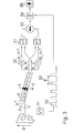
- an object 1 is moved relative to an image sensor 6 in the direction of the arrow 2 and its moving image 4 generated by an imaging lens 3 is moved into Direction of the arrow 5 is scanned by two sensor lines 7 and 8 of the camera not explicitly shown in the figure.
- the two single-line image sensor signals belonging to the same image line are further processed overlaid with a suitable mathematical processing module, for example by addition or averaging. This produces an output signal having a higher dynamic range or signal-to-noise ratio than each of the single-row signals. For this, however, the knowledge of the direction of movement 5 of the image is required.
- the direction of movement is determined as follows:
- the two image signal vectors of the sensor lines 7 and 8, a_n and b_n are each delayed by one line with a delaying memory element 20, whereby the delayed signal a_n-1 or b_n-1 can be compared with the current signal of the opposite line b_n or a_n in a respective comparison unit 21.
- This comparison can be purely logical.
- a measure of the equality is determined by a suitable mathematical method, in this case by means of the Euclidean distance of the image value vectors or by means of the image value vector distance according to another standard.
- the comparison can also be made on the basis of a correlation sum of the two image value vectors.
- the direction of movement 23 is finally determined. This detection of the direction of motion is based on the fact that the image feed either the image contents of a_n and b_n-1 or otherwise those of b_n and a_n-1 must be identical, depending on the direction of movement of the object 1. Identical image content but mean a high degree of equality or Similarity.
- the method described with reference to FIG. 2 then leads to a robust result when the image has a sufficient contrast in direction 5 of the relative movement.
- the arrangement shown in Fig. 3 is used.
- the equality values of the two comparison units 21 are combined in a further comparison unit 50, which in the case of the embodiment described here consists of a difference former, that information about the direction, in the example shown here, the sign the difference, and the significance, in the example shown here, the amount of the difference exists.
- This information is subsequently supplied to a state estimator 54, which generates a stable output signal 55 using a suitable mathematical method, as in this case by a linear state estimation, for example with a Kalman filter.
- the signal with respect to the speed of the relative movement 2 of the object 1 can be evaluated, with an appropriate measuring means 51, in the case of the embodiment described here an encoder, detected and sent to the camera in the form of a trigger signal 52 is transmitted.
- an appropriate measuring means 51 in the case of the embodiment described here an encoder, detected and sent to the camera in the form of a trigger signal 52 is transmitted.
- either the period duration 53 or the frequency of the trigger signal can be determined and the result of the state estimation unit 54 can be supplied.
- the reversal of the direction 2 is associated with an acceleration and a zero crossing of the speed, which is characterized by a high period duration 53 or by a low trigger pulse frequency.
- the state estimation unit 54 can better recognize the time of possible direction reversal, e.g. by a threshold comparison, and thus provide a very reliable output signal 55.
Landscapes
- Engineering & Computer Science (AREA)
- Multimedia (AREA)
- Signal Processing (AREA)
- Studio Devices (AREA)
- Image Analysis (AREA)
- Transforming Light Signals Into Electric Signals (AREA)
- Length Measuring Devices By Optical Means (AREA)
Applications Claiming Priority (3)
| Application Number | Priority Date | Filing Date | Title |
|---|---|---|---|
| DE102006052440 | 2006-11-03 | ||
| DE102007001760 | 2007-01-08 | ||
| DE102007015320A DE102007015320B4 (de) | 2006-11-03 | 2007-03-30 | Kamera zur Analyse von Objekten |
Publications (2)
| Publication Number | Publication Date |
|---|---|
| EP1919200A2 true EP1919200A2 (fr) | 2008-05-07 |
| EP1919200A3 EP1919200A3 (fr) | 2009-05-06 |
Family
ID=39102460
Family Applications (1)
| Application Number | Title | Priority Date | Filing Date |
|---|---|---|---|
| EP07019104A Withdrawn EP1919200A3 (fr) | 2006-11-03 | 2007-09-28 | Procédé et dispositif destinés à la reconnaissance automatique de la direction de déplacement relatif d'une caméra multilinéaire par rapport à l'objet |
Country Status (3)
| Country | Link |
|---|---|
| US (1) | US7755665B2 (fr) |
| EP (1) | EP1919200A3 (fr) |
| DE (1) | DE102007015320B4 (fr) |
Families Citing this family (2)
| Publication number | Priority date | Publication date | Assignee | Title |
|---|---|---|---|---|
| EP2150039A1 (fr) | 2008-07-28 | 2010-02-03 | Basler AG | Procédé de saisie d'image d'objets relativement mobiles |
| DE102020125235A1 (de) | 2020-09-28 | 2022-03-31 | Basler Aktiengesellschaft | Kamera und Spektrophotometer |
Family Cites Families (8)
| Publication number | Priority date | Publication date | Assignee | Title |
|---|---|---|---|---|
| DE59008311D1 (de) * | 1990-03-09 | 1995-03-02 | Itt Ind Gmbh Deutsche | Verfahren und Vorrichtung zur Reduktion des Kantenflackerns eines Fernsehbildes. |
| JP2991833B2 (ja) * | 1991-10-11 | 1999-12-20 | 松下電器産業株式会社 | インターレス走査ディジタルビデオ信号の符号化装置及びその方法 |
| CA2291691A1 (fr) * | 1997-05-29 | 1998-12-03 | Core Corp. | Dispositif de comptage d'une population de poissons passant a travers une passe a poissons |
| US6014182A (en) * | 1997-10-10 | 2000-01-11 | Faroudja Laboratories, Inc. | Film source video detection |
| US6940557B2 (en) * | 2001-02-08 | 2005-09-06 | Micronas Semiconductors, Inc. | Adaptive interlace-to-progressive scan conversion algorithm |
| US20030115490A1 (en) * | 2001-07-12 | 2003-06-19 | Russo Anthony P. | Secure network and networked devices using biometrics |
| US20050226489A1 (en) * | 2004-03-04 | 2005-10-13 | Glenn Beach | Machine vision system for identifying and sorting projectiles and other objects |
| US7558405B2 (en) * | 2005-06-30 | 2009-07-07 | Nokia Corporation | Motion filtering for video stabilization |
-
2007
- 2007-03-30 DE DE102007015320A patent/DE102007015320B4/de not_active Expired - Fee Related
- 2007-09-28 EP EP07019104A patent/EP1919200A3/fr not_active Withdrawn
- 2007-10-31 US US11/982,215 patent/US7755665B2/en not_active Expired - Fee Related
Also Published As
| Publication number | Publication date |
|---|---|
| US20080106618A1 (en) | 2008-05-08 |
| DE102007015320B4 (de) | 2008-10-23 |
| US7755665B2 (en) | 2010-07-13 |
| DE102007015320A1 (de) | 2008-05-08 |
| EP1919200A3 (fr) | 2009-05-06 |
Similar Documents
| Publication | Publication Date | Title |
|---|---|---|
| DE102010062496B4 (de) | Verfahren und Vorrichtung zum Verarbeiten von Bildinformationen zweier zur Bilderfassung geeigneter Sensoren eines Stereo-Sensor-Systems | |
| EP1330132B1 (fr) | Méthode et dispositif de détection d'occlusions dans des systèmes de capteurs d'images | |
| DE2703158A1 (de) | Einrichtung zum erkennen einer zeichenposition | |
| DE2545753A1 (de) | Anordnung zur erkennung aehnlicher objekte | |
| DE2643810A1 (de) | Verfahren zum einjustieren | |
| DE102019103963A1 (de) | Ildgebungsvorrichtung | |
| DE3829733C2 (fr) | ||
| DE69531510T2 (de) | Verfahren und Vorrichtung zur Bewegungsschätzung mittels Blockübereinstimmung | |
| DE112018007442B4 (de) | Datensynchronisationsvorrichtung, datensynchronisationsverfahren und datensynchronisationsprogramm | |
| EP0414113A2 (fr) | Procédé pour la compensation de mouvement dans un codeur ou un décodeur des images mouvantes | |
| DE102007015320B4 (de) | Kamera zur Analyse von Objekten | |
| DE4319343A1 (de) | Verfahren zur Bestimmung des Rauschanteils in einem Videosignal | |
| DE10210926A1 (de) | Vorrichtung zur Verfolgung wenigstens eines Objekts in einer Szene | |
| DE102021106988A1 (de) | Verfahren und System zur Bestimmung von Eigenbewegungsinformationen eines Fahrzeugs | |
| DE3440473C2 (fr) | ||
| EP0733293B2 (fr) | Procede de determination du niveau de bruit et detecteur du niveau de bruit | |
| EP2060109A1 (fr) | Procédé et dispositif pour la détection de pixels défectueux d'un capteur d'image, de préférence dans un système d'assistance de conducteur | |
| DE102019113647A1 (de) | Kamerasystem zur Erfassung von Objekten und/oder Objekteigenschaften | |
| DE102017221381A1 (de) | Verfahren, Vorrichtung und Computerprogramm zum Ermitteln eines Abstandes zu einem Objekt | |
| DE4409283C2 (de) | Verfahren und Schaltungsanordnung zur Beseitigung von Impulsstörungen | |
| EP2194510A2 (fr) | Système d'enregistrement de données | |
| DE102021209296B4 (de) | Verfahren zum Bestimmen der Bewegung eines mit wenigstens einer Videokamera zur Bilderfassung ausgestatteten Objekts | |
| EP3798969A1 (fr) | Procédé de traitement des images de profondeur, dispositif de traitement d'images et caméra à profondeur | |
| EP4531412B1 (fr) | Capture de flux d'objets à l'aide d'un capteur d'image basé sur des événements | |
| DE102010006522A1 (de) | Verfahren zur Analyse von korrespondierenden Bildpunkten in Bilddatensätzen |
Legal Events
| Date | Code | Title | Description |
|---|---|---|---|
| PUAI | Public reference made under article 153(3) epc to a published international application that has entered the european phase |
Free format text: ORIGINAL CODE: 0009012 |
|
| AK | Designated contracting states |
Kind code of ref document: A2 Designated state(s): AT BE BG CH CY CZ DE DK EE ES FI FR GB GR HU IE IS IT LI LT LU LV MC MT NL PL PT RO SE SI SK TR |
|
| AX | Request for extension of the european patent |
Extension state: AL BA HR MK RS |
|
| PUAL | Search report despatched |
Free format text: ORIGINAL CODE: 0009013 |
|
| AK | Designated contracting states |
Kind code of ref document: A3 Designated state(s): AT BE BG CH CY CZ DE DK EE ES FI FR GB GR HU IE IS IT LI LT LU LV MC MT NL PL PT RO SE SI SK TR |
|
| AX | Request for extension of the european patent |
Extension state: AL BA HR MK RS |
|
| 17P | Request for examination filed |
Effective date: 20090907 |
|
| AKX | Designation fees paid |
Designated state(s): AT BE BG CH CY CZ DE DK EE ES FI FR GB GR HU IE IS IT LI LT LU LV MC MT NL PL PT RO SE SI SK TR |
|
| STAA | Information on the status of an ep patent application or granted ep patent |
Free format text: STATUS: THE APPLICATION IS DEEMED TO BE WITHDRAWN |
|
| 18D | Application deemed to be withdrawn |
Effective date: 20130403 |