EP1919314B1 - Schutzhandschuh aus einem metallringgeflecht - Google Patents
Schutzhandschuh aus einem metallringgeflecht Download PDFInfo
- Publication number
- EP1919314B1 EP1919314B1 EP06776174A EP06776174A EP1919314B1 EP 1919314 B1 EP1919314 B1 EP 1919314B1 EP 06776174 A EP06776174 A EP 06776174A EP 06776174 A EP06776174 A EP 06776174A EP 1919314 B1 EP1919314 B1 EP 1919314B1
- Authority
- EP
- European Patent Office
- Prior art keywords
- protective glove
- glove according
- fastening strap
- limit stop
- loops
- Prior art date
- Legal status (The legal status is an assumption and is not a legal conclusion. Google has not performed a legal analysis and makes no representation as to the accuracy of the status listed.)
- Active
Links
Images




Classifications
-
- A—HUMAN NECESSITIES
- A41—WEARING APPAREL
- A41D—OUTERWEAR; PROTECTIVE GARMENTS; ACCESSORIES
- A41D19/00—Gloves
- A41D19/015—Protective gloves
- A41D19/01505—Protective gloves resistant to mechanical aggressions, e.g. cutting. piercing
- A41D19/01511—Protective gloves resistant to mechanical aggressions, e.g. cutting. piercing made of wire-mesh, e.g. butchers' gloves
-
- A—HUMAN NECESSITIES
- A41—WEARING APPAREL
- A41F—GARMENT FASTENINGS; SUSPENDERS
- A41F1/00—Fastening devices specially adapted for garments
- A41F1/06—Glove fasteners
Definitions
- the invention relates to a protective glove having the features specified in the preamble of claim 1.
- a protective glove is by the FR 2 836 790 A1 and become known through use.
- the well-known protective glove has on the wrist on the metal ring mesh loops, which are also formed from the metal ring mesh. Through the loops, a closing band is pulled out of a Polyerterkautschuk.
- This closing strap is equipped with a clasp consisting of a push button and a push button buckle.
- the push button buckle is adjustably attached to one end of the closing strap.
- the push button is bolted to the other end of the closing strap with this.
- a stamped and bent part made of sheet metal is anchored to the closing strip, which has a threaded part which engages in a hole of the closing strip.
- the push button is first unscrewed from the stamped and bent part. Then, the closing tape is threaded into the loops with the end in which the punching-bending part is located.
- a hole is provided through which the threaded portion of the screw fits through, with which the push button is to be fastened. Under this hole, the punching-bending part is positioned with its threaded part.
- the push button is placed on the outside of the metal ring mesh and the screw inserted through the push button and through the hole in the metal ring mesh in the threaded portion of the punching and bending part and screwed therein.
- the push button and the one end of the closing strap are fixed in a predetermined position on the glove.
- the known gloves are also available with a cuff made of metal ring mesh.
- two such closing straps are provided, one at the wrist and one at the rear end of the cuff.
- the known glove is disadvantageous that three metallic components are required for attaching the push button on the closing strap, namely the push button itself, a screw and a complicated punching and bending part with integrated threaded part, and all these parts made of hygienic stainless steel, because such gloves especially used in the meat processing industry.
- the way the locking strap is to be mounted by the user is annoying for the user.
- it is unavoidable for the user to change the closing strap from time to time, because it is a wear part and it does not tolerate every cleaning process that the metal ring mesh endures, which mostly consists of a stainless steel, sometimes titanium ,
- the push button and the screw will be lost. You could also accidentally get lost if the screw is not tightened enough when changing the locking strap. Lost metal parts in meat products must not occur.
- the present invention has for its object to improve a glove of the type mentioned in that its closing band less is complicated to manufacture and change and the risk of losing parts of the clasp is reduced.
- the protective glove according to the invention consists of a metal ring mesh, has a closing strap, which is captively but interchangeably held in loops, which are formed from the metal ring mesh and provided in the region of the wrist, and has a closure provided on the closing band.
- the locking band has at its rear end a different from the clasp stop member, which can not be pulled through the loop by the fact that it forms a positive engagement with the edge of a loop.
- the clasp itself can be matched in their dimensions to the clear width of the loops that they can be pushed through the loops.
- the clasp is preferably adjustable in order to adjust the width of the closed closing strap on different thickness wrists, you can also remove the adjustable part of the clasp from the closing strap, before inserting the locking strap in the loops or pulls out again, so that the removable Locking part does not bother even if it should be too big to be able to pull it through the loops.
- the positive engagement between the abutment part of the closing band and the edge of one of the loops of the metal ring mesh is preferably produced in that the stop member is so much wider and / or thicker than the closing band, that it can not be pulled through the loops.
- a trained locking band can be inexpensively made of a plastic, in particular of a thermoplastic material, which allows to form the locking band inexpensively in one piece by injection molding, so that the locking band is a molded part, which the stop member is integrally formed.
- a closing band of a thermoplastic elastomer in particular of a thermoplastic polyurethane.
- a closing band combines a whole series of advantages:
- the closing strap has optimum tensile strength, tear resistance and resistance to tearing and cuts.
- the closing strap has an extremely long service life with consistent characteristics.
- the locking band is food safe, resistant to almost all chemicals that are used in practice and resistant to hydrolysis.
- the closing strap is resistant to the temperatures which occur in practical use and in conventional cleaning processes.
- the closing strap is hygienic and easy to clean. The closing strap is easily interchangeable without the aid of tools.
- the adjustable and removable part of the clasp is preferably form-fitting fixable on the closing strap.
- the closing strap preferably has a corrugation, in particular ribs, which run transversely to the longitudinal direction of the closing strap and form a positive engagement with the removable part of the clasp.
- the removable part of the clasp is preferably a buckle, through which the closing strap is pulled with two deflections.
- Particularly suitable as a clasp is a push button clasp, consisting of a removable, adjustable along the closing strap snap fastener buckle and a push button, which is best arranged in the vicinity of the stop member.
- the push button can be permanently connected to the closing strap. It is particularly favorable to rivet him with the closing strap.
- a push button usually has a rounded contour. He can therefore easily push through the straps of the metal ring mesh with the locking band or, pull it.
- the closing band preferably has a reinforced head part, in particular one which is wedge-shaped in longitudinal section and has a width decreasing towards the tip, but is not wider than the subsequent closing strap. This facilitates the advancement and retraction of the locking band in the loops of the metal ring mesh.
- the stop member is preferably wider and thicker than the closing strip adjoining the stop member, in particular while forming a step between the stop member and the subsequent closing band. This facilitates the positive abutment of the stop member at the edge of a loop. Such a step is already effective if it is provided only on one side, because they can also strike only with the shoulder on one side of the tape at the edge of the loop.
- the step is provided on both sides of the closing strap so as not to have to pay attention to the orientation in which the closing strap is inserted when the closing strap is inserted into the loops.
- the stop part of the closing band is in any case as well as the push button outside the loops. It is therefore particularly suitable as an information carrier, which advantageously carries a label and / or marking, z. As a manufacturer, a size, a care or the like.
- the invention is suitable not only for protective gloves, which end at the wrist, but also for protective gloves with a cuff made of metal ring mesh.
- Such protective gloves with cuff in addition to a closure band according to the invention on the wrist preferably also a similarly formed locking strap in loops of the metal ring mesh, which are provided at the rear edge of the cuff.
- the slot allows adaptation to different thickness wrists and forearms.
- a loop adjoins both edges of the slot.
- the closing strap is threaded into the loops, that the stop member is in the slot, so that the slot is bridged by the closing band only by the closing operation.
- adjacent to the slot braid sections may overlap if necessary.
- the push button When closing the closing strap, you can pull on it without the risk of it sliding out of the loops. This prevents the stopper part.
- Against unintentional withdrawal in the opposite direction of the preferably provided push button provides a barrier by abutting the edge of the loop.
- the push button is formed so high that it does not easily slide into the loop. It also contributes to a provided on the push button waist, which can catch the edge of the loop.
- At least one of the two loops adjoining the slot in the glove is only a little shorter than the distance between the push button and the abutment part of the closing band, so that it has at most a small margin to slide back and forth in this loop.
- This dimensioning helps to secure the locking strap in the loop.
- both loops that define the slot the same length. This makes it possible to make a glove for the right hand fit for the left hand by turning it. In this case, the closing band can be turned.
- FIGS. 1 and 2 show a glove 1 with cuff 2, which consists of the fingertips to the rear edge of the cuff 2 of a metal ring mesh.
- the structure of such a metal ring mesh is z. B. from the DE 44 16 389 A1 known.
- a plurality of loops 4 made of metal ring mesh are provided in the area of the wrist 3 .
- more loops 5 are also provided metal ring mesh.
- pockets 6 are formed by that elongated strips of the metal ring mesh lie on the underlying metal ring mesh of the cuff 2 and are chained around with this.
- a strip of a thin spring plate which stiffens the cuff and prevents it from collapsing in the longitudinal direction of the arm.
- Another possibility is to first separately produce the actual glove and his cuff, to provide the cuff at its front edge with extensions of metal ring mesh to push these extensions of the cuff 2 over the end of the metal ring mesh of the actual glove and the front edges of the extensions to concatenate the cuff 2 with the metal ring mesh of the glove and to concatenate the rear edge of the metal ring mesh of the glove with the cuff 2.
- the extensions of the cuff 2 lie on the underlying metal ring mesh of the glove and thereby form the loops. 4
- Both the loops 4 in the region of the wrist 3 and the loops 5 at the rear end of the cuff 2 each receive a closing strap 7. This is in detail in the FIGS. 3 and 4 shown.
- the closing strip 7 is a flat plastic strip, in particular made of a thermoplastic elastomer, which is molded in one piece by injection molding.
- a head part 8 which is thicker than the closing strap 7 behind it, wherein on both sides a step 9 is formed between the head part 8 and the underlying closing strap 7, from which the head part 8 tapers in a wedge shape to a thickness that is about the thickness matches that has the lock strap behind the head part 8.
- the head part 8 has a semicircular edge 10.
- the closure band 7 is integrally formed on one side with a number of equidistant ribs 11, which are located only on one side of the closing band and transverse to the longitudinal direction of the closing band 7 extend.
- a termination piece 12 is formed, which is thicker than the preceding closing strap 7 and also thicker than the head part 8.
- a step 13 is formed on both sides. Starting from this stage 13, the stop member 12 tapers in a wedge shape to a thickness which is greater than the thickness of the closing band 7 in front of the stop member 12.
- the width of the closing strap 7 is adapted to the clear width of the loops 4 and 5.
- the stop member 12 is clearly over the narrow sides of the closing strap 7 and therefore can not be drawn into the loops 4 or 5.
- a push button 14 is riveted into the closing strap 7.
- the distance between the step 13 and the push button 14 is greater than the measured in the circumferential direction of the arm length of the loop 4 or 5, at the edge of the stop member 12 should strike.
- the closing strap 7 is inserted with the head part 8 first as the first, then in the remaining in the circumferential direction of the arm following loops 4 and 5.
- a snap fastener buckle 15 is pushed she in the FIGS. 5 to 7 is shown.
- the push-button buckle 15 is a stamped-bent part with a bottom 16, with four laterally bent tabs 17, which guide the narrow sides of the closing strap 7.
- a hole 18 is punched out and the edge of the hole 18 bent approximately conically out of the bottom 16. With the edge of the hole 18, the snap fastener buckle 15 is locked on the push button 14.
- the closing strap 7 can, as in FIG. 8 shown, are modified to the effect that the stop member 12, the closing strap 7 does not complete, but that the closing strap 7 is continued with a projection 7a on the stop member 12 addition.
- the push button can be arranged closer to the stopper 12 than in the first embodiment.
- FIG. 10 shows a section of a protective glove, which has a longitudinal slot 21 in the region of the wrist, to which two loops 4a and 4b adjoin. At the slot-side edge of the loop 4 b, the stop member 12 of the closing strap 7 strikes. From the other loop 4a protrudes the other end of the closing strap 7 with the snap fastener buckle 15 out.
Landscapes
- Engineering & Computer Science (AREA)
- Textile Engineering (AREA)
- Gloves (AREA)
- Professional, Industrial, Or Sporting Protective Garments (AREA)
Description
- Die Erfindung geht aus von einem Schutzhandschuh mit den im Oberbegriff des Anspruchs 1 angegebenen Merkmalen. Ein solcher Schutzhandschuh ist durch die
FR 2 836 790 A1 - Die bekannten Handschuhe gibt es auch mit einer Stulpe aus dem Metallringgeflecht. In diesem Fall sind zwei solche Schließbänder vorgesehen, eines am Handgelenk und eines am hinteren Ende der Stulpe.
- Bei dem bekannten Handschuh ist nachteilig, dass zum Anbringen des Druckknopfes am Schließband drei metallische Bauteile benötigt werden, nämlich der Druckknopf selbst, eine Schraube und ein kompliziertes Stanz-Biege-Teil mit integriertem Gewindeteil, und alle diese Teile aus hygienischem Edelstahl, weil solche Handschuhe vor allem im Fleisch verarbeitenden Gewerbe benutzt werden. Hinzu kommt, dass die Art und Weise, wie das Schließband vom Anwender zu montieren ist, für den Anwender lästig ist. Praktisch lässt es sich für den Anwender nicht vermeiden, das Schließband von Zeit zu Zeit zu wechseln, denn es handelt sich dabei um ein Verschleißteil und es verträgt nicht jeden Reinigungsvorgang, welchen das Metallringgeflecht aushält, welches zumeist aus einem Edelstahl, manchmal auch aus Titan besteht. Beim Wechseln des Schließbandes besteht obendrein die Gefahr, dass der Druckknopf und die Schraube verloren gehen. Sie könnten auch schon mal versehentlich verloren gehen, wenn beim Wechseln des Schließbandes die Schraube nicht fest genug angezogen wird. Verloren gegangene Metallteile in Fleischwaren dürfen aber nicht vorkommen.
- Der vorliegenden Erfindung liegt die Aufgabe zugrunde, einen Handschuh der eingangs genannten Art dahingehend zu verbessern, dass sein Schließband weniger aufwendig herzustellen und zu wechseln ist und die Gefahr, Teile der Schließe zu verlieren verringert ist.
- Diese Aufgabe wird gelöst durch einen Schutzhandschuh mit den im Anspruch 1 angegebenen Merkmalen. Vorteilhafte Weiterbildungen der Erfindung sind Gegenstand der Unteransprüche.
- Der erfindungsgemäße Schutzhandschuh besteht aus einem Metallringgeflecht, hat ein Schließband, welches unverlierbar, aber auswechselbar in Schlaufen gehalten ist, die aus dem Metallringgeflecht gebildet und im Bereich des Handgelenkes vorgesehen sind, und hat eine am Schließband vorgesehene Schließe. Das Schließband hat an seinem hinteren Ende ein von der Schließe verschiedenes Anschlagteil, welches dadurch, dass es mit dem Rand einer Schlaufe einen Formschluß eingeht, nicht durch die Schlaufe hindurchgezogen werden kann. Das hat den Vorteil, dass das Schließband, mit dem vorderen Ende voran, welches dem Anschlagteil abgewandt ist, durch die Schlaufen hindurchgezogen werden kann, bis das Anschlagteil an dem Rand jener Schlaufe, in welche das Schließband zuerst eingefädelt wurde, anschlägt. Das Schließband kann danach sofort gespannt und geschlossen werden.
- Die Schließe selbst kann in ihren Abmessungen so auf die lichte Weite der Schlaufen abgestimmt sein, dass sie durch die Schlaufen hindurchgeschoben werden kann. Da die Schließe jedoch vorzugsweise verstellbar ist, um die Weite des geschlossenen Schließbandes an unterschiedlich dicke Handgelenke anpassen zu können, kann man das verstellbare Teil der Schließe auch vom Schließband abnehmen, bevor man das Schließband in die Schlaufen einführt oder wieder herauszieht, so dass das abnehmbare Schließteil dabei selbst dann nicht stört, wenn es zu groß sein sollte, um es durch die Schlaufen ziehen zu können.
- Dadurch, dass das Schließband durch ein formschlüssiges Zusammenwirken des Anschlagteils mit dem Rand einer Schlaufe daran gehindert wird, durch die Schlaufe hindurch gezogen zu werden, ist das im Stand der Technik bekannte Verschrauben des Schließbandes mit dem Metallringgeflecht überflüssig. Damit entfällt auch die im Stand der Technik benötigte Schraube und es entfällt auch das im Stand der Technik benötigte, mit einem Gewindeabschnitt versehene Stanz-Biege-Teil, und schließlich entfällt auch ein besonderes Loch im Metallringgeflecht, welches im Stand der Technik benötigt wurde, um die Schraube hindurchzuführen. Herstellung, Montage und Auswechseln des Schließbandes sind deshalb gegenüber dem Stand der Technik stark vereinfacht.
- Der Formschluß zwischen dem Anschlagteil des Schließbandes und dem Rand einer der Schlaufen des Metallringgeflechtes wird vorzugsweise dadurch hergestellt, dass das Anschlagteil um soviel breiter und/oder dicker ist als das Schließband, dass es nicht durch die Schlaufen hindurchgezogen werden kann. Ein so ausgebildetes Schließband läßt sich preiswert aus einem Kunststoff herstellen, insbesondere aus einem thermoplastischen Kunststoff, welcher es erlaubt, das Schließband preiswert in einem Stück durch Spritzgießen zu formen, so dass das Schließband ein Formteil ist, welchem das Anschlagteil einstückig angeformt ist.
- Besonders geeignet ist ein Schließband aus einem thermoplastischen Elastomer, insbesondere aus einem thermoplastischen Polyurethan. Ein solches Schließband vereinigt eine ganze Reihe von Vorteilen:
- Es ist weich, anschmiegsam und bietet höchsten Tragekomfort ohne Druckstellen.
Das Schließband hat eine optimale Zugfestigkeit, Reißfestigkeit und Widerstandsfähigkeit gegen ein Weiterreissen bei Schnitten und anderen Beschädigungen.
Das Schließband hat eine extrem lange Lebensdauer bei gleichbleibenden Eigenschaften.
Das Schließband ist lebensmittelecht, beständig gegen fast alle in der Praxis vorkommenden Chemikalien und hydrolysebeständig.
Das Schließband ist gegenüber den im praktischen Einsatz und in üblichen Reinigungsverfahren auftretenden Temperaturen beständig.
Das Schließband ist hygienisch und gut reinigbar.
Das Schließband ist ohne Zuhilfenahme von Werkzeugen leicht austauschbar. - Ist die Schließe verstellbar, dann ist der verstell- und abnehmbare Teil der Schließe vorzugsweise formschlüssig auf dem Schließband festlegbar. Zu diesem Zweck hat das Schließband in jenem Abschnitt, in welchem das abnehmbare Teil der Schließe festgelegt werden soll, vorzugsweise eine Riffelung, insbesondere Rippen, welche quer zur Längsrichtung des Schließbandes verlaufen und einen Formschluß mit dem abnehmbaren Teil der Schließe eingehen. Das abnehmbare Teil der Schließe ist vorzugsweise eine Schnalle, durch welche das Schließband unter zweifachem Umlenken hindurchgezogen wird. Besonders geeignet als Schließe ist eine Druckknopfschließe, bestehend aus einer abnehmbaren, längs des Schließbandes verstellbaren Druckknopfschnalle und einem Druckknopf, welcher am besten in der Nachbarschaft des Anschlagteils angeordnet ist. Der Druckknopf kann unlösbar mit dem Schließband verbunden sein. Besonders günstig ist es, ihn mit dem Schließband zu vernieten. Ein Druckknopf hat üblicherweise eine gerundete Kontur. Er läßt sich deshalb mit dem Schließband leicht durch die Schlaufen des Metallringgeflechts hindurchschieben bzw., hindurchziehen.
- Um das Durchschieben des Schließbandes durch die Schlaufen zu erleichtern, hat das Schließband vorzugsweise ein verstärktes Kopfteil, insbesondere ein solches, welches im Längsschnitt keilförmig ausgebildet ist und eine zur Spitze hin abnehmende Breite hat, aber nicht breiter ist als das anschließende Schließband. Das erleichtert das Vorschieben und Zurückziehen des Schließbandes in den Schlaufen des Metallringgeflechts.
- Das Anschlagteil ist vorzugsweise breiter und dicker als das an das Anschlagteil anschließende Schließband, insbesondere unter Ausbilden einer Stufe zwischen dem Anschlagteil und dem anschließenden Schließband. Das erleichtert das formschlüssige Anschlagen des Anschlagteils am Rand einer Schlaufe. Eine solche Stufe ist bereits dann wirksam, wenn sie nur einseitig vorgesehen ist, weil sie auch nur mit der Schulter auf einer Seite des Bandes am Rand der Schlaufe anschlagen kann.
- Vorzugsweise ist die Stufe jedoch zu beiden Seiten des Schließbandes vorgesehen, um beim Einführen des Schließbandes in die Schlaufen nicht darauf achten zu müssen, in welcher Orientierung das Schließband eingeführt wird.
- Das Anschlagteil des Schließbandes liegt jedenfalls ebenso wie der Druckknopf außerhalb der Schlaufen. Es eignet sich deshalb besonders als Informationsträger, der mit Vorteil eine Beschriftung und/oder Kennzeichnung trägt, z. B. eine Herstellerangabe, eine Größenangabe, einen Pflegehinweis oder dergleichen.
- Die Erfindung eignet sich nicht nur für Schutzhandschuhe, welche am Handgelenk enden, sondern auch für Schutzhandschuhe mit einer Stulpe aus dem Metallringgeflecht. Solche Schutzhandschuhe mit Stulpe haben außer einem erfindungsgemäßen Schließband am Handgelenk vorzugsweise auch ein gleichartig ausgebildetes Schließband in Schlaufen aus dem Metallringgeflecht, welche am hinteren Rand der Stulpe vorgesehen sind.
- Das Anziehen des Handschuhs wird erleichtert, wenn dieser im Bereich des Handgelenkes und - wenn eine Stulpe vorhanden ist - auch im Bereich des hinteren Endes der Stulpe einen Längsschlitz im Metallringgewebe hat.
- Der Schlitz erlaubt eine Anpassung an unterschiedlich dicke Handgelenke bzw. Unterarme. Vorzugsweise grenzt an beide Ränder des Schlitzes jeweils eine Schlaufe an. Zweckmäßigerweise wird das Schließband so in die Schlaufen eingefädelt, dass das Anschlagteil im Schlitz liegt, so dass der Schlitz erst durch den Schließvorgang vom Schließband überbrückt wird. Dabei können sich die an den Schlitz angrenzenden Geflechtsabschnitte erforderlichenfalls überlappen.
- Beim Schließen des Schließbandes kann man an diesem ziehen, ohne dass die Gefahr besteht, dass es aus den Schlaufen herausgleitet. Das verhindert das Anschlagteil. Gegen unabsichtliches Herausziehen in der Gegenrichtung bietet der vorzugsweise vorgesehene Druckknopf eine Barriere, indem er am Rand der Schlaufe anstößt. Zweckmäßigerweise wird der Druckknopf so hoch ausgebildet, dass er nicht leicht in die Schlaufe hineingleitet. Dazu trägt auch eine am Druckknopf vorgesehene Taille bei, welche den Rand der Schlaufe fangen kann.
- Vorzugsweise ist wenigstens eine der beiden Schlaufen, die an den Schlitz im Handschuh angrenzt, nur wenig kürzer als der Abstand zwischen dem Druckknopf und dem Anschlagteil des Schließbandes, so dass dieses einen allenfalls geringen Spielraum hat, um in dieser Schlaufe hin und her zu rutschen. Diese Bemessung trägt zur Sicherung des Schließbandes in der Schlaufe bei. Vorzugsweise sind beide Schlaufen, die den Schlitz begrenzen, gleich lang ausgebildet. Das macht es möglich, einen Handschuh für die rechte Hand dadurch für die linke Hand passend zu machen, dass er gewendet wird. Für diesen Fall kann auch das Schließband gewendet werden.
- Gleiche oder einander entsprechende Teile sind in den Beispielen mit übereinstimmenden Bezugszahlen bezeichnet. Ausführungsbeispiele der Erfindung sind in den beigefügten Abbildungen dargestellt.
- Figur 1
- zeigt einen erfindungsgemäßen Handschuh mit Stulpe in einer Ansicht auf die Rückseite der Hand,
- Figur 2
- zeigt den Handschuh aus
Figur 1 in einer Ansicht auf die Vorderseite der Hand, - Figur 3
- zeigt ein Schließband für den Handschuh in einer Draufsicht,
- Figur 4
- zeigt das Schließband aus
Figur 3 in einer Seitenansicht, - Figur 5
- zeigt eine Druckknopfschnalle für das Schließband in einer Ansicht auf die Unterseite,
- Figur 6
- zeigt die Druckknopfschnalle aus
Figur 5 in einer ersten Seitenansicht, - Figur 7
- zeigt die Druckknopfschnalle aus
Figur 5 in einer zweiten Seitenansicht, - Figur 8
- zeigt in einer Darstellung wie in
Figur 3 eine Abwandlung des Schließbandes, - Figur 9
- zeigt das Schließband aus
Figur 8 in einer Ansicht wie inFigur 4 , und - Figur 10
- zeigt einen Abschnitt eines Schutzhandschuhs im Bereich seines Schlitzes.
- Die
Figuren 1 und2 zeigen einen Handschuh 1 mit Stulpe 2, welcher von den Fingerspitzen bis zum hinteren Rand der Stulpe 2 aus einem Metallringgeflecht besteht. Der Aufbau eines solchen Metallringgeflechtes ist z. B. aus derDE 44 16 389 A1 bekannt. Im Bereich des Handgelenkes 3 sind mehrere Schlaufen 4 aus Metallringgeflecht vorgesehen. Am hinteren Ende der Stulpe 2 sind ebenfalls mehrere Schlaufen 5 aus Metallringgeflecht vorgesehen. Im dargestellten Beispiel sind es jeweils drei Schlaufen 4, 5, welche sich am hinteren Ende der Stulpe 2 in Anpassung an den größeren Umfang des Unterarms in Umfangsrichtung über eine größere Strecke erstrecken als im Bereich des Handgelenks 3. - Zwischen den Schlaufen 4 am Handgelenk 3 und den hinteren Schlaufen 5 sind mehrere in Längsrichtung des Arms verlaufende Taschen 6 dadurch gebildet sind, dass längliche Streifen aus dem Metallringgeflecht auf dem darunterliegenden Metallringgeflecht der Stulpe 2 liegen und ringsum mit diesem verkettet sind. In diesen Taschen 6 befindet sich jeweils ein Streifen aus einem dünnen Federblech, welcher die Stulpe versteift und verhindert, dass sie in Längsrichtung des Arms zusammenfällt.
- Zur Bildung der Schlaufen im Bereich des Handgelenkes 3 gibt es unterschiedliche Möglichkeiten. Eine Möglichkeit besteht darin, dass man den eigentlichen Handschuh einlagig in die Stulpe 2 übergehen läßt und im Bereich des Handgelenks 3 lediglich einige um das Handgelenk herum verteilte Schlitze im Metallringgeflecht vorsieht, durch welche man ein Schließband 7 alternierend hindurchzieht.
- Eine andere Möglichkeit besteht darin, den eigentlichen Handschuh und seine Stulpe zunächst gesondert herzustellen, die Stulpe an ihrem vorderen Rand mit Fortsätzen aus Metallringgeflecht zu versehen, diese Fortsätze der Stulpe 2 über das Ende des Metallringgeflechts des eigentlichen Handschuhs zu schieben und die vorderen Ränder der Fortsätze der Stulpe 2 mit dem Metallringgeflecht des Handschuhs zu verketten und den hinteren Rand des Metallringgeflechtes des Handschuhs mit der Stulpe 2 zu verketten. In diesem Fall liegen die Fortsätze der Stulpe 2, auf dem darunterliegenden Metallringgeflecht des Handschuhs und bilden dadurch die Schlaufen 4.
- Eine weitere Möglichkeit, im Bereich des Handgelenks 3 Schlaufen 4 zu bilden, besteht darin, den Handschuh und seine Stulpe 2 zunächst einlagig ineinander übergehen zu lassen. Darauf legt man dann Streifen des Metallringgeflechts mit den Abmessungen der Schlaufen und verkettet ihre vorderen und hinteren Ränder mit dem darunter liegenden Metallringgeflecht. Am hinteren Rand der Stulpe 2 sind die Schlaufen 5 durch Fortsätze des Metallringgeflechts gebildet, deren hinterer Rand nach vorne umgeschlagen und mit dem Metallringgeflecht der Stulpe 2 verkettet worden ist. Auf die gleiche Weise kann man Schlaufen am Rand eines Handschuhs ohne Stulpe bilden.
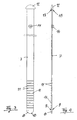
- Sowohl die Schlaufen 4 im Bereich des Handgelenks 3 als auch die Schlaufen 5 am hinteren Ende der Stulpe 2 nehmen jeweils ein Schließband 7 auf. Dieses ist im einzelnen in den
Figuren 3 und 4 dargestellt. - Das Schließband 7 ist ein flaches Kunststoffband, insbesondere aus einem thermoplastischen Elastomer, welches in einem Stück durch Spritzgießen geformt ist. Am vorderen Ende des Schließbandes 7 befindet sich ein Kopfteil 8, welches dicker ist als das dahinterliegende Schließband 7, wobei zwischen dem Kopfteil 8 und dem dahinterliegenden Schließband 7 beidseits eine Stufe 9 ausgebildet ist, von welcher aus sich das Kopfteil 8 keilförmig auf eine Dicke verjüngt, die ungefähr mit der Dicke übereinstimmt, die das Schließband hinter dem Kopfteil 8 hat. Außerdem hat das Kopfteil 8 einen halbkreisförmigen Rand 10. In einem Abschnitt, der an das Kopfteil 8 anschließt, ist dem Schließband 7 einseitig eine Anzahl von äquidistanten Rippen 11 angeformt, welche sich nur auf einer Seite des Schließbandes befinden und sich quer zur Längsrichtung des Schließbandes 7 erstrecken.
- Dem hinteren Ende des Schließbandes 7 ist ein Abschlußstück 12 angeformt, welches dicker ist als das davorliegende Schließband 7 und auch dicker ist als das Kopfteil 8. Am Übergang vom Anschlagteil 12 zu dem davor liegenden Abschnitt des Schließbandes 7 ist beidseitig eine Stufe 13 ausgebildet. Ausgehend von dieser Stufe 13 verjüngt sich das Anschlagteil 12 keilförmig auf eine Dicke, welche größer ist als die Dicke des Schließbandes 7 vor dem Anschlagteil 12.
- Die Breite des Schließbandes 7 ist der lichten Weite der Schlaufen 4 und 5 angepaßt. Das Anschlagteil 12 steht deutlich über die Schmalseiten des Schließbandes 7 über und kann deshalb nicht in die Schlaufen 4 oder 5 hineingezogen werden.
- In der Nachbarschaft des Anschlagteils 12 ist in das Schließband 7 ein Druckknopf 14 eingenietet. Der Abstand zwischen der Stufe 13 und dem Druckknopf 14 ist größer als die in Umfangsrichtung des Arms gemessene Länge der Schlaufe 4 oder 5, an deren Rand das Anschlagteil 12 anschlagen soll. In diese Schlaufe wird das Schließband 7 mit dem Kopfteil 8 voran als erstes eingeschoben, dann in die restlichen in Umfangsrichtung des Arms folgenden Schlaufen 4 bzw. 5. Anschließend wird auf den mit den Rippen 11 versehenen Abschnitt des Schließbandes 7 eine Druckknopfschnalle 15 geschoben, wie sie in den
Figuren 5 bis 7 dargestellt ist. Die Druckknopfschnalle 15 ist ein Stanz-Biege-Teil mit einem Boden 16, mit vier seitlich abgebogenen Laschen 17, welche die Schmalseiten des Schließbandes 7 führen. In der Mitte des Bodens 16 ist ein Loch 18 ausgestanzt und der Rand des Loches 18 annähernd konisch aus dem Boden 16 herausgebogen. Mit dem Rand des Loches 18 wird die Druckknopfschnalle 15, auf den Druckknopf 14 gerastet. - Zu beiden Seiten des Loches 18 erstreckt sich zwischen je zwei Laschen 17 ein Schlitz 19 bzw. 20. Durch diese Schlitze 19 und 20 wird das Schließband 7 mit dem Kopfteil 8 voran durchgezogen, zunächst von der Unterseite her durch den Schlitz 19 und dann von der Oberseite her durch den Schlitz 20. Die Kanten der Schlitze 19 und 20 führen in Zusammenarbeit mit den Rippen 11 zu einem formschlüssigen Eingriff, der um so intensiver wird, je stärker der Zug ist, der auf das Schließband 7 ausgeübt wird.
- Das Schließband 7 kann, wie in
Figur 8 dargestellt, dahingehend abgewandelt werden, dass das Anschlagteil 12 das Schließband 7 nicht abschließt, sondern dass das Schließband 7 mit einem Fortsatz 7a über das Anschlagteil 12 hinaus fortgesetzt ist. In diesem Fall kann der Druckknopf näher beim Anschlagteil 12 angeordnet werden als im ersten Ausführungsbeispiel. -
Figur 10 zeigt einen Ausschnitt eines Schutzhandschuhs, welcher im Bereich des Handgelenks einen längs verlaufenden Schlitz 21 hat, an welchen zwei Schlaufen 4a und 4b angrenzen. Am schlitzseitigen Rand der Schlaufe 4b schlägt das Anschlagteil 12 des Schließbandes 7 an. Aus der anderen Schlaufe 4a ragt das andere Ende des Schließbandes 7 mit der Druckknopfschnalle 15 heraus. -
- 1.
- Handschuh
- 2.
- Stulpe
- 3.
- Handgelenk
- 4.
- Schlaufe
- 4a.
- Schlaufe
- 4b.
- Schlaufe
- 5.
- Schlaufe
- 6.
- Tasche
- 7.
- Schließband
- 7a.
- Fortsatz
- 8.
- Kopfteil
- 9.
- Stufe
- 10.
- Rand
- 11.
- Rippen
- 12.
- Anschlagteil
- 13.
- Stufe
- 14.
- Druckknopf
- 15.
- Druckknopfschnalle
- 16.
- Boden
- 17.
- Laschen
- 18.
- Lochen
- 19.
- Schlitz
- 20.
- Schlitz
- 21.
- Schlitz
Claims (28)
- Schutzhandschuh aus einem Metallringgeflecht
mit einem Schließband (7), welches unverlierbar, aber auswechselbar in Schlaufen (4, 5) gehalten ist,
und mit einer am Schließband (7) vorgesehenen Schließe (14, 15),
dadurch gekennzeichnet, dass das Schließband (7) an seinem hinteren Ende ein von der Schließe (14, 15) verschiedenes Anschlagteil (12) aufweist, welches dadurch, dass es mit dem Rand einer Schlaufe (4, 5) einen Formschluß eingeht, nicht durch die Schlaufe (4, 5) hindurchgezogen werden kann. - Schutzhandschuh nach Anspruch 1, dadurch gekennzeichnet, dass das Anschlagteil (12) um soviel breiter und/oder dicker ist als das Schließband (7), dass es nicht durch die Schlaufen (4, 5) hindurchgezogen werden kann.
- Schutzhandschuh nach Anspruch 1 oder 2, bei welchem ein Teil (15) der Schließe (14, 15) so groß ist, dass er nicht mit dem Schließband (7) durch die Schlaufen (4, 5) geschoben werden kann, dadurch gekennzeichnet, dass dieser Teil (15) der Schließe abnehmbar am Schließband (7) gehalten ist.
- Schutzhandschuh nach Anspruch 3, dadurch gekennzeichnet, dass der abnehmbare Teil (15) der Schließe formschlüssig auf dem Schließband (7) festlegbar ist.
- Schutzhandschuh nach einem der vorstehenden Ansprüche, dadurch gekennzeichnet, dass die Schließe aus einem Druckknopf (14) und einer Druckknopfschnalle (15) besteht.
- Schutzhandschuh nach Anspruch 5, dadurch gekennzeichnet, dass der Druckknopf (14) in der Nachbarschaft des Anschlagteils (12) angeordnet ist.
- Schutzhandschuh nach Anspruch 5 oder 6, dadurch gekennzeichnet, dass der Druckknopf (14) mit dem Schließband (7) unlösbar verbunden, insbesondere vernietet ist.
- Schutzhandschuh nach einem der vorstehenden Ansprüche, dadurch gekennzeichnet, dass das Schließband (7) aus einem Kunststoff besteht.
- Schutzhandschuh nach Anspruch 8, dadurch gekennzeichnet, dass das Schließband (7) aus einem thermoplastischen Kunststoff besteht.
- Schutzhandschuh nach Anspruch 9, dadurch gekennzeichnet, dass das Schließband (7) aus einem thermoplastischen Elastomer, insbesondere aus einem thermoplastischen Polyurethan besteht.
- Schutzhandschuh nach einem der Ansprüche 8 bis 10, dadurch gekennzeichnet, dass das Schließband (7) ein Formteil ist, welchem das Anschlagteil (12) einstückig angeformt ist.
- Schutzhandschuh nach Anspruch 11, dadurch gekennzeichnet, dass das Schließband (7) für die Formschlußverbindung mit dem abnehmbaren Teil (15) der Schließe quer zur Längsrichtung des Schließbandes (7) verlaufende Rippen (11) aufweist.
- Schutzhandschuh nach einem der vorstehenden Ansprüche, dadurch gekennzeichnet, dass das Kopfteil (8) verglichen mit dem anschließenden Abschnitt des Schließbandes (7) verstärkt ist.
- Schutzhandschuh nach einem der vorstehenden Ansprüche, dadurch gekennzeichnet, dass das Anschlagteil (12) dicker ist als der anschließende Abschnitt des Schließbandes (7).
- Schutzhandschuh nach Anspruch 14, dadurch gekennzeichnet, dass zwischen dem Anschlagteil (12) und dem anschließenden Abschnitt des Schließbandes (7) eine Stufe (13) vorgesehen ist.
- Schutzhandschuh nach Anspruch 15, dadurch gekennzeichnet, dass die Stufe (13) beidseitig vorgesehen ist.
- Schutzhandschuh nach einem der Ansprüche 13 bis 16, dadurch gekennzeichnet, dass das Kopfteil (8) im Längsschnitt keilförmig ausgebildet ist.
- Schutzhandschuh nach einem der Ansprüche 13 bis 17, dadurch gekennzeichnet, dass die Breite des Kopfteils (8) zur Spitze hin abnimmt, insbesondere kreisbogenförmig abnimmt.
- Schutzhandschuh nach einem der vorstehenden Ansprüche, dadurch gekennzeichnet, dass das Anschlagteil (12) mit einer Beschriftung versehen ist.
- Schutzhandschuh nach einem der vorstehenden Ansprüche, dadurch gekennzeichnet, dass das Anschlagteil mit einer Kennzeichnung versehen ist.
- Schutzhandschuh nach einem der vorstehenden Ansprüchhe, dadurch gekennzeichnet, dass das Anschlagteil (12) das hintere Ende des Schließbandes (7) bildet.
- Schutzhandschuh nach einem der Ansprüche 1 bis 20, dadurch gekennzeichnet, dass an das Anschlagteil (12) ein Fortsatz (7a) des Schließbandes (7) anschließt, welcher dünner und schmäler als das Anschlagteil (12) ist und auf welchem ein Teil des Schließe (14, 15) verankert ist, insbesondere ein Druckknopf (14).
- Schutzhandschuh nach Anspruch 22, dadurch gekennzeichnet, dass der Fortsatz (7a) im Querschnitt übereinstimmt mit dem vor dem Anschlagteil (12) anschließenden Abschnitt des Schließbandes (7).
- Schutzhandschuh nach einem der vorstehenden Ansprüche, welcher eine Stulpe (2) aus dem Metallringgeflecht hat, dadurch gekennzeichnet, dass ein weiteres Schließband (7) derselben Art in Schlaufen (5) vorgesehen ist, welche aus Metallringgeflecht bestehen und am hinteren Ende der Stulpe (2) vorgesehen sind.
- Schutzhandschuh nach einem der vorstehenden Ansprüche, dadurch gekennzeichnet, dass das Metallringgeflecht im Bereich der Schlaufen (4, 5) einen längs verlaufenden Schlitz (21) hat.
- Schutzhandschuh nach Anspruch 25, dadurch gekennzeichnet, dass an beide Ränder des Schlitzes (21) eine Schlaufe (4a, 4b) angrenzt.
- Schutzhandschuh nach Anspruch 25 oder 26, dadurch gekennzeichnet, dass das Anschlagteil (12) im Schlitz (21) liegt.
- Schutzhandschuh nach Anspruch 5 und einem der Ansprüche 25 bis 27, dadurch gekennzeichnet, dass wenigstens eine der beiden am Schlitz (21) angeordneten Schlaufen (4a, 4b) nur wenig kürzer ist als der Abstand des Druckknopfs (14) vom Anschlagteil (12).
Priority Applications (1)
| Application Number | Priority Date | Filing Date | Title |
|---|---|---|---|
| PL06776174T PL1919314T3 (pl) | 2005-07-11 | 2006-07-11 | Rękawica ochronna z plecionki z metalowych pierścieni |
Applications Claiming Priority (2)
| Application Number | Priority Date | Filing Date | Title |
|---|---|---|---|
| DE202005011181U DE202005011181U1 (de) | 2005-07-11 | 2005-07-11 | Schutzhandschuh aus einem Metallringgeflecht |
| PCT/EP2006/006742 WO2007006538A1 (de) | 2005-07-11 | 2006-07-11 | Schutzhandschuh aus einem metallringgeflecht |
Publications (2)
| Publication Number | Publication Date |
|---|---|
| EP1919314A1 EP1919314A1 (de) | 2008-05-14 |
| EP1919314B1 true EP1919314B1 (de) | 2009-12-02 |
Family
ID=35140460
Family Applications (1)
| Application Number | Title | Priority Date | Filing Date |
|---|---|---|---|
| EP06776174A Active EP1919314B1 (de) | 2005-07-11 | 2006-07-11 | Schutzhandschuh aus einem metallringgeflecht |
Country Status (11)
| Country | Link |
|---|---|
| US (1) | US20090210992A1 (de) |
| EP (1) | EP1919314B1 (de) |
| AT (1) | ATE450164T1 (de) |
| AU (1) | AU2006268913B2 (de) |
| BR (1) | BRPI0612876A2 (de) |
| DE (2) | DE202005011181U1 (de) |
| ES (1) | ES2336704T3 (de) |
| NZ (1) | NZ565127A (de) |
| PL (1) | PL1919314T3 (de) |
| RU (1) | RU2369304C1 (de) |
| WO (1) | WO2007006538A1 (de) |
Cited By (1)
| Publication number | Priority date | Publication date | Assignee | Title |
|---|---|---|---|---|
| DE202012103421U1 (de) | 2012-09-07 | 2013-01-14 | Friedrich Münch GmbH & Co. KG | Schließband zur Befestigung an einer aus einem Metallringgeflecht gebildeten Schlaufe einer Schutzbekleidung und solch eine Schutzbekleidung |
Families Citing this family (13)
| Publication number | Priority date | Publication date | Assignee | Title |
|---|---|---|---|---|
| FR2899441B1 (fr) | 2006-04-10 | 2008-07-04 | Manulatex France Soc Par Actio | Article en cotte de mailles equipe d'un organe elastique de resserrement ou de mise en tension |
| FR2899440B1 (fr) * | 2006-04-10 | 2008-07-04 | Manulatex France Soc Par Actio | Gant de protection en cotte de mailles muni de moyens de mise en tension de la maille |
| DE102007004032B3 (de) | 2007-01-22 | 2008-10-02 | Ziegler Mechanische Werkstatt, Metallgewebe Und Arbeitsschutz Gmbh | Schutzhandschuh aus einem wendbaren Metallringgeflecht |
| DE102007038224A1 (de) | 2007-08-13 | 2009-02-26 | Ziegler Mechanische Werkstatt, Metallgewebe Und Arbeitsschutz Gmbh | Schutzbekleidung mit einem Befestigungsmittel |
| US10231497B2 (en) * | 2013-06-10 | 2019-03-19 | Voesh Corporation | Skin care mask glove and mask sock |
| USD745220S1 (en) * | 2014-06-20 | 2015-12-08 | Abel Unlimited Inc. | Mesh glove |
| US9924750B2 (en) * | 2014-07-23 | 2018-03-27 | Skate-Cut-Proof Inc. | Athletic protective shield |
| USD802221S1 (en) * | 2014-11-20 | 2017-11-07 | Us Mesh Llc | Cut resistant glove with elastomeric straps |
| US9936750B2 (en) * | 2015-09-18 | 2018-04-10 | Worldwide Protective Products, Llc | Protective garment with integrated metal mesh regions |
| GB2551467A (en) * | 2016-04-13 | 2017-12-27 | Knitmesh Ltd | Protective sleeve |
| USD1046375S1 (en) * | 2021-12-07 | 2024-10-15 | Changzhou Ansir Safety Product Co., Ltd | Glove |
| US12295434B2 (en) * | 2022-10-31 | 2025-05-13 | Jeffrey D. Heyd | Hand protection device and method of use |
| FR3168134A1 (fr) | 2024-11-04 | 2026-05-08 | Manulatex France | Article en tissu de cotte de maille comprenant un moyen de serrage et un organe renfort |
Family Cites Families (38)
| Publication number | Priority date | Publication date | Assignee | Title |
|---|---|---|---|---|
| US2513592A (en) * | 1946-06-29 | 1950-07-04 | Silverman Charles | Bracelet clasp |
| US3145442A (en) * | 1962-12-07 | 1964-08-25 | Brown Ray | Safety belt buckle |
| US3347547A (en) * | 1965-07-28 | 1967-10-17 | Lee P Hynes | Hand and finger exercising device |
| ES160552Y (es) * | 1968-03-30 | 1971-06-01 | Bremshey & Co. | Estuche con paraguas longitudinalmente acortable y con un lazo portador. |
| US3514816A (en) * | 1968-05-13 | 1970-06-02 | Toyota Motor Co Ltd | Pushbutton separable fastener |
| US3796461A (en) * | 1971-09-29 | 1974-03-12 | Robbins J Seat Belt Co | Quick disconnect seat belt tongue |
| FR2354724A1 (fr) * | 1976-06-02 | 1978-01-13 | Renault | Boucle de securite a fixation et a reglage rapide notamment pour casques de protection |
| DE2818021C2 (de) * | 1978-04-25 | 1980-01-17 | Friedrich Muench Silber- Und Alpaccawarenfabrik, 7130 Muehlacker | Dekoratives Metallgeflecht aus Metallplättchen für Handtaschen u.dgl |
| US4388733A (en) * | 1981-05-29 | 1983-06-21 | Maurice Anstett | Protective butchers glove |
| US4530350A (en) * | 1981-09-28 | 1985-07-23 | Brown Ronald E | Limb protective coverings |
| DE3238499C1 (de) * | 1982-10-18 | 1990-01-04 | Friedrich Münch GmbH & Co. KG, 7130 Mühlacker | Schutzhandschuh aus Metallringgeflecht und Verfahren zu seiner Herstellung |
| US4471495A (en) * | 1983-01-14 | 1984-09-18 | Whiting And Davis Company, Inc. | Protective glove |
| US4800595A (en) * | 1986-10-30 | 1989-01-31 | Askew Robert J | Circumferential suppression system |
| US4750218A (en) * | 1986-12-29 | 1988-06-14 | Azon Corporation | Reversible glove construction |
| US4843650A (en) * | 1988-01-11 | 1989-07-04 | Kangas Lawrence W | Protective glove |
| US4942626A (en) * | 1988-12-23 | 1990-07-24 | Medev Corporation | Needlestick protective glove |
| US5054126A (en) * | 1990-09-21 | 1991-10-08 | Saf-T-Gard International, Inc. | Reversible protective glove |
| US5088123A (en) * | 1991-05-10 | 1992-02-18 | Whiting And Davis Company, Inc. | Protective garment |
| GB2275174B (en) * | 1993-02-20 | 1996-05-22 | Paul Heilemann | Protective glove |
| AU2562595A (en) * | 1994-05-09 | 1995-11-29 | Friedrich Munch Gmbh & Co. Kg | Protective glove |
| NL9401704A (nl) * | 1994-10-14 | 1996-05-01 | Johannes Adrianus Augustinus V | Veiligheidshandschoen uit metalen ringen, voorzien van elastische sluitingen en gesloten pols- en arm-gedeelten. |
| US5511241A (en) * | 1994-11-14 | 1996-04-30 | Azon Corporation | Chain mail garments impregnated with an elastomeric material |
| US5704066A (en) * | 1996-09-27 | 1998-01-06 | Yamamoto; Paul Kiyoshi | Protective glove device |
| US5740555A (en) * | 1996-12-03 | 1998-04-21 | Renegar; Robert M. | Glove design for improved fit and utility |
| US5867832A (en) * | 1997-12-08 | 1999-02-09 | Liu; Fang Yi | Disposable vinyl glove having fastening belt |
| FR2775165B1 (fr) * | 1998-02-26 | 2000-04-28 | Foin Ets | Gant de protection en tissu de cotte de maille |
| FR2776482B1 (fr) * | 1998-03-27 | 2000-06-16 | Manulatex France | Perfectionnement aux gants en cotte de mailles |
| US5894602A (en) * | 1998-06-03 | 1999-04-20 | Wdc Holdings, Inc. | Protective glove |
| US6061833A (en) * | 1998-12-17 | 2000-05-16 | Wdc Holdings, Inc. | Protective glove with improved wrist strap |
| DE29901502U1 (de) * | 1999-01-29 | 1999-05-12 | Schlachthausfreund Fabrikations- u. Vertriebs-GmbH, 21256 Handeloh | Schutzhandschuh |
| US6470832B1 (en) * | 2000-02-16 | 2002-10-29 | Charlton Peacock | Animal boots |
| FR2813763B1 (fr) * | 2000-09-12 | 2003-01-24 | Manulatex | Perfectionnement aux dispositifs de serrage pour gants de protection en cotte de mailles |
| DE10116922C1 (de) * | 2001-04-05 | 2002-07-04 | Muench Friedrich Gmbh & Co Kg | Schutzbekleidung, insbesondere aus Metallringgeflecht |
| CA2388106C (en) * | 2001-05-29 | 2006-07-04 | Her Majesty, The Queen, In Right Of Canada, As Represented By The Minist Of Natural Resources Canada | Angularly disengageable glove-to-cuff connection apparatus |
| FR2825589B1 (fr) * | 2001-06-06 | 2004-07-02 | Manulatex France | Gant de protection ambidextre |
| FR2836790A1 (fr) | 2002-03-05 | 2003-09-12 | Foin Ets | Gant de protection a manchette |
| US7237272B2 (en) * | 2004-10-29 | 2007-07-03 | Boetcher Ewald | Protective clothing and flexible mesh from interwoven metal rings for production of protective clothing |
| US8726418B2 (en) * | 2007-04-30 | 2014-05-20 | Nike, Inc. | Adjustable glove |
-
2005
- 2005-07-11 DE DE202005011181U patent/DE202005011181U1/de not_active Expired - Lifetime
-
2006
- 2006-07-11 EP EP06776174A patent/EP1919314B1/de active Active
- 2006-07-11 US US11/988,194 patent/US20090210992A1/en not_active Abandoned
- 2006-07-11 DE DE502006005534T patent/DE502006005534D1/de active Active
- 2006-07-11 BR BRPI0612876-9A patent/BRPI0612876A2/pt not_active IP Right Cessation
- 2006-07-11 ES ES06776174T patent/ES2336704T3/es active Active
- 2006-07-11 RU RU2008100068/12A patent/RU2369304C1/ru active
- 2006-07-11 AT AT06776174T patent/ATE450164T1/de active
- 2006-07-11 AU AU2006268913A patent/AU2006268913B2/en not_active Ceased
- 2006-07-11 PL PL06776174T patent/PL1919314T3/pl unknown
- 2006-07-11 WO PCT/EP2006/006742 patent/WO2007006538A1/de not_active Ceased
- 2006-07-11 NZ NZ565127A patent/NZ565127A/en not_active IP Right Cessation
Cited By (2)
| Publication number | Priority date | Publication date | Assignee | Title |
|---|---|---|---|---|
| DE202012103421U1 (de) | 2012-09-07 | 2013-01-14 | Friedrich Münch GmbH & Co. KG | Schließband zur Befestigung an einer aus einem Metallringgeflecht gebildeten Schlaufe einer Schutzbekleidung und solch eine Schutzbekleidung |
| WO2014037060A1 (en) | 2012-09-07 | 2014-03-13 | Friedrich Münch GmbH & Co. KG | Fastening strap for fastening to a protective-clothing loop formed of a metal-ring mesh, as well as protective clothing |
Also Published As
| Publication number | Publication date |
|---|---|
| US20090210992A1 (en) | 2009-08-27 |
| ES2336704T3 (es) | 2010-04-15 |
| NZ565127A (en) | 2010-11-26 |
| WO2007006538A1 (de) | 2007-01-18 |
| DE202005011181U1 (de) | 2005-10-06 |
| EP1919314A1 (de) | 2008-05-14 |
| BRPI0612876A2 (pt) | 2010-11-30 |
| RU2008100068A (ru) | 2009-08-20 |
| AU2006268913A1 (en) | 2007-01-18 |
| ATE450164T1 (de) | 2009-12-15 |
| DE502006005534D1 (de) | 2010-01-14 |
| RU2369304C1 (ru) | 2009-10-10 |
| AU2006268913B2 (en) | 2011-02-17 |
| PL1919314T3 (pl) | 2010-05-31 |
Similar Documents
| Publication | Publication Date | Title |
|---|---|---|
| AT390335B (de) | Reflektierender sicherheitsguertel | |
| DE69828729T2 (de) | Vorrichtung zur befestigung eines armbandes an einem uhrengehäuse | |
| EP3328232A1 (de) | Gepäckstück mit stoppereinrichtung | |
| WO2007006538A1 (de) | Schutzhandschuh aus einem metallringgeflecht | |
| DE202012103421U1 (de) | Schließband zur Befestigung an einer aus einem Metallringgeflecht gebildeten Schlaufe einer Schutzbekleidung und solch eine Schutzbekleidung | |
| DE2515940A1 (de) | Bundverschluss fuer roecke und hosen | |
| DE2756232A1 (de) | Bandendenverstaerkungen fuer reissverschluesse mit loesbarer endverbindung | |
| DE8711404U1 (de) | Hosengürtel als Trainingsgerät | |
| DE2144173A1 (de) | Binderiemen | |
| EP1648252B1 (de) | Schutzhandschuh mit druckknopfeinrichtung | |
| EP1555903B1 (de) | Schutzbekleidung aus metallringgeflecht | |
| EP1372419A1 (de) | Schutzbekleidung, insbesondere aus metallringgeflecht | |
| DE202025103626U1 (de) | Parasitenabwehrvorrichtung | |
| AT389528B (de) | Schaftriemensegment | |
| DE10334903A1 (de) | Schutzhandschuh mit metallischem Schließmittel | |
| DE112023006118T5 (de) | Reissverschlusszug | |
| DE202016102609U1 (de) | Knopfbefestiger | |
| WO2000069300A1 (de) | Verschluss für kleidungsstücke, insbesondere miederwaren | |
| DE8212192U1 (de) | Kettenglied fuer eine schmuckkette | |
| DE2363966A1 (de) | Kennzeichnungsreiter | |
| DE202020104327U1 (de) | Längenverstellbare Leinenanordnung mit Zugstopp für Tiere | |
| EP2025253A2 (de) | Schutzbekleidung mit einem Befestigungsmittel | |
| CH636953A5 (en) | Holster for carrying hand guns | |
| DE2522403A1 (de) | Uhrarmband aus leder o.dgl. | |
| DE29623185U1 (de) | Rückenstützbandage |
Legal Events
| Date | Code | Title | Description |
|---|---|---|---|
| PUAI | Public reference made under article 153(3) epc to a published international application that has entered the european phase |
Free format text: ORIGINAL CODE: 0009012 |
|
| 17P | Request for examination filed |
Effective date: 20080119 |
|
| AK | Designated contracting states |
Kind code of ref document: A1 Designated state(s): AT BE BG CH CY CZ DE DK EE ES FI FR GB GR HU IE IS IT LI LT LU LV MC NL PL PT RO SE SI SK TR |
|
| 17Q | First examination report despatched |
Effective date: 20080703 |
|
| GRAP | Despatch of communication of intention to grant a patent |
Free format text: ORIGINAL CODE: EPIDOSNIGR1 |
|
| DAX | Request for extension of the european patent (deleted) | ||
| GRAS | Grant fee paid |
Free format text: ORIGINAL CODE: EPIDOSNIGR3 |
|
| GRAA | (expected) grant |
Free format text: ORIGINAL CODE: 0009210 |
|
| AK | Designated contracting states |
Kind code of ref document: B1 Designated state(s): AT BE BG CH CY CZ DE DK EE ES FI FR GB GR HU IE IS IT LI LT LU LV MC NL PL PT RO SE SI SK TR |
|
| REG | Reference to a national code |
Ref country code: GB Ref legal event code: FG4D Free format text: NOT ENGLISH |
|
| REG | Reference to a national code |
Ref country code: CH Ref legal event code: EP |
|
| REG | Reference to a national code |
Ref country code: IE Ref legal event code: FG4D |
|
| REF | Corresponds to: |
Ref document number: 502006005534 Country of ref document: DE Date of ref document: 20100114 Kind code of ref document: P |
|
| REG | Reference to a national code |
Ref country code: RO Ref legal event code: EPE |
|
| REG | Reference to a national code |
Ref country code: ES Ref legal event code: FG2A Ref document number: 2336704 Country of ref document: ES Kind code of ref document: T3 |
|
| PG25 | Lapsed in a contracting state [announced via postgrant information from national office to epo] |
Ref country code: FI Free format text: LAPSE BECAUSE OF FAILURE TO SUBMIT A TRANSLATION OF THE DESCRIPTION OR TO PAY THE FEE WITHIN THE PRESCRIBED TIME-LIMIT Effective date: 20091202 Ref country code: LT Free format text: LAPSE BECAUSE OF FAILURE TO SUBMIT A TRANSLATION OF THE DESCRIPTION OR TO PAY THE FEE WITHIN THE PRESCRIBED TIME-LIMIT Effective date: 20091202 Ref country code: SE Free format text: LAPSE BECAUSE OF FAILURE TO SUBMIT A TRANSLATION OF THE DESCRIPTION OR TO PAY THE FEE WITHIN THE PRESCRIBED TIME-LIMIT Effective date: 20091202 |
|
| LTIE | Lt: invalidation of european patent or patent extension |
Effective date: 20091202 |
|
| PG25 | Lapsed in a contracting state [announced via postgrant information from national office to epo] |
Ref country code: CY Free format text: LAPSE BECAUSE OF FAILURE TO SUBMIT A TRANSLATION OF THE DESCRIPTION OR TO PAY THE FEE WITHIN THE PRESCRIBED TIME-LIMIT Effective date: 20091202 Ref country code: SI Free format text: LAPSE BECAUSE OF FAILURE TO SUBMIT A TRANSLATION OF THE DESCRIPTION OR TO PAY THE FEE WITHIN THE PRESCRIBED TIME-LIMIT Effective date: 20091202 Ref country code: LV Free format text: LAPSE BECAUSE OF FAILURE TO SUBMIT A TRANSLATION OF THE DESCRIPTION OR TO PAY THE FEE WITHIN THE PRESCRIBED TIME-LIMIT Effective date: 20091202 |
|
| REG | Reference to a national code |
Ref country code: PL Ref legal event code: T3 |
|
| PG25 | Lapsed in a contracting state [announced via postgrant information from national office to epo] |
Ref country code: PT Free format text: LAPSE BECAUSE OF FAILURE TO SUBMIT A TRANSLATION OF THE DESCRIPTION OR TO PAY THE FEE WITHIN THE PRESCRIBED TIME-LIMIT Effective date: 20100402 Ref country code: IS Free format text: LAPSE BECAUSE OF FAILURE TO SUBMIT A TRANSLATION OF THE DESCRIPTION OR TO PAY THE FEE WITHIN THE PRESCRIBED TIME-LIMIT Effective date: 20100402 Ref country code: EE Free format text: LAPSE BECAUSE OF FAILURE TO SUBMIT A TRANSLATION OF THE DESCRIPTION OR TO PAY THE FEE WITHIN THE PRESCRIBED TIME-LIMIT Effective date: 20091202 Ref country code: BG Free format text: LAPSE BECAUSE OF FAILURE TO SUBMIT A TRANSLATION OF THE DESCRIPTION OR TO PAY THE FEE WITHIN THE PRESCRIBED TIME-LIMIT Effective date: 20100302 |
|
| REG | Reference to a national code |
Ref country code: HU Ref legal event code: AG4A Ref document number: E007661 Country of ref document: HU |
|
| PLBE | No opposition filed within time limit |
Free format text: ORIGINAL CODE: 0009261 |
|
| STAA | Information on the status of an ep patent application or granted ep patent |
Free format text: STATUS: NO OPPOSITION FILED WITHIN TIME LIMIT |
|
| PG25 | Lapsed in a contracting state [announced via postgrant information from national office to epo] |
Ref country code: GR Free format text: LAPSE BECAUSE OF FAILURE TO SUBMIT A TRANSLATION OF THE DESCRIPTION OR TO PAY THE FEE WITHIN THE PRESCRIBED TIME-LIMIT Effective date: 20100303 |
|
| 26N | No opposition filed |
Effective date: 20100903 |
|
| BERE | Be: lapsed |
Owner name: FRIEDRICH MUNCH G.M.B.H. & CO. KG Effective date: 20100731 |
|
| PG25 | Lapsed in a contracting state [announced via postgrant information from national office to epo] |
Ref country code: DK Free format text: LAPSE BECAUSE OF FAILURE TO SUBMIT A TRANSLATION OF THE DESCRIPTION OR TO PAY THE FEE WITHIN THE PRESCRIBED TIME-LIMIT Effective date: 20091202 |
|
| PG25 | Lapsed in a contracting state [announced via postgrant information from national office to epo] |
Ref country code: MC Free format text: LAPSE BECAUSE OF NON-PAYMENT OF DUE FEES Effective date: 20100731 |
|
| REG | Reference to a national code |
Ref country code: CH Ref legal event code: PL |
|
| PG25 | Lapsed in a contracting state [announced via postgrant information from national office to epo] |
Ref country code: LI Free format text: LAPSE BECAUSE OF NON-PAYMENT OF DUE FEES Effective date: 20100731 Ref country code: CH Free format text: LAPSE BECAUSE OF NON-PAYMENT OF DUE FEES Effective date: 20100731 |
|
| PG25 | Lapsed in a contracting state [announced via postgrant information from national office to epo] |
Ref country code: BE Free format text: LAPSE BECAUSE OF NON-PAYMENT OF DUE FEES Effective date: 20100731 |
|
| REG | Reference to a national code |
Ref country code: SK Ref legal event code: T3 Ref document number: E 9653 Country of ref document: SK |
|
| PG25 | Lapsed in a contracting state [announced via postgrant information from national office to epo] |
Ref country code: LU Free format text: LAPSE BECAUSE OF NON-PAYMENT OF DUE FEES Effective date: 20100711 |
|
| REG | Reference to a national code |
Ref country code: AT Ref legal event code: MM01 Ref document number: 450164 Country of ref document: AT Kind code of ref document: T Effective date: 20110711 |
|
| PG25 | Lapsed in a contracting state [announced via postgrant information from national office to epo] |
Ref country code: AT Free format text: LAPSE BECAUSE OF NON-PAYMENT OF DUE FEES Effective date: 20110711 |
|
| PGFP | Annual fee paid to national office [announced via postgrant information from national office to epo] |
Ref country code: RO Payment date: 20140702 Year of fee payment: 9 Ref country code: CZ Payment date: 20140702 Year of fee payment: 9 |
|
| PGFP | Annual fee paid to national office [announced via postgrant information from national office to epo] |
Ref country code: SK Payment date: 20140707 Year of fee payment: 9 |
|
| REG | Reference to a national code |
Ref country code: SK Ref legal event code: MM4A Ref document number: E 9653 Country of ref document: SK Effective date: 20150711 |
|
| PG25 | Lapsed in a contracting state [announced via postgrant information from national office to epo] |
Ref country code: CZ Free format text: LAPSE BECAUSE OF NON-PAYMENT OF DUE FEES Effective date: 20150711 Ref country code: SK Free format text: LAPSE BECAUSE OF NON-PAYMENT OF DUE FEES Effective date: 20150711 |
|
| PG25 | Lapsed in a contracting state [announced via postgrant information from national office to epo] |
Ref country code: RO Free format text: LAPSE BECAUSE OF NON-PAYMENT OF DUE FEES Effective date: 20150711 |
|
| REG | Reference to a national code |
Ref country code: FR Ref legal event code: PLFP Year of fee payment: 11 |
|
| REG | Reference to a national code |
Ref country code: FR Ref legal event code: PLFP Year of fee payment: 12 |
|
| REG | Reference to a national code |
Ref country code: FR Ref legal event code: PLFP Year of fee payment: 13 |
|
| PGFP | Annual fee paid to national office [announced via postgrant information from national office to epo] |
Ref country code: PL Payment date: 20200605 Year of fee payment: 15 |
|
| PGFP | Annual fee paid to national office [announced via postgrant information from national office to epo] |
Ref country code: NL Payment date: 20200722 Year of fee payment: 15 |
|
| PGFP | Annual fee paid to national office [announced via postgrant information from national office to epo] |
Ref country code: GB Payment date: 20200722 Year of fee payment: 15 Ref country code: TR Payment date: 20200710 Year of fee payment: 15 Ref country code: IE Payment date: 20200717 Year of fee payment: 15 |
|
| PGFP | Annual fee paid to national office [announced via postgrant information from national office to epo] |
Ref country code: HU Payment date: 20200624 Year of fee payment: 15 Ref country code: IT Payment date: 20200731 Year of fee payment: 15 |
|
| REG | Reference to a national code |
Ref country code: NL Ref legal event code: MM Effective date: 20210801 |
|
| GBPC | Gb: european patent ceased through non-payment of renewal fee |
Effective date: 20210711 |
|
| PG25 | Lapsed in a contracting state [announced via postgrant information from national office to epo] |
Ref country code: HU Free format text: LAPSE BECAUSE OF NON-PAYMENT OF DUE FEES Effective date: 20210712 Ref country code: GB Free format text: LAPSE BECAUSE OF NON-PAYMENT OF DUE FEES Effective date: 20210711 |
|
| PG25 | Lapsed in a contracting state [announced via postgrant information from national office to epo] |
Ref country code: NL Free format text: LAPSE BECAUSE OF NON-PAYMENT OF DUE FEES Effective date: 20210801 |
|
| PG25 | Lapsed in a contracting state [announced via postgrant information from national office to epo] |
Ref country code: TR Free format text: LAPSE BECAUSE OF NON-PAYMENT OF DUE FEES Effective date: 20210711 |
|
| PG25 | Lapsed in a contracting state [announced via postgrant information from national office to epo] |
Ref country code: IT Free format text: LAPSE BECAUSE OF NON-PAYMENT OF DUE FEES Effective date: 20210711 Ref country code: IE Free format text: LAPSE BECAUSE OF NON-PAYMENT OF DUE FEES Effective date: 20210711 |
|
| PG25 | Lapsed in a contracting state [announced via postgrant information from national office to epo] |
Ref country code: PL Free format text: LAPSE BECAUSE OF NON-PAYMENT OF DUE FEES Effective date: 20210711 |
|
| PGFP | Annual fee paid to national office [announced via postgrant information from national office to epo] |
Ref country code: FR Payment date: 20250606 Year of fee payment: 20 |
|
| PGFP | Annual fee paid to national office [announced via postgrant information from national office to epo] |
Ref country code: ES Payment date: 20250801 Year of fee payment: 20 |
|
| PGFP | Annual fee paid to national office [announced via postgrant information from national office to epo] |
Ref country code: DE Payment date: 20250522 Year of fee payment: 20 |