EP1919754B1 - Systeme et procede de detection d'une modification ou d'un obstacle sur une voie de chemin de fer - Google Patents
Systeme et procede de detection d'une modification ou d'un obstacle sur une voie de chemin de fer Download PDFInfo
- Publication number
- EP1919754B1 EP1919754B1 EP06800628A EP06800628A EP1919754B1 EP 1919754 B1 EP1919754 B1 EP 1919754B1 EP 06800628 A EP06800628 A EP 06800628A EP 06800628 A EP06800628 A EP 06800628A EP 1919754 B1 EP1919754 B1 EP 1919754B1
- Authority
- EP
- European Patent Office
- Prior art keywords
- track
- magnetic field
- sensor
- proximate
- railroad
- Prior art date
- Legal status (The legal status is an assumption and is not a legal conclusion. Google has not performed a legal analysis and makes no representation as to the accuracy of the status listed.)
- Not-in-force
Links
Images

Classifications
-
- B—PERFORMING OPERATIONS; TRANSPORTING
- B61—RAILWAYS
- B61K—AUXILIARY EQUIPMENT SPECIALLY ADAPTED FOR RAILWAYS, NOT OTHERWISE PROVIDED FOR
- B61K9/00—Railway vehicle profile gauges; Detecting or indicating overheating of components; Apparatus on locomotives or cars to indicate bad track sections; General design of track recording vehicles
- B61K9/08—Measuring installations for surveying permanent way
-
- B—PERFORMING OPERATIONS; TRANSPORTING
- B61—RAILWAYS
- B61L—GUIDING RAILWAY TRAFFIC; ENSURING THE SAFETY OF RAILWAY TRAFFIC
- B61L23/00—Control, warning or like safety means along the route or between vehicles or trains
- B61L23/04—Control, warning or like safety means along the route or between vehicles or trains for monitoring the mechanical state of the route
- B61L23/042—Track changes detection
- B61L23/048—Road bed changes, e.g. road bed erosion
Definitions
- the present invention relates to rail transportation and, more particularly, to sensing railway washout, a shifted railway, pumping ties, and/or an automobile stationary on a railway crossing.
- US-A-4 986 498 discloses a device for determining the condition of railway switches or railway crossings by monitoring the end position of tongue rails.
- the device has a sensor within the area of a theoretical frog point of a frog.
- the sensor provides a signal indicating premature wear within the area of the frog when there is a mechanical collision with a flange wheel or with the running surface of a wheel.
- a railway track typically has a pair of steel rails supported by a plurality of perpendicularly disposed ties that rest on a ballast material.
- Many railway tracks are located in remote areas where readily accessing the condition of a track may not occur if no known incident has occurred which may cause damage to the track.
- railway tracks, or railways may become damaged from storms or other natural occurrences, such as earthquakes, where the tracks may shift position.
- the shift can be caused by shifting ties and/or displacement of the ballast material.
- the ballast may shift or wash away resulting in the ties and hence the tracks shifting position.
- a track can also experience a shift due to a man-made accident, for example, a barge hitting a pillar or pillars supporting a bridge.
- Embodiments of the present invention are directed to a system and method for detecting the capability of a railroad track. Accordingly, a railway washout, a shifted railway, pumping ties, and/or an automobile stationary on a railway crossing may be detected. When such occurrences happen, information regarding these occurrences is reported to a location so as to prevent a train from encountering the railroad track at these locations.
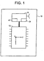
- FIG. 1 is an illustration of an exemplary embodiment of the present invention.
- a sensor package 10 has a sensor 12 with an embedded processor 14.
- the sensor 12 is a three-axis magnetic sensor 12, such as a Honeywell HMC2003 three-axis magnetometer.
- the sensor 12 measures low magnetic field strengths along an X-axis, a Y-axis, and a Z-axis wherein changes outside of a given range in the magnetic field around the sensor can be detected.
- the sensor provides an analog signal and the ground, or earth, is used as the magnetic field reference.
- the processor 14 is provided to allow for communication of magnetic field readings between a sensor 12 connected to the processor, a plurality of sensors 12 and a wayside unit, or communication device, 16 and/or a locomotive 18. Communication can occur over industry standard networks such as, but not limited to, a Controller Area Network ("CAN"). CAN is an electronics industry standard vital protocol used for communication between embedded processors. Communication also can occur between the wayside unit 16, a train 20, and a service facility, or depot, 22, as illustrated in FIG. 2 . Though not illustrated, communication can also occur between the wayside unit 16 and railway equipment operable to prevent train movement towards the railway where the change in magnetic field has been detected.
- CAN Controller Area Network
- the processor 14 will also digitize the analog signal provided from the sensor 12. Depending on the type of application the sensor/processor package 10 is being used for, as will be discussed below in more detail, the processor 14 will apply a specific software filter algorithm 24 to the signal to further reduce noise. Furthermore, based on commands received from the wayside unit 16, the processor 14 will also function to measure the outputs from the sensor 12 and save the measurements as a zero reference value to be used as a reference for any magnetic field changes detected.
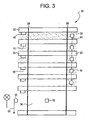
- FIG. 3 is an illustration of exemplary embodiments of how the sensor/processor packages 10 are used with a railway 30.
- the sensor/processor package 10 is placed within the ballast material 32, attached to railway ties 33 and/or placed within a railroad crossing area 34.
- the packages 10 are placed at fixed intervals which determine an amount of coverage desired.
- the wayside unit 16 interfaces with the sensors 12, via each respective sensor's processor 14 via the communication network 40, 41. Communication between the sensor/processor packages 10 and the wayside unit 16 can occur through a wireless network 40, a wired network 41, and/or a combination of both.
- the wayside unit 16 is operable to command the sensors 12 to zero reference output as well as to communicate 45 with a train 20 and/or depot 22 via radio and/or other communication protocols. The type of detection resolution would be determined by how many sensor/processor packages are installed.
- the uses of the present invention are numerous, several uses are readily identifiable.
- a network of the present invention in an automobile crossing area of a railroad track 34, or railroad crossing, it is possible to detect automobiles present in the crossing area 34 as a train 20 is approaching the crossing area 34. This is possible due to the sensor(s) 12 detecting a change in the magnetic field over the crossing area 34.
- the processor 14 applies a low pass filter 47 to the sensor output to eliminate any noise interference.
- the low pass filter cutoff frequency is high enough to allow detection of objects passing through the crossing area 34, especially if any objects remain over the crossing area 34.
- the wayside unit 16 receives a signal from the crossing sensor (not illustrated) to indicate that the train 20 is approaching and that the crossing guard is activating.
- the wayside unit 16 communicates to the crossing system if the crossing is clear of automobiles, using the sensor/processing package 10, and also relays this information to the locomotive 20.
- the wayside unit 16 is configured to constantly supply crossing status to the crossing detector. If an automobile were upon the tracks 30, a warning is sent via the wayside unit 16, to the approaching train 20.
- the sensor/processing package 10 is attached to the crossing guard arm.
- the arm 51 When the arm 51 lowers into place when a train 20 is approaching, if the magnetic field around it is different, or in other words if a vehicle is detected as being on the tracks, the arm will automatically lift allowing the vehicle to leave the crossing area without having to break the crossing arm 51.
- Another application for the present invention is for detecting shifted rail and another is for pumping ties. Tie 33 movement in three directions is detectable using the present invention and the earth's magnetic field for reference. Likewise, a shifted rail is also detectable prior to a train approaching that part of the track.
- the wayside unit 16 applies a low pass filter 47 to the sensors at a high enough cutoff frequency to detect tie movement for all train speeds.
- the wayside unit 16 reports track status to the depot 22. If a change in track conditions is detected, specifically a change in tie 33 location is detected, in addition to reporting the change to the depot 22, a warning signal is sent to any locomotives 18 that are approaching that part of the track 30.
- the signal 45 reported to any approaching trains 20 can be, but is not limited to, an alarm, voice message, etc.
- the signal 45 may also be sent to other railway equipment, such as an interlocking (not illustrated) to block train movement towards the detected shifted track.
- the present invention is used to detect this problem. Since the metal of the wheels 52 of the car 54 are likely to contact the ties 33 or drag against the side of the rails 57, a change in the magnetic field would be realized since the magnetic field around the dragging wheels 52 would change when compared to the other cars 54 that make up the train 20. Towards this end, the present invention would detect the change in magnetic field caused by the dragging wheels 52.
- the present invention is used to detect ballast 32 washout.
- a network of sensor/processor packages 10 buried in the ballast 32 at fixed intervals it is possible to determine the movement of the railroad ballast 32 based on a change in the magnetic field due to ballast 32 movement.
- the processor 14 applies a very low frequency low pass filter algorithm 47 to the sensor 12 output to eliminate false signals.
- the sensor/processor package 10 outputs are monitored by the wayside unit 16 that will command the processors 14.
- the processors 14 communicate any changes detected in the magnetic field to the wayside unit 16.
- the wayside unit 16 sends a signal warning and/or status report 45 to, via voice message, alarm, etc., approaching trains 20, a communication to a railroad service facility 22, or a communication to signal controlling equipment such as an interlocking to block train movement over that stretch of rail.
Landscapes
- Engineering & Computer Science (AREA)
- Mechanical Engineering (AREA)
- Train Traffic Observation, Control, And Security (AREA)
- Geophysics And Detection Of Objects (AREA)
Abstract
Claims (10)
- Système pour déterminer la capacité d'une voie de
chemins de fer (30) ayant :deux rails d'acier supportés par une pluralité de traverses (33) disposées perpendiculairement qui reposent sur un matériau de ballast (32) afin de supporter en toute sécurité des véhicules ferroviaires (18, 54) sur la voie (30) en captant des variations dans l'environnement proche (20) de la voie (30), le système comprenant :a) un capteur (12) pour détecter un champ magnétique à proximité de la voie de chemins de fer (30) et générer des données indicatrices du champ magnétique, dans lequel le capteur (12) est fixé dans le matériau de ballast de chemins de fer (32) afin de déterminer si le champ magnétique autour du matériau de ballast (32) varie,b) un processeur (14) pour traiter les données provenant du capteur (12) afin d'identifier des variations du champ magnétique à proximité de la voie (30) ; etc) un dispositif de communication (16) en communication avec le processeur (14) pour transmettre des indices indicateurs de variations de l'environnement proche de la voie (30) affectant la capacité de la voie (30) à supporter en toute sécurité des véhicules ferroviaires (18, 54). - Système selon la revendication 1, dans lequel le dispositif de communication (16) signale la perte de support pour la voie (30) à au moins un train (18, 54), une installation de service (22) ou un équipement de chemins de fer qui est à même d'empêcher le mouvement d'un train (18, 54) vers la voie surveillée (30).
- Système selon la revendication 1 dans lequel le capteur (12) est fixé à proximité (20) de la voie de chemin de fer (30) pour déterminer si un rail (57) a bougé.
- Système selon la revendication 1, dans lequel le capteur (12) détermine une variation du champ magnétique dans trois directions.
- Système selon la revendication 1, dans lequel le processeur (14) comprend en outre un filtre (24) pour réduire un signal de bruit détecté par le capteur (14).
- Système selon la revendication 5, dans lequel ledit filtre (24) comprend un filtre passe-bas (17).
- Procédé de détermination de la capacité d'une voie de chemins de fer (30) ayant deux rails d'acier supportés par une pluralité de traverses disposées perpendiculairement (33) qui reposent sur un matériau de ballast (32) pour supporter en toute sécurité des véhicules ferroviaires (18, 54) sur la voie (30) en captant des variations de l'environnement proche de la voie (30), le procédé comprenant les étapes consistant à :a) détecter un champ magnétique à proximité de la voie de chemins de fer (30) à l'intérieur du matériau de ballast de chemins de fer (32) afin de déterminer si le champ magnétique autour du matériau de ballast (32) varie par un capteur fixé dans le matériau de ballast de chemins de fer (32) ;b) générer des données indicatrices du champ magnétique ;c) identifier des changements de champ magnétique à proximité de la voie (30) ; etd) transmettre des indices indicateurs de variations dans l'environnement proche de la voie (30) affectant la capacité de la voie (30) à supporter en toute sécurité des véhicules ferroviaires (18, 54).
- Procédé selon la revendication 7, dans lequel l'étape de détection d'un champ magnétique proche de la voie (30) comprend en outre la détection d'objets qui ont été positionnés de manière adjacente à la voie (30) et qui peuvent interférer sur le déplacement des véhicules ferroviaires (18, 54) le long de la voie (30).
- Procédé selon la revendication 7, dans lequel l'étape de détection d'un champ magnétique à proximité de la voie (30) comprend en outre la détection d'objets qui ont été positionnés en travers de la voie (30) et qui peuvent interférer sur le déplacement des véhicules ferroviaires (18, 54) le long de la voie (30).
- Procédé selon la revendication 7, dans lequel l'étape de transmission d'indices indicateurs de variations d'environnement comprend en outre la transmission, lorsque la perte de support pour la voie (30) est détectée, à au moins un train (18, 54), une installation de services (22) ou un équipement de chemins de fer qui est à même d'empêcher un mouvement du train vers la voie surveillée (30).
Applications Claiming Priority (2)
| Application Number | Priority Date | Filing Date | Title |
|---|---|---|---|
| US11/206,959 US7575201B2 (en) | 2005-08-18 | 2005-08-18 | System and method for detecting a change or an obstruction to a railway track |
| PCT/US2006/029977 WO2007021537A1 (fr) | 2005-08-18 | 2006-08-01 | Systeme et procede de detection de modification ou d'obstacle sur une voie de chemin de fer |
Publications (2)
| Publication Number | Publication Date |
|---|---|
| EP1919754A1 EP1919754A1 (fr) | 2008-05-14 |
| EP1919754B1 true EP1919754B1 (fr) | 2011-05-04 |
Family
ID=37499515
Family Applications (1)
| Application Number | Title | Priority Date | Filing Date |
|---|---|---|---|
| EP06800628A Not-in-force EP1919754B1 (fr) | 2005-08-18 | 2006-08-01 | Systeme et procede de detection d'une modification ou d'un obstacle sur une voie de chemin de fer |
Country Status (12)
| Country | Link |
|---|---|
| US (1) | US7575201B2 (fr) |
| EP (1) | EP1919754B1 (fr) |
| JP (1) | JP5183473B2 (fr) |
| CN (1) | CN101242985B (fr) |
| AU (1) | AU2006280280A1 (fr) |
| BR (1) | BRPI0616502A2 (fr) |
| CA (1) | CA2618527A1 (fr) |
| DE (1) | DE602006021755D1 (fr) |
| MX (1) | MX2008002175A (fr) |
| RU (1) | RU2443588C2 (fr) |
| WO (1) | WO2007021537A1 (fr) |
| ZA (1) | ZA200802011B (fr) |
Families Citing this family (31)
| Publication number | Priority date | Publication date | Assignee | Title |
|---|---|---|---|---|
| US10308265B2 (en) | 2006-03-20 | 2019-06-04 | Ge Global Sourcing Llc | Vehicle control system and method |
| US9733625B2 (en) | 2006-03-20 | 2017-08-15 | General Electric Company | Trip optimization system and method for a train |
| US9950722B2 (en) | 2003-01-06 | 2018-04-24 | General Electric Company | System and method for vehicle control |
| US9956974B2 (en) | 2004-07-23 | 2018-05-01 | General Electric Company | Vehicle consist configuration control |
| US20070078574A1 (en) * | 2005-09-30 | 2007-04-05 | Davenport David M | System and method for providing access to wireless railroad data network |
| US9828010B2 (en) | 2006-03-20 | 2017-11-28 | General Electric Company | System, method and computer software code for determining a mission plan for a powered system using signal aspect information |
| JP4920538B2 (ja) * | 2007-09-26 | 2012-04-18 | 公益財団法人鉄道総合技術研究所 | 三軸加速度センサとpicマイクロコンピュータを内蔵した完全独立型の無線・光通信併用方式三次元センシングストーン |
| US20100194533A1 (en) * | 2009-01-30 | 2010-08-05 | Sullivan Henry W | Method and apparatus for encoding railroad ties and other railroad track components |
| US8914171B2 (en) | 2012-11-21 | 2014-12-16 | General Electric Company | Route examining system and method |
| US20100258682A1 (en) * | 2009-04-14 | 2010-10-14 | Jeffrey Michael Fries | System and method for interfacing wayside signal device with vehicle control system |
| CN102001346B (zh) * | 2010-10-13 | 2012-03-28 | 南京泰通科技有限公司 | 用于探测铁路异物侵限的装置 |
| JP5806068B2 (ja) * | 2011-09-30 | 2015-11-10 | 日本信号株式会社 | 列車制御システム |
| WO2014026091A2 (fr) | 2012-08-10 | 2014-02-13 | General Electric Company | Système et procédé d'examen d'itinéraire |
| FR2994984B1 (fr) * | 2012-08-30 | 2014-08-22 | Sncf | Dispositif de surveillance de la variation de distance verticale entre une voie ferroviaire et une couche de ballast |
| US9255913B2 (en) | 2013-07-31 | 2016-02-09 | General Electric Company | System and method for acoustically identifying damaged sections of a route |
| CN204719798U (zh) * | 2015-06-23 | 2015-10-21 | 黄海 | 智能道砟信息管理系统 |
| US10556606B2 (en) * | 2016-04-29 | 2020-02-11 | The Island Radar Company | Railroad car location, speed, and heading detection system and methods with self-powered wireless sensor nodes |
| US11772692B2 (en) * | 2018-11-30 | 2023-10-03 | Westinghouse Air Brake Technologies Corporation | Method and apparatus for vehicle-based switch locking in a rail network |
| WO2019086096A1 (fr) * | 2017-10-30 | 2019-05-09 | Konux Gmbh | Appareil de traitement électronique et procédé de montage d'un appareil de traitement électronique |
| WO2019086097A1 (fr) * | 2017-10-30 | 2019-05-09 | Konux Gmbh | Procédé permettant de déterminer une caractéristique d'élément d'un élément de voie ferrée |
| CN110161559A (zh) * | 2017-11-28 | 2019-08-23 | 中国铁道科学研究院 | 一种高速铁路地震预警系统 |
| CN108086070B (zh) * | 2018-02-01 | 2020-01-31 | 株洲时代电子技术有限公司 | 一种铁道线路轨枕位置测量装置 |
| CN108086071B (zh) * | 2018-02-01 | 2020-01-31 | 株洲时代电子技术有限公司 | 一种铁道线路轨枕位置定位方法 |
| JP6686073B2 (ja) * | 2018-06-06 | 2020-04-22 | 株式会社京三製作所 | 車上装置 |
| JP7039415B2 (ja) * | 2018-07-26 | 2022-03-22 | 公益財団法人鉄道総合技術研究所 | 軌道支持状態推定方法、そのプログラム及びシステム |
| CN112611313B (zh) * | 2020-12-11 | 2022-08-30 | 交控科技股份有限公司 | 轨道车辆长度测量装置、测量方法及交通设施 |
| JP7108083B1 (ja) | 2021-04-30 | 2022-07-27 | 株式会社京三製作所 | 車上装置及び判定方法 |
| GB2606397B (en) * | 2021-05-07 | 2023-07-19 | Three Smith Group Ltd | Damage detection system |
| AT525614B1 (de) * | 2021-11-10 | 2025-10-15 | Hp3 Real Gmbh | Vorrichtung zum Detektieren von Schwellen eines Gleises |
| KR102751978B1 (ko) * | 2022-07-11 | 2025-01-07 | 서울교통공사 | 고신뢰 부정출발 방지시스템 및 그 방법 |
| US20260017767A1 (en) * | 2024-07-15 | 2026-01-15 | Caterpillar Inc. | Railroad asset monitoring based on compact asset data |
Family Cites Families (24)
| Publication number | Priority date | Publication date | Assignee | Title |
|---|---|---|---|---|
| SU133648A1 (ru) * | 1959-07-30 | 1959-11-30 | А.С. Фролов | Рельсовый прогибомер |
| US4042810A (en) * | 1975-01-25 | 1977-08-16 | Halliburton Company | Method and apparatus for facilitating control of a railway train |
| US4179744A (en) * | 1978-03-02 | 1979-12-18 | Magtronics Incorporated | Method and apparatus for analyzing performance of electric-traction-motor powered vehicles and electrical operating components thereof |
| FR2562668B1 (fr) * | 1984-04-05 | 1987-11-27 | Sncf | Dispositif de reperage de defauts de rails de chemin de fer par courants de foucault, capable de discriminer les defauts de certaines discontinuites de construction des rails |
| AT399401B (de) | 1988-05-27 | 1995-05-26 | Voest Alpine Eisenbahnsysteme | Einrichtung zum erfassen des zustandes von schienenweichen oder kreuzungen |
| WO1990003622A1 (fr) * | 1988-09-28 | 1990-04-05 | Teknis Systems (Australia) Pty. Ltd. | Systeme de conservation d'energie pour vehicules sur rail |
| US5954299A (en) * | 1991-02-04 | 1999-09-21 | Eva Signal Corporation | Railroad crossing traffic warning system apparatus and method therefore |
| CA2088918C (fr) * | 1991-06-04 | 1996-07-02 | Seigo Ando | Methode de detection magnetique et appareil utilise a cet effet |
| NL9400955A (nl) | 1994-03-11 | 1995-10-02 | Mathijs Maria Johannes Engels | Inrichting en werkwijze voor het contactloos meten aan een staaf uit ferro-magnetisch materiaal. |
| JPH0813505A (ja) * | 1994-07-01 | 1996-01-16 | East Japan Railway Co | 斜面崩壊検知装置 |
| AUPN992596A0 (en) | 1996-05-17 | 1996-06-13 | Technological Resources Pty Limited | Magnetic detection of discontinuities in magnetic materials |
| US5699986A (en) * | 1996-07-15 | 1997-12-23 | Alternative Safety Technologies | Railway crossing collision avoidance system |
| US5864304A (en) * | 1996-08-08 | 1999-01-26 | At&T Corp | Wireless railroad grade crossing warning system |
| US5950967A (en) * | 1997-08-15 | 1999-09-14 | Westinghouse Air Brake Company | Enhanced distributed power |
| WO1999014093A1 (fr) * | 1997-09-12 | 1999-03-25 | New York Air Brake Corporation | Procede d'optimisation du fonctionnement d'un train et de la formation a la conduite d'un train |
| RU2153549C2 (ru) * | 1998-05-05 | 2000-07-27 | Акционерное общество открытого типа "Ракетно-космическая корпорация "Энергия" им. С.П. Королева" | Устройство определения середины шпальной накладки и электромагнитный датчик для обнаружения шпальной накладки |
| US6205946B1 (en) * | 1998-05-13 | 2001-03-27 | Daniel R. Picton | Earthen material integrity sensing device |
| US7164975B2 (en) * | 1999-06-15 | 2007-01-16 | Andian Technologies Ltd. | Geometric track and track/vehicle analyzers and methods for controlling railroad systems |
| US6553838B2 (en) * | 2000-08-25 | 2003-04-29 | Em-Tech Llc | Detection of anomalies on railroad tracks |
| US6600999B2 (en) * | 2000-10-10 | 2003-07-29 | Sperry Rail, Inc. | Hi-rail vehicle-based rail inspection system |
| AT411277B (de) * | 2001-08-09 | 2003-11-25 | Plasser Bahnbaumasch Franz | Maschine und verfahren zum erkennen der schwellenlage eines gleises |
| GB0202740D0 (en) * | 2002-02-06 | 2002-03-27 | Gentech Internat Ltd | Improvements in and relating to measuring of displacement |
| JP4044808B2 (ja) * | 2002-08-13 | 2008-02-06 | 邦博 岸田 | 移動体検出システム |
| GB2424981B (en) | 2004-11-24 | 2010-10-27 | Timothy Laurie Somner | System for detecting the presence of an intruding body |
-
2005
- 2005-08-18 US US11/206,959 patent/US7575201B2/en active Active
-
2006
- 2006-08-01 BR BRPI0616502-8A patent/BRPI0616502A2/pt not_active IP Right Cessation
- 2006-08-01 RU RU2008110175/11A patent/RU2443588C2/ru not_active IP Right Cessation
- 2006-08-01 WO PCT/US2006/029977 patent/WO2007021537A1/fr not_active Ceased
- 2006-08-01 AU AU2006280280A patent/AU2006280280A1/en not_active Abandoned
- 2006-08-01 CA CA002618527A patent/CA2618527A1/fr not_active Abandoned
- 2006-08-01 DE DE602006021755T patent/DE602006021755D1/de active Active
- 2006-08-01 EP EP06800628A patent/EP1919754B1/fr not_active Not-in-force
- 2006-08-01 JP JP2008526962A patent/JP5183473B2/ja not_active Expired - Fee Related
- 2006-08-01 CN CN2006800301002A patent/CN101242985B/zh not_active Expired - Fee Related
- 2006-08-01 MX MX2008002175A patent/MX2008002175A/es active IP Right Grant
-
2008
- 2008-03-03 ZA ZA200802011A patent/ZA200802011B/xx unknown
Also Published As
| Publication number | Publication date |
|---|---|
| RU2443588C2 (ru) | 2012-02-27 |
| CN101242985B (zh) | 2010-10-27 |
| JP5183473B2 (ja) | 2013-04-17 |
| ZA200802011B (en) | 2008-12-31 |
| DE602006021755D1 (de) | 2011-06-16 |
| US20070040068A1 (en) | 2007-02-22 |
| JP2009504501A (ja) | 2009-02-05 |
| BRPI0616502A2 (pt) | 2011-06-21 |
| MX2008002175A (es) | 2008-04-22 |
| CN101242985A (zh) | 2008-08-13 |
| AU2006280280A1 (en) | 2007-02-22 |
| WO2007021537A1 (fr) | 2007-02-22 |
| RU2008110175A (ru) | 2009-09-27 |
| EP1919754A1 (fr) | 2008-05-14 |
| US7575201B2 (en) | 2009-08-18 |
| CA2618527A1 (fr) | 2007-02-22 |
Similar Documents
| Publication | Publication Date | Title |
|---|---|---|
| EP1919754B1 (fr) | Systeme et procede de detection d'une modification ou d'un obstacle sur une voie de chemin de fer | |
| EP2585353B1 (fr) | Système et méthode pour déterminer la position d'objets sur une voie ferrée | |
| WO2014027977A1 (fr) | Procédé de détection de fractures et de fissures de rail | |
| CN105813907A (zh) | 铁路车辆信号执行和分离控制 | |
| WO2016039789A1 (fr) | Système de détection de rails cassés pour systèmes de chemin de fer | |
| EP3971052B1 (fr) | Appareil de détection de l'état de surface de roues de véhicule ferroviaire | |
| AU2011308097A1 (en) | A railroad track inspection vehicle | |
| AU2013101775A4 (en) | Vehicle Detection System | |
| KR101029516B1 (ko) | 궤도차량 위치 검지 시스템 | |
| AU2023204565A1 (en) | Monitoring system of a railroad axle and peripherals | |
| JP4913544B2 (ja) | 衝突検知方法 | |
| KR102679135B1 (ko) | 레일 변위 측정 시스템 | |
| JP7630893B2 (ja) | 運転再開判定装置及び運転再開支援システム | |
| AU2018201894A1 (en) | A safety device for a railway vehicle, a railway vehicle, a method for preserving safety of such a railway vehicle, and associated computer program |
Legal Events
| Date | Code | Title | Description |
|---|---|---|---|
| PUAI | Public reference made under article 153(3) epc to a published international application that has entered the european phase |
Free format text: ORIGINAL CODE: 0009012 |
|
| 17P | Request for examination filed |
Effective date: 20080318 |
|
| AK | Designated contracting states |
Kind code of ref document: A1 Designated state(s): DE FR GB |
|
| DAX | Request for extension of the european patent (deleted) | ||
| RBV | Designated contracting states (corrected) |
Designated state(s): DE FR GB |
|
| 17Q | First examination report despatched |
Effective date: 20090729 |
|
| RAP1 | Party data changed (applicant data changed or rights of an application transferred) |
Owner name: PROGRESS RAIL SERVICES CORPORATION |
|
| GRAP | Despatch of communication of intention to grant a patent |
Free format text: ORIGINAL CODE: EPIDOSNIGR1 |
|
| GRAS | Grant fee paid |
Free format text: ORIGINAL CODE: EPIDOSNIGR3 |
|
| GRAA | (expected) grant |
Free format text: ORIGINAL CODE: 0009210 |
|
| AK | Designated contracting states |
Kind code of ref document: B1 Designated state(s): DE FR GB |
|
| REG | Reference to a national code |
Ref country code: GB Ref legal event code: FG4D |
|
| REF | Corresponds to: |
Ref document number: 602006021755 Country of ref document: DE Date of ref document: 20110616 Kind code of ref document: P |
|
| REG | Reference to a national code |
Ref country code: DE Ref legal event code: R096 Ref document number: 602006021755 Country of ref document: DE Effective date: 20110616 |
|
| PLBE | No opposition filed within time limit |
Free format text: ORIGINAL CODE: 0009261 |
|
| STAA | Information on the status of an ep patent application or granted ep patent |
Free format text: STATUS: NO OPPOSITION FILED WITHIN TIME LIMIT |
|
| 26N | No opposition filed |
Effective date: 20120207 |
|
| REG | Reference to a national code |
Ref country code: FR Ref legal event code: ST Effective date: 20120430 |
|
| REG | Reference to a national code |
Ref country code: DE Ref legal event code: R097 Ref document number: 602006021755 Country of ref document: DE Effective date: 20120207 |
|
| PG25 | Lapsed in a contracting state [announced via postgrant information from national office to epo] |
Ref country code: FR Free format text: LAPSE BECAUSE OF NON-PAYMENT OF DUE FEES Effective date: 20110831 |
|
| PGFP | Annual fee paid to national office [announced via postgrant information from national office to epo] |
Ref country code: DE Payment date: 20120831 Year of fee payment: 7 |
|
| PG25 | Lapsed in a contracting state [announced via postgrant information from national office to epo] |
Ref country code: DE Free format text: LAPSE BECAUSE OF NON-PAYMENT OF DUE FEES Effective date: 20140301 |
|
| REG | Reference to a national code |
Ref country code: DE Ref legal event code: R119 Ref document number: 602006021755 Country of ref document: DE Effective date: 20140301 |
|
| PGFP | Annual fee paid to national office [announced via postgrant information from national office to epo] |
Ref country code: GB Payment date: 20140725 Year of fee payment: 9 |
|
| GBPC | Gb: european patent ceased through non-payment of renewal fee |
Effective date: 20150801 |
|
| PG25 | Lapsed in a contracting state [announced via postgrant information from national office to epo] |
Ref country code: GB Free format text: LAPSE BECAUSE OF NON-PAYMENT OF DUE FEES Effective date: 20150801 |