EP1919773B1 - Verfahren und gerät zur verbesserung der ermüdungsbeständigkeit des hauptrotorsattels - Google Patents
Verfahren und gerät zur verbesserung der ermüdungsbeständigkeit des hauptrotorsattels Download PDFInfo
- Publication number
- EP1919773B1 EP1919773B1 EP06849797A EP06849797A EP1919773B1 EP 1919773 B1 EP1919773 B1 EP 1919773B1 EP 06849797 A EP06849797 A EP 06849797A EP 06849797 A EP06849797 A EP 06849797A EP 1919773 B1 EP1919773 B1 EP 1919773B1
- Authority
- EP
- European Patent Office
- Prior art keywords
- rotor
- flapping
- craft
- error
- control
- Prior art date
- Legal status (The legal status is an assumption and is not a legal conclusion. Google has not performed a legal analysis and makes no representation as to the accuracy of the status listed.)
- Not-in-force
Links
Images
Classifications
-
- B—PERFORMING OPERATIONS; TRANSPORTING
- B64—AIRCRAFT; AVIATION; COSMONAUTICS
- B64C—AEROPLANES; HELICOPTERS
- B64C27/00—Rotorcraft; Rotors peculiar thereto
- B64C27/54—Mechanisms for controlling blade adjustment or movement relative to rotor head, e.g. lag-lead movement
- B64C27/56—Mechanisms for controlling blade adjustment or movement relative to rotor head, e.g. lag-lead movement characterised by the control initiating means, e.g. manually actuated
- B64C27/57—Mechanisms for controlling blade adjustment or movement relative to rotor head, e.g. lag-lead movement characterised by the control initiating means, e.g. manually actuated automatic or condition responsive, e.g. responsive to rotor speed, torque or thrust
-
- B—PERFORMING OPERATIONS; TRANSPORTING
- B64—AIRCRAFT; AVIATION; COSMONAUTICS
- B64C—AEROPLANES; HELICOPTERS
- B64C27/00—Rotorcraft; Rotors peculiar thereto
- B64C27/001—Vibration damping devices
-
- G—PHYSICS
- G05—CONTROLLING; REGULATING
- G05D—SYSTEMS FOR CONTROLLING OR REGULATING NON-ELECTRIC VARIABLES
- G05D1/00—Control of position, course, altitude or attitude of land, water, air or space vehicles, e.g. using automatic pilots
- G05D1/40—Control within particular dimensions
- G05D1/49—Control of attitude, i.e. control of roll, pitch or yaw
-
- G—PHYSICS
- G05—CONTROLLING; REGULATING
- G05D—SYSTEMS FOR CONTROLLING OR REGULATING NON-ELECTRIC VARIABLES
- G05D2109/00—Types of controlled vehicles
- G05D2109/20—Aircraft, e.g. drones
- G05D2109/25—Rotorcrafts
Definitions
- GB-A-2,050,980 discloses a helicopter elevator driven by an electrical actuator to position the elevator to an optimum angle of incidence for given flight conditions.
- the actuator is included within a servo loop which corresponds to a command signal derived from an electronics module.
- Transducers which measure longitudinal cyclic position, collective pitch position and air speed generate signals which are summed in a summation unit.
- the output of the summation unit is passed through a multiplication unit which has bits gain set inversely proportional to air speed.
- US-A-4,580,223 discloses an aircraft automatic flight control system including a pair of fast, limited authority inner loop actuators responsive to signals indicative of aircraft attitude or other flight parameters such as airspeed.
- the inner loop is re-centred by an outer loop actuator responsive to attitude or other aircraft parameter-indicating signals.
- US-A-4,032,083 discloses a method for automatically varying the gain of a stability augmentation system for an aircraft such as a helicopter.
- the gain is automatically varied in accordance with the gross weight and deviations of the centre of gravity of the aircraft.
- Gross weight and centre of gravity are identified from in-flight measurements of collective and cyclic pitch stick position and airspeed. The gain of the stability augmentation system will not be changed during periods when the aircraft is being manoeuvred.
- the present invention stems from a recognition that most damage to the yoke occurs during manoeuvres, as opposed to during trimmed flight at a normal load factor of 1.0g where typically no yoke fatigue damage is incurred.
- most damage occurs during aircraft pull-up manoeuvres where the load factor is increasing above 1.0g since such types of pilot manoeuvres typically involve the most significant and most frequent bending load applications on the rotor.
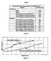
- Table 1 presents the usage spectrum for an example rotorcraft. As seen in the table, the pullout manoeuvres per 100 flight hours greatly outnumber the pushover manoeuvres.
- the number of pullout manoeuvres resulting in a normal load factor of approximately 2.0g, or an increase of 1.0g would be 150 per 100 flight hours.
- the number of pushover manoeuvres resulting in 0.0g, or a decrease of 1.0g is less than one per 100 flight hours.
- the longitudinal cyclic control position, pitch attitude, and rotor flapping state for trimmed, 1-g flight conditions vary depending on the weight, center of gravity, altitude, and airspeed of the rotorcraft.
- the tendency may exist for an aircraft to trim with an undesirable nose-high attitude when the center of gravity of the aircraft is near the aft portion of its allowable range.
- the method according to claim 1 of the present invention advantageously allows the helicopter to be automatically trimmed toward a desired trim position.
- the rotor flapping of a helicopter can be automatically trimmed toward the forward flapping endurance limit in order to decrease damaging yoke loads during pull-up maneuvers and increase overall yoke life.
- the automatic trimming can be accomplished by adjusting the elevator incidence angle based upon a feedback of measured aircraft parameters.
- the measured aircraft parameters are indicators of the flapping state of the rotor and are compared to target values that will provide an optimum flapping state of the rotor.
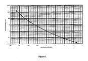
- Figure 1 is a graph showing the effect of rotor load on rotor fatigue life.
- Figure 2 is a table that presents a usage spectrum for an example rotorcraft.
- Figure 3 is a graph that plots rotor yoke load against g-force for various maneuvers, for nominal rotor flapping and with the rotor biased towards forward flapping.
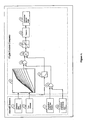
- Figure 4 is a schematic representation of the method and system employed in accordance with one embodiment of the present invention.
- rotor flapping is comprised of two components.
- the first component is a function of the thrust coefficient, C T , and the advance ratio, ⁇ , of the rotor.
- C T is a function of the rotor collective control position
- ⁇ is a function of the airspeed of the helicopter.
- the second flapping component is a function of the cyclic control input to the rotor, primarily longitudinal cyclic. Therefore, total rotor flapping can be accurately approximated using the longitudinal cyclic input, the collective position, and the measured (true) airspeed.
- these three parameters are readily available parameters that are measured in most rotorcraft.
- transducers or encoders are used to measure the longitudinal cyclic and collective control positions.
- an airspeed transducer can be used to measure the airspeed of the helicopter.
- the flapping state can be determined and controlled by these parameters.
- the elevator incidence is controlled according to the control law diagram in Figure 4 .
- the measured collective stick position (1) and true airspeed (2) are applied to a 2-D table look-up function (5).
- the measured collective stick position (1) which is controlled/positioned by the pilot, is measured with a potentiometer (or other similar device) to provide an electric signal to the flight control computer that is proportional to the displacement of the collective stick.
- the measured collective stick position is a measurement of aircraft thrust (the thrust coefficient).
- the true airspeed (2) which (as known in the art) is the relative speed between the aircraft and the air, is measured as a signal from the airspeed transducers (such as a pitot-static system, LAADS computer, or other similar device) that process the calculation of true airspeed for use in the flight control computer.
- the airspeed transducers such as a pitot-static system, LAADS computer, or other similar device
- Total rotor flapping is essentially made up of two components.
- One component of rotor flapping is due to the collective input to the rotor and the airspeed of the aircraft and is determined by the flight condition of the rotorcraft. This component can be determined by analysis and verified through flight test data.
- the second component of flapping is due to the cyclic control inputs to the rotor. The sum of the two components defines the total flapping state of the rotor.
- One aspect of this invention is to control total rotor flapping, which is a known value.
- the flapping component due to collective position and airspeed is determined by the flight condition of the rotorcraft, the flapping component due to the longitudinal cyclic input to the rotor can essentially be determined so that the sum of the two components equals the target flapping value.
- the resulting commanded longitudinally cyclic position can be determined for all combinations of collective position and airspeed.
- the commanded longitudinal cyclic position can be determined so that the target flapping value is satisfied for all flight conditions.
- actual longitudinal cyclic input to the rotor can be forced to match the commanded longitudinal stick position (X) to control rotor flapping.
- the collective stick position (1) and true airspeed (2) can be used to determine the commanded longitudinal stick position, and thus be used in combination with the actual longitudinal stick position (Y) to indirectly measure rotor flapping.
- a 2-D table look-up function (5) is utilized to derive a commanded longitudinal cyclic stick position (X), based upon input signals representative of the collective stick position (1) and true airspeed (2).
- the commanded longitudinal cyclic stick position (X) can be considered a desired or ideal longitudinal stick position, for simultaneously achieving both target flapping and high static stability.
- the 2-D look up-table (5) is comprised of data that is established by flight test simulation and analysis, flight test data mapping, and verification.
- the measured actual longitudinal cyclic stick position (3) which is controlled/positioned by the pilot, and the longitudinal stability and control augmentation system (SCAS), which is input to the rotor (4) by the flight control system, are applied to a summation unit (8) to determine the total or actual longitudinal cyclic input to the aircraft rotor.
- the measured longitudinal cyclic stick position (3) is measured with a potentiometer (or other similar device) to change an electric signal to the flight control computer that is proportional to the displacement of the longitudinal cyclic stick.
- the longitudinal cyclic SCAS input is measured with a potentiometer (or other similar device) to change an electric signal to the flight control computer that is proportional to the displacement of the longitudinal cyclic SCAS actuators.
- the output signal from the summation unit (8) and the output from the 2-D table look-up function (5) are then applied to a subtraction unit (6).
- the signal output of the subtraction unit (6) is the error (Z) between the commanded longitudinal cyclic position and the actual longitudinal cyclic input.
- This signal error (Z) in the longitudinal stick position is applied to a signal multiplier (7), which provides a gain on the error.
- the aerodynamic effectiveness of the elevator is directly proportional to airspeed. As airspeed increases, the elevator becomes more effective and requires less incidence change to eliminate a given error in longitudinal cyclic position. Therefore, the measured true airspeed (2) is applied to a 1-D table look-up function (9).
- the output from the 1-D table look-up function (9) represents a gain or scaling factor to be applied to the longitudinal cyclic error by means of the signal multiplier (7).
- the magnitude of the gain decreases with increasing airspeed, which results in a reduced elevator rate at higher speeds for a given longitudinal cyclic position error.
- the output of the signal multiplier (7) may be considered the desired rate of elevator movement. This output from signal multiplier (7) is provided to a signal limiter (10) to control or limit the rate of movement of the elevator and thus prevent overdisturbance of the aircraft.
- the output of the signal limiter (10) is supplied to an integrator (11).
- the integrator (11) continues to integrate the command and move the elevator until the error (Z) in the longitudinal cyclic stick position is sufficiently reduced (e.g., reaches zero or substantially zero). In other words, the elevator incidence is adjusted until the longitudinal cyclic error is eliminated and the desired rotor flapping state is achieved.
- the output of the integrator (11) is a commanded elevator incidence angle (12).
- This methodology provides the ability to bias the rotor flapping toward the forward endurance limit to allow for aft flapping during pull-up maneuvers with little or no damage to the yoke.
- a canard can be used to adjust the pitching moment of the aircraft to achieve the desired rotor flapping.
- the present invention achieves the benefits noted above, while at the same time provides the ability to explicitly define the longitudinal static stability of the aircraft.
- the control algorithm implemented in this invention determines the desired longitudinal cyclic position as a function of measured collective control position and airspeed. As a result, the algorithm defines the longitudinal cyclic gradient versus airspeed for a given collective setting, which is the definition of static longitudinal stability. This benefit can be realized while maintaining positive attitude stability of the aircraft.
Landscapes
- Engineering & Computer Science (AREA)
- Aviation & Aerospace Engineering (AREA)
- Mechanical Engineering (AREA)
- General Physics & Mathematics (AREA)
- Remote Sensing (AREA)
- Physics & Mathematics (AREA)
- Radar, Positioning & Navigation (AREA)
- Automation & Control Theory (AREA)
- Control Of Position, Course, Altitude, Or Attitude Of Moving Bodies (AREA)
- Toys (AREA)
- Motorcycle And Bicycle Frame (AREA)
- Elevator Control (AREA)
- Turbine Rotor Nozzle Sealing (AREA)
Claims (13)
- Verfahren zum Steuern eines Drehflügler-Fluges während dem Trimmen, ohne direktes Messen des Rotorschlags, wobei das Verfahren umfasst:a) Vorgabe eines bestimmten Zielrotorschlagtrimmzustands,b) Messen einer kollektiven Steuerhebelstellung,c) Messen der Fluggeschwindigkeit des Drehflüglers,d) Verwenden von a), b) und c), um eine zyklische Solllängs-Steuerknüppel-Position während des Trimmfluges zu bestimmen, unde) Bewegen einer Steuerfläche des Drehflüglers, um ein Längsstabilitätsmoment des Drehflüglers zu verändern, bis eine Messabweichung zwischen der zyklischen Istlängs-Stellung und der zyklischen Solllängs-Stellung im Wesentlichen Null ist.
- Verfahren nach Anspruch 1, bei dem der bestimmte Zielrotorschlagtrimmzustand ein Vorwärts-Trimmzustand ist, der dazu führt, dass der Rotorschlag in Richtung einer nach vorn geneigten Schlagstellung eingestellt ist, wodurch ein Puffer für den Rotorschlag vorgesehen ist, der während des Pull-up-Vorgangs nach hinten wandert, bevor eine Belastungsobergrenze für den Schlag aufgrund des durch den Vorgang erzeugten Heckschlags annähernd erreicht oder überschritten ist.
- Verfahren nach Anspruch 1, bei dem die Drehflügler-Flugsteuerfläche durch die Anordnung des Höhenleitwerks des Drehflüglers vorgesehen ist.
- Verfahren nach Anspruch 1, weiterhin umfassend die Verwendung eines Stabilitäts- und Steuerverstärkungssystems (SCAS) zum Erzeugen eines Steuerknüppelsignals (longitudinal cyclic signal), das ebenfalls zum Steuern der Steuerfläche des Drehflüglers Verwendung findet.
- Verfahren nach Anspruch 4, bei dem das durch das Stabilitäts- und Steuerverstärkungssignal (SCAS) erzeugte Signal in Verbindung mit einer gemessenen Steuerknüppelstellung des zyklischen Steuerknüppels zum Ableiten der zyklischen Istlängs-Stellung verwendet wird, wobei die zyklische Istlängs-Stellung zum Steuern der Steuerflächen des Drehflüglers verwendet wird.
- Verfahren nach Anspruch 1, weiterhin umfassend das Skalieren der Messabweichung mit der Fluggeschwindigkeit durch Multiplizieren der Messabweichung mit einem Verstärkungsfaktor, der eine Funktion der Fluggeschwindigkeit ist.
- Verfahren nach Anspruch 1, weiterhin umfassend die Beschränkung (10) des Umfangs der Messabweichung.
- Verfahren nach Anspruch 7, weiterhin umfassend die Integration (11) der skalierten und beschränkten Messabweichung.
- Verfahren nach Anspruch 8, weiterhin umfassend das fortgesetzte Integrieren der beschränkten Messabweichung, bis der Umfang der Messabweichung auf ein vorbestimmtes Niveau reduziert ist.
- Verfahren nach Anspruch 9, bei dem sich der Umfang der Messabweichung auf Null beläuft.
- Verfahren nach Anspruch 9, bei dem das Ergebnis der integrierten Messabweichung ein befohlener Anstellwinkel (12) für das Höhenleitwerk ist, der zum Steuern des Rotorschlags des Drehflüglers Anwendung findet.
- Verfahren nach Anspruch 1, weiterhin umfassend das Bestimmen der statischen Längsstabilität des Drehflüglers durch Bestimmen eines zyklischen Längsgradienten gegenüber der Fluggeschwindigkeit für eine gegebene Hebeleinstellung.
- Verfahren nach Anspruch 12, bei dem die statische Längsstabilität einen positiven Wert aufweist.
Applications Claiming Priority (2)
| Application Number | Priority Date | Filing Date | Title |
|---|---|---|---|
| US11/215,317 US7762501B2 (en) | 2005-08-31 | 2005-08-31 | Method and apparatus for improving main rotor yoke fatigue life |
| PCT/US2006/025741 WO2007111625A2 (en) | 2005-08-31 | 2006-06-30 | Method and apparatus for improving main rotor yoke fatigue life |
Publications (2)
| Publication Number | Publication Date |
|---|---|
| EP1919773A2 EP1919773A2 (de) | 2008-05-14 |
| EP1919773B1 true EP1919773B1 (de) | 2012-11-28 |
Family
ID=37805404
Family Applications (1)
| Application Number | Title | Priority Date | Filing Date |
|---|---|---|---|
| EP06849797A Not-in-force EP1919773B1 (de) | 2005-08-31 | 2006-06-30 | Verfahren und gerät zur verbesserung der ermüdungsbeständigkeit des hauptrotorsattels |
Country Status (11)
| Country | Link |
|---|---|
| US (1) | US7762501B2 (de) |
| EP (1) | EP1919773B1 (de) |
| JP (1) | JP2009505900A (de) |
| KR (1) | KR20080039944A (de) |
| CN (1) | CN101287647A (de) |
| AU (1) | AU2006340847A1 (de) |
| BR (1) | BRPI0615604A2 (de) |
| CA (1) | CA2619595C (de) |
| MX (1) | MX2008002739A (de) |
| RU (1) | RU2008112151A (de) |
| WO (1) | WO2007111625A2 (de) |
Families Citing this family (4)
| Publication number | Priority date | Publication date | Assignee | Title |
|---|---|---|---|---|
| US10843796B2 (en) * | 2012-02-10 | 2020-11-24 | Merlin Technology, Inc. | Rotorcraft advanced autopilot control arrangement and methods |
| CN107942730A (zh) * | 2017-12-01 | 2018-04-20 | 中国直升机设计研究所 | 一种飞行品质半物理仿真测试方法 |
| CN109733592B (zh) * | 2018-11-23 | 2022-05-06 | 中国航空工业集团公司沈阳飞机设计研究所 | 飞机自动配平控制方法及系统 |
| CN110723277B (zh) * | 2019-11-28 | 2021-05-07 | 湖南捷飞科技有限公司 | 一种基于蚊子载人直升机的无人化数字电传操纵机构 |
Family Cites Families (9)
| Publication number | Priority date | Publication date | Assignee | Title |
|---|---|---|---|---|
| US4032083A (en) * | 1976-04-12 | 1977-06-28 | United Technologies Corporation | Automatic gain control for stability augmentation systems |
| US4168045A (en) * | 1978-02-28 | 1979-09-18 | United Technologies Corporation | Speed and collective pitch bias of helicopter longitudinal cyclic pitch |
| US4267987A (en) * | 1979-03-29 | 1981-05-19 | Mcdonnell William R | Helicopter airborne load systems and composite aircraft configurations |
| US4304375A (en) | 1979-05-17 | 1981-12-08 | Textron Inc. | Electrically controlled elevator |
| US4580223A (en) * | 1983-11-07 | 1986-04-01 | United Technologies Corporation | Incorporation of pitch bias actuator function into an existing AFCS |
| DE3431597A1 (de) * | 1984-08-28 | 1986-03-13 | Messerschmitt-Bölkow-Blohm GmbH, 8012 Ottobrunn | Vorrichtung zur verbesserung der laengssteuerstabilitaet von luftfahrzeugen |
| US5001646A (en) * | 1988-12-19 | 1991-03-19 | Mcdonnell Douglas Corporation | Automated helicopter flight control system |
| US5751609A (en) * | 1996-10-24 | 1998-05-12 | The United States Of America As Represented By The Secretary Of The Navy | Neural network based method for estimating helicopter low airspeed |
| US6592071B2 (en) * | 2001-09-25 | 2003-07-15 | Sikorsky Aircraft Corporation | Flight control system for a hybrid aircraft in the lift axis |
-
2005
- 2005-08-31 US US11/215,317 patent/US7762501B2/en active Active
-
2006
- 2006-06-30 AU AU2006340847A patent/AU2006340847A1/en not_active Abandoned
- 2006-06-30 MX MX2008002739A patent/MX2008002739A/es not_active Application Discontinuation
- 2006-06-30 EP EP06849797A patent/EP1919773B1/de not_active Not-in-force
- 2006-06-30 BR BRPI0615604-5A patent/BRPI0615604A2/pt not_active Application Discontinuation
- 2006-06-30 JP JP2008529028A patent/JP2009505900A/ja active Pending
- 2006-06-30 CN CNA2006800319646A patent/CN101287647A/zh active Pending
- 2006-06-30 WO PCT/US2006/025741 patent/WO2007111625A2/en not_active Ceased
- 2006-06-30 KR KR1020087004702A patent/KR20080039944A/ko not_active Withdrawn
- 2006-06-30 RU RU2008112151/11A patent/RU2008112151A/ru unknown
- 2006-06-30 CA CA2619595A patent/CA2619595C/en active Active
Also Published As
| Publication number | Publication date |
|---|---|
| WO2007111625A2 (en) | 2007-10-04 |
| RU2008112151A (ru) | 2009-10-10 |
| CA2619595C (en) | 2015-02-03 |
| BRPI0615604A2 (pt) | 2011-05-24 |
| WO2007111625A3 (en) | 2007-11-15 |
| KR20080039944A (ko) | 2008-05-07 |
| JP2009505900A (ja) | 2009-02-12 |
| MX2008002739A (es) | 2008-03-26 |
| US20070050099A1 (en) | 2007-03-01 |
| CN101287647A (zh) | 2008-10-15 |
| CA2619595A1 (en) | 2007-10-04 |
| AU2006340847A1 (en) | 2007-10-04 |
| EP1919773A2 (de) | 2008-05-14 |
| US7762501B2 (en) | 2010-07-27 |
Similar Documents
| Publication | Publication Date | Title |
|---|---|---|
| CN110395397B (zh) | 复合飞机的俯仰和推力控制 | |
| US4168045A (en) | Speed and collective pitch bias of helicopter longitudinal cyclic pitch | |
| CA2270501C (en) | Method of reducing wind gust loads acting on an aircraft | |
| CN107065899B (zh) | 用于保护飞行器最大升力能力的方法和装置 | |
| EP0193442A1 (de) | Wölbungselbstregelung | |
| US8423206B2 (en) | Variable maximum commandable roll rate for directional control during engine-out rolling maneuver | |
| US11299289B1 (en) | Angle-of-attack determination for aircraft stall protection | |
| CN110799420A (zh) | 用于控制起飞推力的系统和方法 | |
| US9703294B2 (en) | Advanced control relationship for a deflectable stabilizer | |
| EP3197774B1 (de) | Differenzrollmomentsteuerung im dauerzustand mit seitenregelung mit automatisiertem differenzial | |
| US11396363B2 (en) | Open and closed control of actuators, which drive aerodynamic control surfaces of an aircraft | |
| EP2826707B1 (de) | Rückkoppelungssystem für eine flugsteuerung eines luftfahrzeugs | |
| EP1919773B1 (de) | Verfahren und gerät zur verbesserung der ermüdungsbeständigkeit des hauptrotorsattels | |
| US11604481B2 (en) | Method for piloting a hybrid helicopter having an airframe maintained at constant incidence by regulating a position of at least one mobile tail unit surface | |
| US11292589B2 (en) | Method of automatically adjusting lift provided for a hybrid rotorcraft, and an associated hybrid rotorcraft | |
| CN113492971B (zh) | 飞行装置及其控制方法和控制装置 | |
| EP4303687B1 (de) | Mischluftgeschwindigkeitstechnik für hubschraubersteuerung bei niedrigen luftgeschwindigkeiten | |
| RU2774495C1 (ru) | Способ пилотирования гибридного вертолета, имеющего планер, удерживаемый с постоянным углом атаки посредством регулирования положения по меньшей мере одной подвижной плоскости оперения | |
| Gilson | Semi-automatic aircraft control system |
Legal Events
| Date | Code | Title | Description |
|---|---|---|---|
| PUAI | Public reference made under article 153(3) epc to a published international application that has entered the european phase |
Free format text: ORIGINAL CODE: 0009012 |
|
| 17P | Request for examination filed |
Effective date: 20080215 |
|
| AK | Designated contracting states |
Kind code of ref document: A2 Designated state(s): AT BE BG CH CY CZ DE DK EE ES FI FR GB GR HU IE IS IT LI LT LU LV MC NL PL PT RO SE SI SK TR |
|
| AX | Request for extension of the european patent |
Extension state: AL BA HR MK RS |
|
| 17Q | First examination report despatched |
Effective date: 20081204 |
|
| GRAP | Despatch of communication of intention to grant a patent |
Free format text: ORIGINAL CODE: EPIDOSNIGR1 |
|
| DAX | Request for extension of the european patent (deleted) | ||
| GRAS | Grant fee paid |
Free format text: ORIGINAL CODE: EPIDOSNIGR3 |
|
| GRAA | (expected) grant |
Free format text: ORIGINAL CODE: 0009210 |
|
| AK | Designated contracting states |
Kind code of ref document: B1 Designated state(s): AT BE BG CH CY CZ DE DK EE ES FI FR GB GR HU IE IS IT LI LT LU LV MC NL PL PT RO SE SI SK TR |
|
| REG | Reference to a national code |
Ref country code: GB Ref legal event code: FG4D |
|
| REG | Reference to a national code |
Ref country code: CH Ref legal event code: EP |
|
| REG | Reference to a national code |
Ref country code: AT Ref legal event code: REF Ref document number: 586017 Country of ref document: AT Kind code of ref document: T Effective date: 20121215 |
|
| REG | Reference to a national code |
Ref country code: IE Ref legal event code: FG4D |
|
| REG | Reference to a national code |
Ref country code: DE Ref legal event code: R096 Ref document number: 602006033404 Country of ref document: DE Effective date: 20130124 |
|
| REG | Reference to a national code |
Ref country code: AT Ref legal event code: MK05 Ref document number: 586017 Country of ref document: AT Kind code of ref document: T Effective date: 20121128 |
|
| REG | Reference to a national code |
Ref country code: NL Ref legal event code: VDEP Effective date: 20121128 |
|
| REG | Reference to a national code |
Ref country code: LT Ref legal event code: MG4D |
|
| PG25 | Lapsed in a contracting state [announced via postgrant information from national office to epo] |
Ref country code: ES Free format text: LAPSE BECAUSE OF FAILURE TO SUBMIT A TRANSLATION OF THE DESCRIPTION OR TO PAY THE FEE WITHIN THE PRESCRIBED TIME-LIMIT Effective date: 20130311 Ref country code: SE Free format text: LAPSE BECAUSE OF FAILURE TO SUBMIT A TRANSLATION OF THE DESCRIPTION OR TO PAY THE FEE WITHIN THE PRESCRIBED TIME-LIMIT Effective date: 20121128 Ref country code: FI Free format text: LAPSE BECAUSE OF FAILURE TO SUBMIT A TRANSLATION OF THE DESCRIPTION OR TO PAY THE FEE WITHIN THE PRESCRIBED TIME-LIMIT Effective date: 20121128 Ref country code: LT Free format text: LAPSE BECAUSE OF FAILURE TO SUBMIT A TRANSLATION OF THE DESCRIPTION OR TO PAY THE FEE WITHIN THE PRESCRIBED TIME-LIMIT Effective date: 20121128 |
|
| PG25 | Lapsed in a contracting state [announced via postgrant information from national office to epo] |
Ref country code: LV Free format text: LAPSE BECAUSE OF FAILURE TO SUBMIT A TRANSLATION OF THE DESCRIPTION OR TO PAY THE FEE WITHIN THE PRESCRIBED TIME-LIMIT Effective date: 20121128 Ref country code: GR Free format text: LAPSE BECAUSE OF FAILURE TO SUBMIT A TRANSLATION OF THE DESCRIPTION OR TO PAY THE FEE WITHIN THE PRESCRIBED TIME-LIMIT Effective date: 20130301 Ref country code: PT Free format text: LAPSE BECAUSE OF FAILURE TO SUBMIT A TRANSLATION OF THE DESCRIPTION OR TO PAY THE FEE WITHIN THE PRESCRIBED TIME-LIMIT Effective date: 20130328 Ref country code: BE Free format text: LAPSE BECAUSE OF FAILURE TO SUBMIT A TRANSLATION OF THE DESCRIPTION OR TO PAY THE FEE WITHIN THE PRESCRIBED TIME-LIMIT Effective date: 20121128 Ref country code: PL Free format text: LAPSE BECAUSE OF FAILURE TO SUBMIT A TRANSLATION OF THE DESCRIPTION OR TO PAY THE FEE WITHIN THE PRESCRIBED TIME-LIMIT Effective date: 20121128 Ref country code: SI Free format text: LAPSE BECAUSE OF FAILURE TO SUBMIT A TRANSLATION OF THE DESCRIPTION OR TO PAY THE FEE WITHIN THE PRESCRIBED TIME-LIMIT Effective date: 20121128 |
|
| PG25 | Lapsed in a contracting state [announced via postgrant information from national office to epo] |
Ref country code: AT Free format text: LAPSE BECAUSE OF FAILURE TO SUBMIT A TRANSLATION OF THE DESCRIPTION OR TO PAY THE FEE WITHIN THE PRESCRIBED TIME-LIMIT Effective date: 20121128 |
|
| PG25 | Lapsed in a contracting state [announced via postgrant information from national office to epo] |
Ref country code: DK Free format text: LAPSE BECAUSE OF FAILURE TO SUBMIT A TRANSLATION OF THE DESCRIPTION OR TO PAY THE FEE WITHIN THE PRESCRIBED TIME-LIMIT Effective date: 20121128 Ref country code: EE Free format text: LAPSE BECAUSE OF FAILURE TO SUBMIT A TRANSLATION OF THE DESCRIPTION OR TO PAY THE FEE WITHIN THE PRESCRIBED TIME-LIMIT Effective date: 20121128 Ref country code: SK Free format text: LAPSE BECAUSE OF FAILURE TO SUBMIT A TRANSLATION OF THE DESCRIPTION OR TO PAY THE FEE WITHIN THE PRESCRIBED TIME-LIMIT Effective date: 20121128 Ref country code: CY Free format text: LAPSE BECAUSE OF FAILURE TO SUBMIT A TRANSLATION OF THE DESCRIPTION OR TO PAY THE FEE WITHIN THE PRESCRIBED TIME-LIMIT Effective date: 20121128 Ref country code: BG Free format text: LAPSE BECAUSE OF FAILURE TO SUBMIT A TRANSLATION OF THE DESCRIPTION OR TO PAY THE FEE WITHIN THE PRESCRIBED TIME-LIMIT Effective date: 20130228 Ref country code: CZ Free format text: LAPSE BECAUSE OF FAILURE TO SUBMIT A TRANSLATION OF THE DESCRIPTION OR TO PAY THE FEE WITHIN THE PRESCRIBED TIME-LIMIT Effective date: 20121128 |
|
| PG25 | Lapsed in a contracting state [announced via postgrant information from national office to epo] |
Ref country code: RO Free format text: LAPSE BECAUSE OF FAILURE TO SUBMIT A TRANSLATION OF THE DESCRIPTION OR TO PAY THE FEE WITHIN THE PRESCRIBED TIME-LIMIT Effective date: 20121128 Ref country code: NL Free format text: LAPSE BECAUSE OF FAILURE TO SUBMIT A TRANSLATION OF THE DESCRIPTION OR TO PAY THE FEE WITHIN THE PRESCRIBED TIME-LIMIT Effective date: 20121128 |
|
| PLBE | No opposition filed within time limit |
Free format text: ORIGINAL CODE: 0009261 |
|
| STAA | Information on the status of an ep patent application or granted ep patent |
Free format text: STATUS: NO OPPOSITION FILED WITHIN TIME LIMIT |
|
| 26N | No opposition filed |
Effective date: 20130829 |
|
| REG | Reference to a national code |
Ref country code: DE Ref legal event code: R097 Ref document number: 602006033404 Country of ref document: DE Effective date: 20130829 |
|
| PG25 | Lapsed in a contracting state [announced via postgrant information from national office to epo] |
Ref country code: MC Free format text: LAPSE BECAUSE OF FAILURE TO SUBMIT A TRANSLATION OF THE DESCRIPTION OR TO PAY THE FEE WITHIN THE PRESCRIBED TIME-LIMIT Effective date: 20121128 |
|
| REG | Reference to a national code |
Ref country code: CH Ref legal event code: PL |
|
| REG | Reference to a national code |
Ref country code: IE Ref legal event code: MM4A |
|
| PG25 | Lapsed in a contracting state [announced via postgrant information from national office to epo] |
Ref country code: LI Free format text: LAPSE BECAUSE OF NON-PAYMENT OF DUE FEES Effective date: 20130630 Ref country code: IE Free format text: LAPSE BECAUSE OF NON-PAYMENT OF DUE FEES Effective date: 20130630 Ref country code: CH Free format text: LAPSE BECAUSE OF NON-PAYMENT OF DUE FEES Effective date: 20130630 |
|
| PG25 | Lapsed in a contracting state [announced via postgrant information from national office to epo] |
Ref country code: TR Free format text: LAPSE BECAUSE OF FAILURE TO SUBMIT A TRANSLATION OF THE DESCRIPTION OR TO PAY THE FEE WITHIN THE PRESCRIBED TIME-LIMIT Effective date: 20121128 |
|
| PG25 | Lapsed in a contracting state [announced via postgrant information from national office to epo] |
Ref country code: HU Free format text: LAPSE BECAUSE OF FAILURE TO SUBMIT A TRANSLATION OF THE DESCRIPTION OR TO PAY THE FEE WITHIN THE PRESCRIBED TIME-LIMIT; INVALID AB INITIO Effective date: 20060630 Ref country code: LU Free format text: LAPSE BECAUSE OF NON-PAYMENT OF DUE FEES Effective date: 20130630 |
|
| REG | Reference to a national code |
Ref country code: FR Ref legal event code: PLFP Year of fee payment: 11 |
|
| PG25 | Lapsed in a contracting state [announced via postgrant information from national office to epo] |
Ref country code: IS Free format text: LAPSE BECAUSE OF FAILURE TO SUBMIT A TRANSLATION OF THE DESCRIPTION OR TO PAY THE FEE WITHIN THE PRESCRIBED TIME-LIMIT Effective date: 20121128 |
|
| REG | Reference to a national code |
Ref country code: FR Ref legal event code: PLFP Year of fee payment: 12 |
|
| REG | Reference to a national code |
Ref country code: FR Ref legal event code: PLFP Year of fee payment: 13 |
|
| PGFP | Annual fee paid to national office [announced via postgrant information from national office to epo] |
Ref country code: DE Payment date: 20220629 Year of fee payment: 17 |
|
| PGFP | Annual fee paid to national office [announced via postgrant information from national office to epo] |
Ref country code: FR Payment date: 20230626 Year of fee payment: 18 |
|
| PGFP | Annual fee paid to national office [announced via postgrant information from national office to epo] |
Ref country code: IT Payment date: 20230620 Year of fee payment: 18 Ref country code: GB Payment date: 20230627 Year of fee payment: 18 |
|
| REG | Reference to a national code |
Ref country code: DE Ref legal event code: R119 Ref document number: 602006033404 Country of ref document: DE |
|
| PG25 | Lapsed in a contracting state [announced via postgrant information from national office to epo] |
Ref country code: DE Free format text: LAPSE BECAUSE OF NON-PAYMENT OF DUE FEES Effective date: 20240103 |
|
| GBPC | Gb: european patent ceased through non-payment of renewal fee |
Effective date: 20240630 |
|
| PG25 | Lapsed in a contracting state [announced via postgrant information from national office to epo] |
Ref country code: FR Free format text: LAPSE BECAUSE OF NON-PAYMENT OF DUE FEES Effective date: 20240630 |
|
| PG25 | Lapsed in a contracting state [announced via postgrant information from national office to epo] |
Ref country code: GB Free format text: LAPSE BECAUSE OF NON-PAYMENT OF DUE FEES Effective date: 20240630 Ref country code: IT Free format text: LAPSE BECAUSE OF NON-PAYMENT OF DUE FEES Effective date: 20240630 |