EP1920272B1 - Procédé et dispositif permettant d'améliorer la qualité d'images de la resistivité de formations obtenues à l'aide d'outils galvaniques de fond de trou - Google Patents
Procédé et dispositif permettant d'améliorer la qualité d'images de la resistivité de formations obtenues à l'aide d'outils galvaniques de fond de trou Download PDFInfo
- Publication number
- EP1920272B1 EP1920272B1 EP06789493.1A EP06789493A EP1920272B1 EP 1920272 B1 EP1920272 B1 EP 1920272B1 EP 06789493 A EP06789493 A EP 06789493A EP 1920272 B1 EP1920272 B1 EP 1920272B1
- Authority
- EP
- European Patent Office
- Prior art keywords
- electrodes
- borehole
- signals
- subterranean region
- resistivity
- Prior art date
- Legal status (The legal status is an assumption and is not a legal conclusion. Google has not performed a legal analysis and makes no representation as to the accuracy of the status listed.)
- Ceased
Links
- 230000015572 biosynthetic process Effects 0.000 title claims description 24
- 238000000034 method Methods 0.000 title claims description 20
- 230000002708 enhancing effect Effects 0.000 title 1
- 239000012530 fluid Substances 0.000 claims description 8
- 238000005259 measurement Methods 0.000 claims description 8
- 238000005553 drilling Methods 0.000 claims description 7
- 230000004913 activation Effects 0.000 claims 1
- 239000011159 matrix material Substances 0.000 claims 1
- 238000005755 formation reaction Methods 0.000 description 21
- 238000012545 processing Methods 0.000 description 11
- 238000003384 imaging method Methods 0.000 description 9
- 238000003491 array Methods 0.000 description 5
- 238000012935 Averaging Methods 0.000 description 4
- 238000011835 investigation Methods 0.000 description 4
- 230000005540 biological transmission Effects 0.000 description 2
- 230000008878 coupling Effects 0.000 description 2
- 238000010168 coupling process Methods 0.000 description 2
- 238000005859 coupling reaction Methods 0.000 description 2
- 238000010586 diagram Methods 0.000 description 2
- 230000000694 effects Effects 0.000 description 2
- 229930195733 hydrocarbon Natural products 0.000 description 2
- 150000002430 hydrocarbons Chemical class 0.000 description 2
- 238000012805 post-processing Methods 0.000 description 2
- 230000003044 adaptive effect Effects 0.000 description 1
- 230000000712 assembly Effects 0.000 description 1
- 238000000429 assembly Methods 0.000 description 1
- 238000004590 computer program Methods 0.000 description 1
- 239000004020 conductor Substances 0.000 description 1
- 238000007405 data analysis Methods 0.000 description 1
- 238000001514 detection method Methods 0.000 description 1
- 238000009826 distribution Methods 0.000 description 1
- 238000004070 electrodeposition Methods 0.000 description 1
- 238000011156 evaluation Methods 0.000 description 1
- 238000001914 filtration Methods 0.000 description 1
- 230000006870 function Effects 0.000 description 1
- 238000002347 injection Methods 0.000 description 1
- 239000007924 injection Substances 0.000 description 1
- 238000004519 manufacturing process Methods 0.000 description 1
- 230000015654 memory Effects 0.000 description 1
- 238000012986 modification Methods 0.000 description 1
- 230000004048 modification Effects 0.000 description 1
- 230000003287 optical effect Effects 0.000 description 1
- 230000001902 propagating effect Effects 0.000 description 1
- 238000011084 recovery Methods 0.000 description 1
- 230000004044 response Effects 0.000 description 1
- 230000000717 retained effect Effects 0.000 description 1
- 238000005070 sampling Methods 0.000 description 1
- 238000010561 standard procedure Methods 0.000 description 1
- 238000003860 storage Methods 0.000 description 1
- XLYOFNOQVPJJNP-UHFFFAOYSA-N water Substances O XLYOFNOQVPJJNP-UHFFFAOYSA-N 0.000 description 1
Images

Classifications
-
- G—PHYSICS
- G01—MEASURING; TESTING
- G01V—GEOPHYSICS; GRAVITATIONAL MEASUREMENTS; DETECTING MASSES OR OBJECTS; TAGS
- G01V3/00—Electric or magnetic prospecting or detecting; Measuring magnetic field characteristics of the earth, e.g. declination, deviation
- G01V3/18—Electric or magnetic prospecting or detecting; Measuring magnetic field characteristics of the earth, e.g. declination, deviation specially adapted for well-logging
- G01V3/20—Electric or magnetic prospecting or detecting; Measuring magnetic field characteristics of the earth, e.g. declination, deviation specially adapted for well-logging operating with propagation of electric current
- G01V3/24—Electric or magnetic prospecting or detecting; Measuring magnetic field characteristics of the earth, e.g. declination, deviation specially adapted for well-logging operating with propagation of electric current using AC
Definitions
- This invention generally relates to explorations for hydrocarbons involving investigations of regions of an earth formation that may be penetrated by a borehole. More specifically, the invention deals with the problem of accurate digital representation of analog signals measured by sensors in the earth formation for subsequent processing. An example is discussed in some detail of highly localized borehole investigations employing the introduction and measuring of individual focused survey currents injected toward the wall of a borehole with a tool moved along the borehole.
- the Mann patent teaches an array of small electrode buttons either mounted on a tool or a pad and each of which introduces in sequence a separately measurable survey current for an electrical investigation of the earth formation.
- the electrode buttons are placed in a horizontal plane with circumferential spacings between electrodes and a device for sequentially exciting and measuring a survey current from the electrodes is described.
- the Gianzero patent discloses a pad mounted device, each pad having a plurality of small measure electrodes from which individually measurable survey currents are injected toward the wall of the borehole.
- the measure electrodes are arranged in an array in which the measure electrodes are so placed at intervals along at least a circumferential direction (about the borehole axis) as to inject survey currents into the borehole wall segments which overlap with each other to a predetermined extent as the tool is moved along the borehole.
- U.S. Pat. No. 6,348,796 to Evans et al. having the same assignee as the present invention discloses a pad mounted resistivity device in which the electrodes are non-overlapping.
- U.S. Pat. No. 6,714,014 to Evans et al. having the same assignee as the present invention discloses a pad mounted resistivity device discloses a resistivity imaging device that uses capacitive coupling and may be used with oil based mud.
- the devices described in the two Evans patents and in Gianzero may be referred to as a "two-electrode" system comprising the measure electrode and the pad.
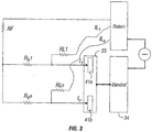
- One of the problems with "two-electrode” imaging tools is a lack of resolution to resistivity inhomogeneities in front of the pad's buttons. The reason for this phenomenon could be easily seen from FIG. 3 that shows simplified paths for the current In entering the button.
- the mandrel of the tool is denoted by 34 and two exemplary resistivity electrodes 41a and 41n are shown on a pad 55.
- the current in each of the electrodes is determined by the overall impedance R i that has been affected by the leakage impedance RL between the electrode and the return, the impedance of the fluid between the electrode R fl and the formation, the background formation impedance RF as well as the local variation of the formation resistivity ⁇ RF -the desired signal.
- R i RL ⁇ R fl + RF + ⁇ RF RL + R fl + RF + ⁇ ⁇ RF
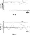
- the impedance R fl can be quite small in the presence of large standoff resulting in a quite significant leakage currents IL i . This measurement situation could lead to the pad response as demonstrated on the Fig. 4a . Shown in Fig.
- the 4a is a measured signal 101 plotted as a function of electrode number n.
- the measured signal 101 includes a large background signal and a small imaging signal component.
- the desired signal could be either poorly digitized if there is not enough dynamic range of the analog to digital converter used in the system, or could even by clipped to the full scale level 103. It should be noticed that in known tools the above-mentioned problem can not be recovered by automatic gain control, or in post-processing.
- a plurality of sensors make measurements of a parameter of interest of the earth formation.
- the signals associated with each of the sensors may be characterized as the sum of a background signal and a differential signal.
- the differential signal varies from one sensor to another and is characteristic of local variations in the parameter of interest.
- the signals at the sensors are analog measurements. In situations where the background signal is much greater than the differential signal, it is desirable to improve the dynamic range of the difference signals when the output of the sensors is part of a digital data processing system The present invention addresses this problem.
- US 4468623 discloses electrical borehole data logging in which enhancement techniques for fracture detection and alignment determination may be employed.
- US 6151555 discloses processing of seismic signals propagating through a variance cube.
- US 2005/006090 discloses electrical property a formation surrounding a borehole with a measuring-while-drilling device.
- Embodiments of the invention provide an apparatus and method as defined in the appended claims.
- FIG. 1 shows an imaging tool 10 suspended in a borehole 12, that penetrates earth formations such as 13, from a suitable cable 14 that passes over a sheave 16 mounted on drilling rig 18.
- the cable 14 includes a stress member and seven conductors for transmitting commands to the tool and for receiving data back from the tool as well as power for the tool.
- the tool 10 is raised and lowered by draw works 20.
- Electronic module 22, on the surface 23, transmits the required operating commands downhole and in return, receives data back which may be recorded on an archival storage medium of any desired type for concurrent or later processing.
- the data may be transmitted in analog or digital form.
- Data processors such as a suitable computer 24, may be provided for performing data analysis in the field in real time or the recorded data may be sent to a processing center or both for post processing of the data. Some of the data processing may also be done by a downhole computer.
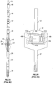
- FIG. 2a is a schematic external view of a borehole sidewall imager system.
- the tool 10 comprising the imager system includes resistivity arrays 26 and, optionally, a mud cell 30 and a circumferential acoustic televiewer 32.
- Electronics modules 28 and 38 may be located at suitable locations in the system and not necessarily in the locations indicated.
- the components may be mounted on a mandrel 34 in a conventional well-known manner.
- An orientation module 36 including a magnetometer and an accelerometer or inertial guidance system may be mounted above the imaging assemblies 26 and 32.
- the upper portion 38 of the tool 10 contains a telemetry module for sampling, digitizing and transmission of the data samples from the various components uphole to surface electronics 22 in a conventional manner. If acoustic data are acquired, they are preferably digitized, although in an alternate arrangement, the data may be retained in analog form for transmission to the surface where it is later digitized by surface electronics 22.
- each array includes measure electrodes 41a, 41b, ... 41n for injecting electrical currents into the formation, focusing electrodes 43a, 43b for horizontal focusing of the electrical currents from the measure electrodes and focusing electrodes 45a, 45b for vertical focusing of the electrical currents from the measure electrodes.
- vertical refers to the direction along the axis of the borehole and “horizontal” refers to a plane perpendicular to the vertical.
- the method of the present invention may also be used with tools that do not have the focusing electrodes.
- MWD measurement-while-drilling
- LWD logging-while-drilling
- LWT logging-while-tripping
- the sensor assembly may be used on a substantially non-rotating pad as taught in US6173793 having the same assignee as the present application.
- the sensor assembly may also be used on a non-rotating sleeve, such as that disclosed in US6247 542 .
- a slickline implementation of the invention is also possible in which the sensor assembly is conveyed downhole on a slickline, the data recorded on a suitable memory device, and retrieved for subsequent processing.
- the measured signal is dominated by the effects of the background formation impedance R f , the effects of fluid impedance R fl and the leakage currents lL i .
- the present invention is based on recognition of the fact that R f , R fl and the leakage currents are slowly varying quantities with respect to the spatial electrode position.
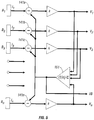
- An adaptive feed back is implemented in the front-end part of the pad, i.e., prior to digitization. This is illustrated with reference to Fig. 5 .
- V n of the electrodes 41a, 41b, 41c....41n are averaged by the averaging amplifier 151 and the output of the averaging amplifier VB is used as a negative feedback to the differential amplifiers 141a, 141b, 141c...141n, the other input to the differential amplifiers being the corresponding measured currents I 1 , I 2 , I 3 ... I n from the button electrodes.
- the output of the averaging amplifier 151 is also may also be used for further processing, saved for subsequent retrieval, or telemetered uphole as an indication of the background formation resistivity.
- V n provide a high resolution image of the formation resistivity that has an improved dynamic range over the raw measurements, and are digitized using standard methods. The image is indicative of local heterogeneities of the borehole wall. The average may be added back to the digitized filtered outputs to provide an indication of absolute formation resistivity.
- the signal 101' shows the result of using the front end feedback processing of the output 101 of the electrodes.
- the differences between the electrodes are enhanced: these differences are indicative of inhomogeneities in the resistivity of the borehole wall.
- the dynamic range is larger than in Fig. 4a .
- the measure electrodes constitute sensors and the measure currents are measurements associated with the measure electrodes.
- the analog circuitry combines the measure currents by averaging them. A difference between the averaged current and the individual measure currents forms a useful output of the system. It should be noted that the method described above could also be used with other sensor arrangements, including those without focusing electrodes or pads.
- U.S. Pat. No. 6,801,039 to Fabris et al. having the same assignee as the present invention teaches the use of a defocused electrode system that is used for determination of the resistivity of borehole fluids.
- the apparatus and method described above may be used with water-based mud (WBM) as well as with oil-based mud (OBM).
- WBM water-based mud
- OBM oil-based mud
- capacitive coupling of the electrical signals is used using, for example, the teachings of U.S. Pat. No. 6,714,014 to Evans et al. , having the same assignee as the present invention.
- the current is a modulated high frequency current that capacitively couples the electrical source on the logging tool to the formation.
- the problem of a large background signal is also encountered in other situations such as secondary recovery operations.
- the objective is to monitor the flow of hydrocarbons in a reservoir between an injection well and a production well.
- Seismic or electromagnetic sources are positioned in one borehole and a plurality of detectors are typically installed in a second well.
- the passage of energy from the sources is affected by the relative distribution of fluids in the reservoir. What is of interest are differences between the received signal at the different receivers.
- the feedback circuitry discussed above may be used to enhance the desired signal in the presence of the large background signal (the bulk properties of the earth formation between the source and the receiver).
- Yet another example is in the borehole televiewer in which an acoustic source inside a borehole is used to obtain an image of the borehole wall.
- an acoustic device to determine borehole geometry and tool standoff is disclosed in US 5638337 to Priest .
- US4463378 to Rambow displays both the amplitude and time of acoustic reflections from a borehole televiewer. While the times (and hence the borehole geometry) are relatively insensitive to the fluid in the borehole, the amplitude may be greatly affected by the attenuation of the acoustic signals within the borehole fluid.
- the apparatus and method has been described above using a wireline implementation as an example.
- the present invention can also be implemented for MWD applications.
- An example of resistivity imaging for MWD is discussed in US6600321 to Evans , having the same assignee as the present invention.
- a single electrode may be used.
- the measurement made by the single electrode at a plurality of rotational angles and a plurality of depths define a virtual array of measure electrodes, measurements of which can be processed digitally using the same principles as the analog feedback filtering described above.
- the implementation using a single electrode requires the use of an orientation sensor such as a magnetometer, and accurate estimates of depth as drilling progresses. The depth estimates may be made using, for example, the method disclosed in US6769497 to Dubinsky et al. , having the same assignee as the present invention.
- the operation of the transmitters and receivers may be done by a downhole processor and/or a surface processor. Implicit in the control and processing of the data is the use of a computer program on a suitable machine readable medium that enables the processor to perform the control and processing.
- the processing may include, for example, producing a resistivity image of the wall of the borehole using the filtered signals from the measure electrodes.
- the machine readable medium may include ROMs, EPROMs, EAROMs, Flash Memories and Optical disks.
- the term "processor" as used herein is intended to include Field Programmable Gate Arrays (FPGAs).
Landscapes
- Life Sciences & Earth Sciences (AREA)
- Engineering & Computer Science (AREA)
- Environmental & Geological Engineering (AREA)
- Geology (AREA)
- Remote Sensing (AREA)
- Physics & Mathematics (AREA)
- General Life Sciences & Earth Sciences (AREA)
- General Physics & Mathematics (AREA)
- Geophysics (AREA)
- Geophysics And Detection Of Objects (AREA)
- Investigating Or Analyzing Materials By The Use Of Electric Means (AREA)
- Measurement Of Resistance Or Impedance (AREA)
- Battery Electrode And Active Subsutance (AREA)
- Electronic Switches (AREA)
- Cold Cathode And The Manufacture (AREA)
Claims (16)
- Appareil adapté pour détecter une résistivité d'une région souterraine, l'appareil comprenant :
une pluralité d'électrodes (41a ... 41n), chaque électrode (41a ... 41n) configurée pour produire un signal (I1 ... In) indicatif de la résistivité de la région souterraine, caractérisé en ce que l'appareil comprend en outre :des circuits analogiques (38, 22) configurés pour fournir un signal de sortie (V1 ... Vn) pour chacune de la pluralité d'électrodes (41a ... 41n), chacun des signaux de sortie comprenant une différence (141a ... 141n) entre le signal provenant d'une électrode individuelle de la pluralité d'électrodes (41a ... 41n) et une moyenne (VB) de tous les signaux de la pluralité d'électrodes (41a ... 41n) ; etun convertisseur analogique-numérique qui numérise les signaux de sortie. - Appareil selon la revendication 1 comprenant en outre des circuits (38, 22) configurés pour calculer la moyenne des signaux provenant d'une pluralité d'électrodes (41a ... 41n) pour donner la moyenne.
- Appareil selon la revendication 1 comprenant en outre un processeur (24) configuré pour produire une image de la région souterraine à partir du signal de sortie pour chacune de la pluralité d'électrodes (41a ... 41n).
- Appareil selon la revendication 1 dans lequel la région souterraine comprend au moins l'un (i) d'une matrice de formation, (ii) d'un fluide de formation et (iii) d'un fluide de trou de forage.
- Appareil selon la revendication 1 dans lequel la pluralité d'électrodes (41a ... 41n) comprend des électrodes de mesure et le signal produit par chacune de la pluralité d'électrodes comprend un courant de mesure.
- Appareil selon la revendication 1 comprenant en outre un dispositif de transport configuré pour transporter l'appareil dans un trou de forage dans la région souterraine, le dispositif de transport choisi dans le groupe constitué par (i) un câble métallique, (ii) un câble lisse et (iii) un tube de forage.
- Appareil selon la revendication 6 comprenant en outre un capteur d'orientation configuré pour effectuer une mesure d'orientation.
- Appareil selon la revendication 7 dans lequel les circuits sont sur un ensemble de fond de puits, BHA, et dans lequel au moins l'un de la pluralité de capteurs est un capteur virtuel défini par la rotation du BHA.
- Appareil selon la revendication 1 dans lequel la pluralité d'électrodes (41a ... 41n) sont installées dans un premier trou de forage.
- Appareil selon la revendication 9 dans lequel la pluralité d'électrodes (41a ... 41n) sont transportées dans le premier trou de forage, l'appareil comprenant en outre une source d'énergie positionnée dans un deuxième trou de forage espacé du premier trou de forage.
- Procédé d'évaluation d'une région souterraine, le procédé comprenant :
l'acquisition, à partir d'une pluralité d'électrodes, d'une pluralité de signaux indicatifs d'une résistivité de la région souterraine, caractérisé en ce que le procédé comprend en outre :l'utilisation de circuits analogiques de fond de trou pour fournir une différence entre chacun des signaux et une moyenne de l'ensemble de la pluralité de signaux ; etl'utilisation d'un convertisseur analogique-numérique qui numérise les signaux de sortie. - Procédé selon la revendication 11 comprenant en outre la production d'une image d'une paroi d'un trou de forage dans la région souterraine.
- Procédé selon la revendication 11 dans lequel la pluralité de signaux comprend des courants de mesure indicatifs de la résistivité de la région souterraine.
- Procédé selon la revendication 11 dans lequel l'acquisition de la pluralité de signaux comprend en outre l'utilisation d'électrodes (41a ... 41n) transportées sur un dispositif de transport choisi parmi (i) un câble métallique, (ii) un câble lisse et (iii) un tube de forage.
- Procédé selon la revendication 14 comprenant en outre la définition d'au moins l'une de la pluralité d'électrodes (41a ... 41n) comme une électrode virtuelle définie par la rotation des électrodes.
- Procédé selon la revendication 14 dans lequel la pluralité de signaux sont acquis dans un premier trou de forage, les signaux résultant de l'activation d'une source d'énergie positionnée dans un deuxième trou de forage espacé du premier trou de forage.
Applications Claiming Priority (2)
| Application Number | Priority Date | Filing Date | Title |
|---|---|---|---|
| US11/201,251 US7804302B2 (en) | 2005-08-10 | 2005-08-10 | Method and apparatus for enhancing formation resistivity images obtained with downhole galvanic tools |
| PCT/US2006/030641 WO2007021622A2 (fr) | 2005-08-10 | 2006-08-04 | Procede et dispositif permettant d'ameliorer la qualite d'images de la resistivite de formations obtenues a l'aide d'outils galvaniques de fond de trou |
Publications (3)
| Publication Number | Publication Date |
|---|---|
| EP1920272A2 EP1920272A2 (fr) | 2008-05-14 |
| EP1920272A4 EP1920272A4 (fr) | 2011-10-05 |
| EP1920272B1 true EP1920272B1 (fr) | 2020-03-25 |
Family
ID=37741996
Family Applications (1)
| Application Number | Title | Priority Date | Filing Date |
|---|---|---|---|
| EP06789493.1A Ceased EP1920272B1 (fr) | 2005-08-10 | 2006-08-04 | Procédé et dispositif permettant d'améliorer la qualité d'images de la resistivité de formations obtenues à l'aide d'outils galvaniques de fond de trou |
Country Status (7)
| Country | Link |
|---|---|
| US (1) | US7804302B2 (fr) |
| EP (1) | EP1920272B1 (fr) |
| CN (1) | CN101273286A (fr) |
| BR (1) | BRPI0615006B1 (fr) |
| CA (1) | CA2618172C (fr) |
| EA (1) | EA011498B1 (fr) |
| WO (1) | WO2007021622A2 (fr) |
Families Citing this family (16)
| Publication number | Priority date | Publication date | Assignee | Title |
|---|---|---|---|---|
| US20130030708A1 (en) * | 2007-11-29 | 2013-01-31 | Stanislav Wihelm Forgang | Wellbore logging performance verification method and apparatus |
| US8174266B2 (en) * | 2008-07-23 | 2012-05-08 | Baker Hughes Incorporated | Multi-resolution borehole resistivity imaging |
| US8050865B2 (en) * | 2008-10-31 | 2011-11-01 | Baker Hughes Incorporated | System and method for measuring resistivity parameters of an earth formation |
| US8405397B2 (en) | 2010-03-18 | 2013-03-26 | Baker Hughes Incorporated | Method for mitigating leakage currents |
| AU2010358076B2 (en) * | 2010-07-30 | 2013-10-10 | Halliburton Energy Services, Inc. | High resolution downhole imaging |
| CA2876326A1 (fr) * | 2012-06-29 | 2014-01-03 | Halliburton Energy Services, Inc. | Imagerie totale a micro-impedance de tenseur |
| CN102691498B (zh) * | 2012-06-29 | 2014-11-26 | 西南石油大学 | 一种水平井随钻泥浆电参数测量仪 |
| MX348211B (es) | 2012-06-29 | 2017-06-05 | Halliburton Energy Services Inc | Generador de imagenes del pozo de perforacion de induccion axial multiple. |
| CN102720490B (zh) * | 2012-06-29 | 2014-11-26 | 西南石油大学 | 一种直井随钻钻井液油气信息测量方法及测量仪器 |
| US9121963B2 (en) | 2013-12-05 | 2015-09-01 | Baker Hughes Incorporated | Dual mode balancing in OBM resistivity imaging |
| US20170023695A1 (en) * | 2014-04-14 | 2017-01-26 | Halliburton Energy Services Inc. | Generator for laterolog tool |
| WO2016057311A1 (fr) * | 2014-10-10 | 2016-04-14 | Halliburton Energy Services, Inc. | Mesure de résistivité améliorée au moyen d'un outil galvanique |
| CN104678443A (zh) * | 2015-01-22 | 2015-06-03 | 深圳市市政设计研究院有限公司 | 一种孤石探测仪及其控制方法 |
| CN107797154B (zh) * | 2017-09-22 | 2019-04-12 | 中国石油天然气股份有限公司 | 一种电成像测井图像刻度方法及装置 |
| US10634809B2 (en) * | 2017-10-25 | 2020-04-28 | Saudi Arabian Oil Company | Water crest monitoring using electromagnetic transmissions |
| US11143779B2 (en) | 2018-04-16 | 2021-10-12 | Halliburton Energy Services, Inc. | Deconvolution-based enhancement of apparent resistivity and bed boundary identification in borehole resistivity imaging |
Family Cites Families (30)
| Publication number | Priority date | Publication date | Assignee | Title |
|---|---|---|---|---|
| CA685727A (en) | 1964-05-05 | Schlumberger Limited | Method of and apparatus for borehole logging | |
| US2769920A (en) * | 1942-07-24 | 1956-11-06 | Schlumberger Well Surv Corp | Radioactivity responsive systems for use in boreholes |
| US2930969A (en) * | 1956-05-16 | 1960-03-29 | Dresser Ind | Electrical earth borehole logging apparatus |
| US4403290A (en) * | 1971-10-13 | 1983-09-06 | Schlumberger Technology Corporation | Machine method for determining the presence and location of hydrocarbon deposits within a subsurface earth formation |
| US4282486A (en) * | 1978-12-04 | 1981-08-04 | Dresser Industries, Inc. | Dual focused resistivity logging method and apparatus with dynamic range reduction |
| US4468623A (en) * | 1981-07-30 | 1984-08-28 | Schlumberger Technology Corporation | Method and apparatus using pad carrying electrodes for electrically investigating a borehole |
| US4463378A (en) * | 1982-07-27 | 1984-07-31 | Shell Oil Company | Borehole televiewer display |
| NO308264B1 (no) * | 1994-03-22 | 2000-08-21 | Western Atlas Int Inc | Brønnloggesonde med tilnærmet sylindrisk oppstilling av piezo- elektriske akustiske transdusere for elektronisk styring og fokusering av akustiske signaler |
| US5502686A (en) * | 1994-08-01 | 1996-03-26 | Western Atlas International | Method and apparatus for imaging a borehole sidewall |
| US5638337A (en) * | 1996-08-01 | 1997-06-10 | Western Atlas International, Inc. | Method for computing borehole geometry from ultrasonic pulse echo data |
| US6607044B1 (en) * | 1997-10-27 | 2003-08-19 | Halliburton Energy Services, Inc. | Three dimensional steerable system and method for steering bit to drill borehole |
| US6173793B1 (en) * | 1998-12-18 | 2001-01-16 | Baker Hughes Incorporated | Measurement-while-drilling devices with pad mounted sensors |
| US6247542B1 (en) * | 1998-03-06 | 2001-06-19 | Baker Hughes Incorporated | Non-rotating sensor assembly for measurement-while-drilling applications |
| US6353322B1 (en) * | 1998-06-09 | 2002-03-05 | Baker Hughes Incorporated | Method for automatically calibrating resistivity well logs for effects of change in wellbore diameter and circuit drift |
| US6151555A (en) * | 1999-03-09 | 2000-11-21 | Schlumberger Technology Corporation | Seismic signal processing method and apparatus for generating a cube of variance values |
| US6348796B2 (en) * | 2000-01-11 | 2002-02-19 | Baker Hughes Incorporated | Image focusing method and apparatus for wellbore resistivity imaging |
| JP3687503B2 (ja) * | 2000-07-11 | 2005-08-24 | 株式会社村田製作所 | 電子部品の搬送装置およびこの搬送装置を用いた検査装置 |
| US6748329B2 (en) * | 2000-12-08 | 2004-06-08 | Halliburton Energy Services, Inc. | Acoustic signal processing method using array coherency |
| US6600321B2 (en) * | 2001-04-18 | 2003-07-29 | Baker Hughes Incorporated | Apparatus and method for wellbore resistivity determination and imaging using capacitive coupling |
| US6714014B2 (en) * | 2001-04-18 | 2004-03-30 | Baker Hughes Incorporated | Apparatus and method for wellbore resistivity imaging using capacitive coupling |
| US6769497B2 (en) * | 2001-06-14 | 2004-08-03 | Baker Hughes Incorporated | Use of axial accelerometer for estimation of instantaneous ROP downhole for LWD and wireline applications |
| US6984983B2 (en) * | 2002-05-31 | 2006-01-10 | Schlumberger Technology Corporation | System and method for evaluation of thinly laminated earth formations |
| US6868921B2 (en) * | 2003-01-13 | 2005-03-22 | Merlin Technology, Inc. | Boring tool tracking fundamentally based on drill string length, pitch and roll |
| US6957708B2 (en) | 2003-07-08 | 2005-10-25 | Baker Hughes Incorporated | Electrical imaging in conductive and non-conductive mud |
| US7234540B2 (en) * | 2003-08-07 | 2007-06-26 | Baker Hughes Incorporated | Gyroscopic steering tool using only a two-axis rate gyroscope and deriving the missing third axis |
| US7098664B2 (en) * | 2003-12-22 | 2006-08-29 | Halliburton Energy Services, Inc. | Multi-mode oil base mud imager |
| US7647987B2 (en) * | 2004-02-26 | 2010-01-19 | The Charles Machine Works, Inc. | Multiple antenna system for horizontal directional drilling |
| US9441476B2 (en) * | 2004-03-04 | 2016-09-13 | Halliburton Energy Services, Inc. | Multiple distributed pressure measurements |
| GB2428096B (en) * | 2004-03-04 | 2008-10-15 | Halliburton Energy Serv Inc | Multiple distributed force measurements |
| US7639016B2 (en) * | 2005-08-10 | 2009-12-29 | Baker Hughes Incorporated | Downhole multi-phase flow imager |
-
2005
- 2005-08-10 US US11/201,251 patent/US7804302B2/en active Active
-
2006
- 2006-08-04 EA EA200800461A patent/EA011498B1/ru not_active IP Right Cessation
- 2006-08-04 BR BRPI0615006-3A patent/BRPI0615006B1/pt not_active IP Right Cessation
- 2006-08-04 WO PCT/US2006/030641 patent/WO2007021622A2/fr not_active Ceased
- 2006-08-04 CN CNA2006800352095A patent/CN101273286A/zh active Pending
- 2006-08-04 EP EP06789493.1A patent/EP1920272B1/fr not_active Ceased
- 2006-08-04 CA CA2618172A patent/CA2618172C/fr not_active Expired - Fee Related
Non-Patent Citations (1)
| Title |
|---|
| None * |
Also Published As
| Publication number | Publication date |
|---|---|
| EP1920272A2 (fr) | 2008-05-14 |
| CA2618172A1 (fr) | 2007-02-22 |
| EA200800461A1 (ru) | 2008-08-29 |
| EA011498B1 (ru) | 2009-04-28 |
| WO2007021622A2 (fr) | 2007-02-22 |
| CN101273286A (zh) | 2008-09-24 |
| BRPI0615006B1 (pt) | 2018-05-22 |
| CA2618172C (fr) | 2013-11-19 |
| US20070035306A1 (en) | 2007-02-15 |
| BRPI0615006A2 (pt) | 2011-05-03 |
| US7804302B2 (en) | 2010-09-28 |
| WO2007021622A3 (fr) | 2007-05-31 |
| EP1920272A4 (fr) | 2011-10-05 |
Similar Documents
| Publication | Publication Date | Title |
|---|---|---|
| EP1922570B1 (fr) | Imageur terrestre à haute résolution de la resistivite | |
| US7665544B2 (en) | Method to improve downhole instruments | |
| US6714014B2 (en) | Apparatus and method for wellbore resistivity imaging using capacitive coupling | |
| EP1836644B1 (fr) | Inversion de donnees de journal de sondage multiscalaire et multidimensionnel et procede d'imagerie de formations profondes | |
| EP1920272B1 (fr) | Procédé et dispositif permettant d'améliorer la qualité d'images de la resistivité de formations obtenues à l'aide d'outils galvaniques de fond de trou | |
| EP1929332B1 (fr) | Imagerie des sols a resistivite a haute resolution | |
| US7696757B2 (en) | Method and apparatus for resistivity measurements using dual impedance voltage measurements | |
| US6191588B1 (en) | Methods and apparatus for imaging earth formation with a current source, a current drain, and a matrix of voltage electrodes therebetween | |
| EP1913425B1 (fr) | Imageur a haute resolution de la resistivite terrestre | |
| CA2646665C (fr) | Necessaire de catheterisation urinaire | |
| US20070279063A1 (en) | Oil-based mud resistivity imaging using resonant circuits | |
| US7432716B2 (en) | Method for compensating dielectric attenuation in downhole galvanic measurements | |
| JPH06130158A (ja) | 高分解能検層方法及び装置 |
Legal Events
| Date | Code | Title | Description |
|---|---|---|---|
| PUAI | Public reference made under article 153(3) epc to a published international application that has entered the european phase |
Free format text: ORIGINAL CODE: 0009012 |
|
| 17P | Request for examination filed |
Effective date: 20080305 |
|
| AK | Designated contracting states |
Kind code of ref document: A2 Designated state(s): FR GB |
|
| DAX | Request for extension of the european patent (deleted) | ||
| RBV | Designated contracting states (corrected) |
Designated state(s): FR GB |
|
| A4 | Supplementary search report drawn up and despatched |
Effective date: 20110902 |
|
| RIC1 | Information provided on ipc code assigned before grant |
Ipc: G01V 3/20 20060101AFI20110829BHEP Ipc: G01V 3/24 20060101ALI20110829BHEP Ipc: E21B 47/01 20060101ALI20110829BHEP |
|
| 17Q | First examination report despatched |
Effective date: 20180226 |
|
| GRAP | Despatch of communication of intention to grant a patent |
Free format text: ORIGINAL CODE: EPIDOSNIGR1 |
|
| INTG | Intention to grant announced |
Effective date: 20191017 |
|
| RIN1 | Information on inventor provided before grant (corrected) |
Inventor name: GOLD, RANDY Inventor name: FORGANG, STANISLAV W. |
|
| RAP1 | Party data changed (applicant data changed or rights of an application transferred) |
Owner name: BAKER HUGHES, A GE COMPANY, LLC |
|
| GRAS | Grant fee paid |
Free format text: ORIGINAL CODE: EPIDOSNIGR3 |
|
| GRAA | (expected) grant |
Free format text: ORIGINAL CODE: 0009210 |
|
| STAA | Information on the status of an ep patent application or granted ep patent |
Free format text: STATUS: THE PATENT HAS BEEN GRANTED |
|
| AK | Designated contracting states |
Kind code of ref document: B1 Designated state(s): FR GB |
|
| REG | Reference to a national code |
Ref country code: GB Ref legal event code: FG4D |
|
| PGFP | Annual fee paid to national office [announced via postgrant information from national office to epo] |
Ref country code: GB Payment date: 20200722 Year of fee payment: 15 Ref country code: FR Payment date: 20200721 Year of fee payment: 15 |
|
| PLBE | No opposition filed within time limit |
Free format text: ORIGINAL CODE: 0009261 |
|
| STAA | Information on the status of an ep patent application or granted ep patent |
Free format text: STATUS: NO OPPOSITION FILED WITHIN TIME LIMIT |
|
| 26N | No opposition filed |
Effective date: 20210112 |
|
| GBPC | Gb: european patent ceased through non-payment of renewal fee |
Effective date: 20210804 |
|
| PG25 | Lapsed in a contracting state [announced via postgrant information from national office to epo] |
Ref country code: GB Free format text: LAPSE BECAUSE OF NON-PAYMENT OF DUE FEES Effective date: 20210804 Ref country code: FR Free format text: LAPSE BECAUSE OF NON-PAYMENT OF DUE FEES Effective date: 20210831 |