EP1920686A2 - Agencement de liaison de conduite de fluide - Google Patents
Agencement de liaison de conduite de fluide Download PDFInfo
- Publication number
- EP1920686A2 EP1920686A2 EP07021914A EP07021914A EP1920686A2 EP 1920686 A2 EP1920686 A2 EP 1920686A2 EP 07021914 A EP07021914 A EP 07021914A EP 07021914 A EP07021914 A EP 07021914A EP 1920686 A2 EP1920686 A2 EP 1920686A2
- Authority
- EP
- European Patent Office
- Prior art keywords
- connecting sleeve
- annular
- conduit
- fluid line
- plastic
- Prior art date
- Legal status (The legal status is an assumption and is not a legal conclusion. Google has not performed a legal analysis and makes no representation as to the accuracy of the status listed.)
- Withdrawn
Links
Images

Classifications
-
- A—HUMAN NECESSITIES
- A47—FURNITURE; DOMESTIC ARTICLES OR APPLIANCES; COFFEE MILLS; SPICE MILLS; SUCTION CLEANERS IN GENERAL
- A47J—KITCHEN EQUIPMENT; COFFEE MILLS; SPICE MILLS; APPARATUS FOR MAKING BEVERAGES
- A47J31/00—Apparatus for making beverages
- A47J31/44—Parts or details or accessories of beverage-making apparatus
- A47J31/46—Dispensing spouts, pumps, drain valves or like liquid transporting devices
-
- A—HUMAN NECESSITIES
- A47—FURNITURE; DOMESTIC ARTICLES OR APPLIANCES; COFFEE MILLS; SPICE MILLS; SUCTION CLEANERS IN GENERAL
- A47J—KITCHEN EQUIPMENT; COFFEE MILLS; SPICE MILLS; APPARATUS FOR MAKING BEVERAGES
- A47J31/00—Apparatus for making beverages
- A47J31/44—Parts or details or accessories of beverage-making apparatus
- A47J31/54—Water boiling vessels in beverage making machines
- A47J31/542—Continuous-flow heaters
-
- F—MECHANICAL ENGINEERING; LIGHTING; HEATING; WEAPONS; BLASTING
- F16—ENGINEERING ELEMENTS AND UNITS; GENERAL MEASURES FOR PRODUCING AND MAINTAINING EFFECTIVE FUNCTIONING OF MACHINES OR INSTALLATIONS; THERMAL INSULATION IN GENERAL
- F16L—PIPES; JOINTS OR FITTINGS FOR PIPES; SUPPORTS FOR PIPES, CABLES OR PROTECTIVE TUBING; MEANS FOR THERMAL INSULATION IN GENERAL
- F16L37/00—Couplings of the quick-acting type
- F16L37/08—Couplings of the quick-acting type in which the connection between abutting or axially overlapping ends is maintained by locking members
- F16L37/12—Couplings of the quick-acting type in which the connection between abutting or axially overlapping ends is maintained by locking members using hooks, pawls, or other movable or insertable locking members
- F16L37/14—Joints secured by inserting between mating surfaces an element, e.g. a piece of wire, a pin, a chain
- F16L37/142—Joints secured by inserting between mating surfaces an element, e.g. a piece of wire, a pin, a chain where the securing element is inserted tangentially
- F16L37/144—Joints secured by inserting between mating surfaces an element, e.g. a piece of wire, a pin, a chain where the securing element is inserted tangentially the securing element being U-shaped
Definitions
- the invention relates to a fluid line connection arrangement according to the preamble of claim 1.
- a pipe as a first pipe is tightly connected to a housing in a bore as a second pipe.
- An end portion of the tube has mutually spaced annular or bead-shaped extensions, between which a sleeve is held.
- the sleeve has at its end faces annular recesses on which the extensions of the tube can rest.
- the sleeve has a cylindrical peripheral wall portion.
- the housing with the serving as a second line bore is a molding in which the extension of the bore an enlarged bore is formed, which merges at an annular shoulder in the serving as a second line bore.
- a holding element On a shoulder opposite, outwardly open side of the housing is an even more expanded, approximately frusto-conical hollow portion formed with an undercut on the open side, which receives a holding element.
- this is formed with a disc-shaped, perforated base side and two projecting from the edge, angled, resilient tabs with end-side tongues.
- the holding element can be with his support disc-shaped base on a rear end side of the sleeve inserted into the housing and are supported with the resilient tabs or tongues against the undercut of the frustoconical portion of the housing.
- An O-ring is positioned between the shoulder of the bore in the housing and its facing end of the sleeve.
- both this face and the bulbous extension of the tube abut the O-ring and press it against the bore in the housing to seal the fluid conduit connection assembly to the outside.
- the pipe end is preferably inserted with the O-ring, the sleeve and the retaining element in the axially open side of the housing until the resilient tabs of the retaining element spread apart behind the undercut of the housing.
- the resilient tabs are to be gripped and pressed with a tool, after which the pipe end can be pulled out of the housing with said elements.
- the retaining element is formed as a snap ring which largely encloses a circumferential groove in the sleeve and can be removed by engaging a pair of pliers in holes on the ring ends and contraction of the ring ends of the groove.
- a sealing spacer which is pressed by the end face of the sleeve against the O-ring, which, as in the second embodiment, lies in a recess of the tube adjacent to its bulbous enlargement.
- the snap ring or spring ring can also be removed only by engagement of a tool or a pair of pliers in holes at the ring ends of the groove. All embodiments include the pushed onto the pipe end sleeve, which is held at most between two bulbous extensions of the pipe end and presses with one of its faces directly or indirectly via the sealing spacer the O-ring against the shoulder of the bore in the housing to the sealing of the Fluid line connection arrangement to produce to the outside.
- no bead-shaped extension serves as a sealing element, which has a small outer diameter in relation to the mean diameter of the O-ring.
- the connected line can be a flexible plastic line or a metallic tube.
- a connecting part which may comprise a two outer connecting sleeve sections connecting line section. Furthermore, this is on each an end portion of the connected lines, a coupling sleeve mounted, which is formed inside and outside a cylindrical ring.
- the coupling sleeve may be made of metal, but also be sprayed as a rigid plastic part.
- a support tube may be inserted, on which the line can be supported when sliding the coupling sleeve.
- a locking element in the form of a spring clip is provided, which extends through the slot openings open laterally in the connecting sleeve and comes to rest on a rear annular end face of the inserted connecting sleeve.
- the slot recordings of the connecting sleeve can not only be open on the inside, but also on the outside, which makes possible an uncomplicated production of the connecting sleeve and easy handling of the spring clip.
- connection sleeve may instead be closed on the outside laterally, so that the spring clip largely disappears into the slot receivers.
- an O-ring between an annular shoulder of the connecting sleeve and the front annular end side of the connecting sleeve is enclosed in each case.
- the coupling sleeve of an annular outer tube portion of a laserstrahl barn comeen, in particular thermoplastic and an co-extruded with this annular inner tube portion of a laser beam absorbing weldable, insbesondre thermoplastic Plastic DE 20 2004 020 093.7 .
- Such a coupling sleeve is lasered onto the end portion of the conduit made of weldable, in particular thermoplastic plastic.
- a support tube is not required for a secure positive and non-positive application of the coupling sleeve on the end portion of the hose, since during assembly of the coupling sleeve on the end portion of the hose no significant forces are exerted that could deform it. Rather, the prefabricated annular coupling sleeve on the tube needs to be only provisionally accurate before it is reliably connected to this by lasers.
- the present invention is based on the particular problem, pressure and liquid-tight releasably connect flexible hose assemblies with rigid metallic leads of water heaters in coffee and espresso machines, the different materials, the high pressure and high temperature of both the metallic water heater and by the fluid line connection arrangement directed heated brewing water is taken into account. Added to this is the desired ease of assembly and - in case of service - disassembly of the fluid line connection assembly.
- the present invention is therefore an object of the invention to provide an uncomplicated, quickly assembled fluid line connection arrangement, which can be solved several times in case of need and reliably sealed together and especially for the connection of pressure and liquid densities flexible hoses with rigid metallic connecting lines of water heaters in coffee and espresso machines is provided.
- a second solution of the object consists in a combination of the features of the fluid line connection arrangement according to claim 2.
- Both solutions are based on a fluid line connection arrangement with a connecting member, which has two outer connecting sleeve portions, each of which an annular shoulder is formed and which connects a first line made of flexible plastic with a second line, wherein each on a continuous cylindrical end portion of the first line and the second conduit at a distance from one end of the first conduit and the second conduit, a coupling sleeve which is cylindrical inside and has a front annular end side and a rear annular end side, wherein each of the dacashülsenabroughe a spring clip is releasably attachable as a locking element which extends through in each case laterally open slot receivers in one of the connecting sleeve sections and at the rear annular end side of one of the connecting sleeve sections inserted Ver each of a front annular end face of the coupling sleeve portion abuts directly or indirectly on the annular shoulder of one of the kauseabroughe, each having an O-ring between the
- a combination feature further consists in that - as is known - the connection sleeve of the first flexible plastic conduit an annular outer tube portion of a laserstrahl barn comeen, in particular thermoplastic and an co-extruded with this annular inner tube portion of a laser beam absorbing weldable, especially thermoplastic plastic comprises and that the coupling sleeve is lasered onto the end portion of the first conduit made of weldable, in particular thermoplastic plastic.
- a metallic connecting sleeve is crimped onto the end portion of the first conduit instead of the lasered plastic connecting sleeve, for which purpose a support tube is inserted in the end portion in order to ensure a simple, reliable and tight crimp connection.
- both the end of the hose, ie the end portion of the first line, with the attached coupling sleeve and an attached O-ring, as well as the metallic connecting line with the soldered metallic coupling sleeve in each case in one of the two outer connecting sleeve portions of the connecting part plugged in and by means of one of the spring clips, respectively are inserted through the slot recordings in one of the connecting sleeve sections, locked.
- the O-rings take over the secure sealing function, while the spring clips absorb the pressure prevailing in the lines and in the connecting part.
- a third variant of the solution starts from a fluid line connection arrangement according to the preamble of claim 3 and comprises the combination of the features of claim 3.
- the outer diameter of the formed from the end portion of the rigid connecting line circumferential bead according to claim 4 is at least as large as the average diameter of the O-ring, on which it rests with its front end side in the assembled state of the fluid line connection arrangement in order to form annular contact zones or sealing zones on both end faces of the O-ring. According to this diameter ratio, the O-ring can be selected with a given circumferential bead.
- the minimum diameter of the circumferential bead still well suited for achieving good sealing of the fluid line connection arrangement is approximately as large as the average diameter of the O-ring, or in other words, the average diameter of the O-ring is approximately equal to the outer diameter the circumferential groove chosen. Accordingly, the outer circumference of the fluid passage connecting structure can be minimized.
- the fluid line connection arrangement according to claims 3-5 which has a metallic connecting line of a fixed or continuous heater, from the end portion of which a peripheral bead is formed by swaging, can receive a first line, which according to claim 6 a Connecting sleeve, which comprises an annular outer tube portion of a laser beam permeable, especially thermoplastic plastic and a co-extruded with this annular inner tube portion of a laser beam absorbing weldable, especially thermoplastic plastic, wherein the coupling sleeve is lasered onto the end portion of the first conduit made of weldable, in particular thermoplastic plastic.
- the laser beam absorption of the inner tube section in the production of its plastic material is specifically adjusted.
- said fluid line connection arrangement according to claims 3-5 can also accommodate in a versatile manner a first line of flexible plastic, in the end section of claim 7 a support tube is inserted, wherein a metallic coupling sleeve is crimped onto the end portion of the first line.
- the claims 8-16 include further advantageous embodiments of the fluid line connection arrangement.
- An implementation of the two connecting sleeve sections having connecting part as a plastic injection molded part according to claim 8 is particularly favorable to manufacture.
- slot holders according to claim 11 not only inside, but also laterally open, this allows easy production of the connecting sleeve and a particularly simple handling of the spring clip for locking or to release the fluid line connection.
- the coupling sleeve as provided respectively for the first conduit of flexible plastic of the fluid line connection, is cut to length by a coextruded tube comprising an inner tube and an outer tube.
- a coextruded tube comprising an inner tube and an outer tube.
- the plastic of the inner tube is advantageous simply laser-absorbing inked, whereby the other material properties of the plastic are not impaired.
- thermoplastic material of the inner tube a laser-beam-permeable plastic, are distributed as uniformly as possible in the soot particles for laser beam absorption.
- the wall thickness of the inner tube should be sufficient to ensure sufficient laser beam absorption for welding or fusion with the plastic of the tube of the first conduit of the fluid connection. According to claim 16, a wall thickness of 0.2 - 0.3 mm is sufficient.
- the coextruded tube mainly consist of laserstrahl trimurem plastic, which is not modified to absorb laser radiation.
- a flexible plastic line is connected as the first line 1 with a rigid metallic connecting line as the second line 2, which is part of an only partially indicated flow heater 3, by means of a connecting part 4 which has two opposite ends open connection sleeve sections 4a, 4b have the same shape features and are interconnected by a line section 4c.
- a connecting sleeve 5 is lasered at an end portion shortly before its connection-side end, which serves to fix the first line 1 in the connecting sleeve portion 4 a of the connecting part 4.
- the plastic coupling sleeve 5 used for this purpose is a section of a coextruded tube with an annular inner tube section and also an annular outer tube section and is cut to length from such a coextruded tube.
- the inner tube section and the outer tube section are not shown separately in FIG.
- the coupling sleeve 5 consists of a copolymer, in particular tetrafluoromethylene or hexafluoropropylene.
- the copolymer is normally laser-transparent and transparent. In this form, it forms the annular outer tube portion of the coupling sleeve.
- the plastic of the inner tube section has a carbon black content of 1 to 2 percent by weight for laser beam absorption; he is black.
- the inner tube section is positively and non-positively connected by the co-extrusion of the tube with the outer tube.
- the inner tube is sufficiently thick with a typical wall thickness of 0.25 mm to be sufficiently heated after application of the coupling sleeve 5 on the end portion of the first tube protruding tube end 1 in a tool under laser beam absorption, and welded to the inner end portion become.
- the outer tube section may have a wall thickness greater than the inner tube section in order to be mechanically resistant. Both tube sections of the connecting sleeve 5 together form an unspecified annular end face on which an O-ring 6 can abut as a sealing element.
- a connecting sleeve 7 made of metal is soldered on the metallic connecting line 2 of the water heater 3 and is thus positively and non-positively connected to the metallic connecting line 2 as the connecting sleeve 5 made of plastic with the first line. 1
- connecting sleeve sections 4a, 4b with the first line 1 as a flexible plastic line and with the second line 2 as a metallic connecting line slot receivers 9, 10 are formed from the connecting sleeve sections 4a, 4b, which are open on the inside, see Figures 1 and 2, however outside are closed laterally, see Figure 3.
- the fixed but releasable connection by inserting a respective spring clip 10 and 11, in the slot receivers 8 and 9.
- the spring clip is easily inserted with its open extended end into the associated slot receptacles 8 and 9 without tools and holds due to the wavy shape of their two substantially parallel legs axially fixed the end portion of the first and second line, the spring clip against the Pressing connection sleeve 5 and 7, respectively, and with the aid of the O-ring 6 or 8 establishes a fluid-tight connection.
- the O-ring is located on the one hand on an unspecified connection-side end face of the connecting sleeve 5 and 7 and on the other hand on a likewise not designated shoulder, on which the two connecting sleeve sections 4a and 4b connecting line section 4c in a connecting sleeve 5 and 7 receiving portion of larger inner diameter passes.
- the first embodiment according to FIG. 1 and the second embodiment according to FIG. 2 have the same effect.
- Both embodiments are characterized by straightforward, low-cost design and easy reuse in case of maintenance.
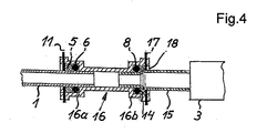
- the third embodiment of the fluid line connection arrangement shown in FIG. 4 is still significantly less expensive to manufacture.
- the outer diameter of the bead 14 is approximately the same as the average diameter of the O-ring 8, against which the bead 14 is mounted in the assembled state of the fluid line connection arrangement directly supported.
- a spring clip 17 is inserted into a slot receptacle 18 of a connecting sleeve portion 16b.
- the spring clip 17 and the slot receptacle 18 and the connecting sleeve section 1 6b are formed like the spring clip 12 and the slot receptacle 10 and the connecting sleeve section 4b of the first and second embodiments, except that they can be adapted to the larger outer diameter of the metallic connecting line 15.
- connecting part 16 with the connecting sleeve portion 16a connecting the first line 1 to the second line 15 are the same as described above for the connecting part 4 and the connecting sleeve portion 4a of the first embodiment according to FIG Reference is made.
- the latter also applies to the first line 1 with the lasered connection sleeve 5 and its function together with the O-ring 6 and the spring clip eleventh
Landscapes
- Engineering & Computer Science (AREA)
- Food Science & Technology (AREA)
- General Engineering & Computer Science (AREA)
- Mechanical Engineering (AREA)
- Quick-Acting Or Multi-Walled Pipe Joints (AREA)
Applications Claiming Priority (1)
| Application Number | Priority Date | Filing Date | Title |
|---|---|---|---|
| DE202006017177U DE202006017177U1 (de) | 2006-11-10 | 2006-11-10 | Fluidleitungsverbindungsanordnung |
Publications (2)
| Publication Number | Publication Date |
|---|---|
| EP1920686A2 true EP1920686A2 (fr) | 2008-05-14 |
| EP1920686A3 EP1920686A3 (fr) | 2012-01-04 |
Family
ID=37697751
Family Applications (2)
| Application Number | Title | Priority Date | Filing Date |
|---|---|---|---|
| EP07017699A Withdrawn EP1920685A2 (fr) | 2006-11-10 | 2007-09-11 | Agencement de liaison de conduite de fluide |
| EP07021914A Withdrawn EP1920686A3 (fr) | 2006-11-10 | 2007-11-12 | Agencement de liaison de conduite de fluide |
Family Applications Before (1)
| Application Number | Title | Priority Date | Filing Date |
|---|---|---|---|
| EP07017699A Withdrawn EP1920685A2 (fr) | 2006-11-10 | 2007-09-11 | Agencement de liaison de conduite de fluide |
Country Status (2)
| Country | Link |
|---|---|
| EP (2) | EP1920685A2 (fr) |
| DE (1) | DE202006017177U1 (fr) |
Cited By (3)
| Publication number | Priority date | Publication date | Assignee | Title |
|---|---|---|---|---|
| EP2340750A1 (fr) | 2010-01-04 | 2011-07-06 | Nestec S.A. | Agencement de couplage pour sections tubulaires en particulier dans une machine de préparation de boissons |
| CN114776903A (zh) * | 2022-05-09 | 2022-07-22 | 杨宏鹏 | 一种高压灌浆管快速连接装置 |
| WO2022194709A1 (fr) * | 2021-03-19 | 2022-09-22 | Neoperl Gmbh | Pièce d'accouplement de conduite et utilisation correspondante |
Families Citing this family (1)
| Publication number | Priority date | Publication date | Assignee | Title |
|---|---|---|---|---|
| DE102018121049A1 (de) * | 2018-08-29 | 2020-03-05 | Stiebel Eltron Gmbh & Co. Kg | Rohrverbindung von zwei miteinander medienleitend verbindbaren Rohrabschnitten und Haustechnikgerät mit einer solchen Rohrverbindung |
Family Cites Families (8)
| Publication number | Priority date | Publication date | Assignee | Title |
|---|---|---|---|---|
| FR1289274A (fr) * | 1960-05-27 | 1962-03-30 | Daimler Benz Ag | Liaison à emboîtement pour conduites tubulaires sur des véhicules, en particulier sur des voitures automobiles |
| US4753458A (en) * | 1986-08-28 | 1988-06-28 | Harvard Industries, Inc. | Quick connector assembly |
| WO1994007077A1 (fr) * | 1992-09-21 | 1994-03-31 | Proprietary Technology, Inc. | Moyen d'accouplement de raccords non filetes |
| JP3208398B2 (ja) * | 1992-11-11 | 2001-09-10 | 昭和電工株式会社 | パイプ連結具 |
| WO1996021118A1 (fr) * | 1994-12-29 | 1996-07-11 | Proprietary Technology, Inc. | Ensembles connecteurs compensant la dilatation et la contraction thermiques de conduits tubulaires |
| US5927761A (en) * | 1995-03-20 | 1999-07-27 | Proprietary Technology, Inc. | Means of coupling of non-threaded connections |
| US6550815B2 (en) * | 2001-08-14 | 2003-04-22 | Itt Manufacturing Enterprises, Inc. | Coaxial quick connector |
| DE202004020093U1 (de) * | 2004-12-29 | 2005-03-03 | Eugster/Frismag Ag | Fluidleitungsverbindungsanordnung |
-
2006
- 2006-11-10 DE DE202006017177U patent/DE202006017177U1/de not_active Expired - Lifetime
-
2007
- 2007-09-11 EP EP07017699A patent/EP1920685A2/fr not_active Withdrawn
- 2007-11-12 EP EP07021914A patent/EP1920686A3/fr not_active Withdrawn
Cited By (4)
| Publication number | Priority date | Publication date | Assignee | Title |
|---|---|---|---|---|
| EP2340750A1 (fr) | 2010-01-04 | 2011-07-06 | Nestec S.A. | Agencement de couplage pour sections tubulaires en particulier dans une machine de préparation de boissons |
| WO2022194709A1 (fr) * | 2021-03-19 | 2022-09-22 | Neoperl Gmbh | Pièce d'accouplement de conduite et utilisation correspondante |
| CN115111448A (zh) * | 2021-03-19 | 2022-09-27 | 纽珀有限公司 | 管线联接件及相应应用 |
| CN114776903A (zh) * | 2022-05-09 | 2022-07-22 | 杨宏鹏 | 一种高压灌浆管快速连接装置 |
Also Published As
| Publication number | Publication date |
|---|---|
| DE202006017177U1 (de) | 2007-01-18 |
| EP1920686A3 (fr) | 2012-01-04 |
| EP1920685A2 (fr) | 2008-05-14 |
Similar Documents
| Publication | Publication Date | Title |
|---|---|---|
| DE69004490T2 (de) | Vorrichtung zum dichten Verbinden eines Rohres mit einem Schlauch. | |
| DE4304241C2 (de) | Steckverbindung für Rohre, Schläuche oder Rundkörper | |
| DE19532356C2 (de) | Rohrverbindung | |
| DE102004014988A1 (de) | Kupplung für Kraftstoffsystemkomponenten | |
| DE3246327A1 (de) | Vorrichtung zur verbindung zweier rohrenden | |
| DE19906870C1 (de) | Anschlußarmatur mit einem Armaturkörper mit drehbarer Befestigung | |
| AT505646B1 (de) | Rohrverbindung mit einem gehäuse einer armatur | |
| WO2007045281A1 (fr) | Connexion enfichable au niveau de tubes et de tuyaux, comprenant un anneau d'encliquetage de tubes | |
| DE3017375C2 (fr) | ||
| DE29921406U1 (de) | Steckarmatur zum schnellen und lösbaren Anschluß von Druckmittel-Leitungen | |
| EP0380970A2 (fr) | Raccord de tuyaux et procédé de sa fabrication | |
| EP1920686A2 (fr) | Agencement de liaison de conduite de fluide | |
| EP1677041B1 (fr) | Dispositif de raccordement pour conduites de fluide | |
| DE9113050U1 (de) | Verbindung für Leitungsrohre | |
| DE202007018625U1 (de) | Schneidbrenner mit einem Brennerkopf, der eine auswechselbare Schneiddüse aufnimmt | |
| DE19748623B4 (de) | Preßverbindung | |
| DE9107311U1 (de) | Schweißmuffe | |
| DE3130922C1 (de) | Verschraubungssystem | |
| DE69006285T2 (de) | Verbindungsstück für Kunststoffrohre und Montageverfahren. | |
| EP1770320A1 (fr) | Raccord détachable à fiche pour des tuyaux | |
| DE19957839C1 (de) | Verbindungsstück zur Verbindung eines Schlauchendes mit einem rohrförmigen Teil | |
| DE19959067A1 (de) | Steckkupplung | |
| WO2021209351A1 (fr) | Raccord à vis pour canalisations ou tuyaux | |
| DE10107465C1 (de) | Steckverbindung für Rohrleitungen | |
| DE2717908B2 (de) | Schlauch- und/oder Rohrkupplung |
Legal Events
| Date | Code | Title | Description |
|---|---|---|---|
| PUAI | Public reference made under article 153(3) epc to a published international application that has entered the european phase |
Free format text: ORIGINAL CODE: 0009012 |
|
| AK | Designated contracting states |
Kind code of ref document: A2 Designated state(s): AT BE BG CH CY CZ DE DK EE ES FI FR GB GR HU IE IS IT LI LT LU LV MC MT NL PL PT RO SE SI SK TR |
|
| AX | Request for extension of the european patent |
Extension state: AL BA HR MK RS |
|
| RAP1 | Party data changed (applicant data changed or rights of an application transferred) |
Owner name: EUGSTER/FRISMAG AG |
|
| PUAL | Search report despatched |
Free format text: ORIGINAL CODE: 0009013 |
|
| AK | Designated contracting states |
Kind code of ref document: A3 Designated state(s): AT BE BG CH CY CZ DE DK EE ES FI FR GB GR HU IE IS IT LI LT LU LV MC MT NL PL PT RO SE SI SK TR |
|
| AX | Request for extension of the european patent |
Extension state: AL BA HR MK RS |
|
| RIC1 | Information provided on ipc code assigned before grant |
Ipc: F16L 37/088 20060101ALI20111128BHEP Ipc: F16L 37/14 20060101ALI20111128BHEP Ipc: A47J 31/54 20060101ALI20111128BHEP Ipc: A47J 31/46 20060101AFI20111128BHEP |
|
| AKY | No designation fees paid | ||
| REG | Reference to a national code |
Ref country code: DE Ref legal event code: R108 |
|
| REG | Reference to a national code |
Ref country code: DE Ref legal event code: R108 Effective date: 20120912 |
|
| STAA | Information on the status of an ep patent application or granted ep patent |
Free format text: STATUS: THE APPLICATION IS DEEMED TO BE WITHDRAWN |
|
| 18D | Application deemed to be withdrawn |
Effective date: 20120705 |