EP1920706A1 - Récepteur - Google Patents
Récepteur Download PDFInfo
- Publication number
- EP1920706A1 EP1920706A1 EP06797317A EP06797317A EP1920706A1 EP 1920706 A1 EP1920706 A1 EP 1920706A1 EP 06797317 A EP06797317 A EP 06797317A EP 06797317 A EP06797317 A EP 06797317A EP 1920706 A1 EP1920706 A1 EP 1920706A1
- Authority
- EP
- European Patent Office
- Prior art keywords
- examination
- receiving apparatus
- determiner
- time period
- unit
- Prior art date
- Legal status (The legal status is an assumption and is not a legal conclusion. Google has not performed a legal analysis and makes no representation as to the accuracy of the status listed.)
- Granted
Links
Images




Classifications
-
- A—HUMAN NECESSITIES
- A61—MEDICAL OR VETERINARY SCIENCE; HYGIENE
- A61B—DIAGNOSIS; SURGERY; IDENTIFICATION
- A61B1/00—Instruments for performing medical examinations of the interior of cavities or tubes of the body by visual or photographical inspection, e.g. endoscopes; Illuminating arrangements therefor
- A61B1/00002—Operational features of endoscopes
- A61B1/00025—Operational features of endoscopes characterised by power management
- A61B1/00036—Means for power saving, e.g. sleeping mode
-
- A—HUMAN NECESSITIES
- A61—MEDICAL OR VETERINARY SCIENCE; HYGIENE
- A61B—DIAGNOSIS; SURGERY; IDENTIFICATION
- A61B1/00—Instruments for performing medical examinations of the interior of cavities or tubes of the body by visual or photographical inspection, e.g. endoscopes; Illuminating arrangements therefor
- A61B1/04—Instruments for performing medical examinations of the interior of cavities or tubes of the body by visual or photographical inspection, e.g. endoscopes; Illuminating arrangements therefor combined with photographic or television appliances
- A61B1/041—Capsule endoscopes for imaging
-
- A—HUMAN NECESSITIES
- A61—MEDICAL OR VETERINARY SCIENCE; HYGIENE
- A61B—DIAGNOSIS; SURGERY; IDENTIFICATION
- A61B5/00—Measuring for diagnostic purposes; Identification of persons
- A61B5/07—Endoradiosondes
-
- A—HUMAN NECESSITIES
- A61—MEDICAL OR VETERINARY SCIENCE; HYGIENE
- A61B—DIAGNOSIS; SURGERY; IDENTIFICATION
- A61B1/00—Instruments for performing medical examinations of the interior of cavities or tubes of the body by visual or photographical inspection, e.g. endoscopes; Illuminating arrangements therefor
- A61B1/00002—Operational features of endoscopes
- A61B1/00011—Operational features of endoscopes characterised by signal transmission
- A61B1/00016—Operational features of endoscopes characterised by signal transmission using wireless means
-
- A—HUMAN NECESSITIES
- A61—MEDICAL OR VETERINARY SCIENCE; HYGIENE
- A61B—DIAGNOSIS; SURGERY; IDENTIFICATION
- A61B2560/00—Constructional details of operational features of apparatus; Accessories for medical measuring apparatus
- A61B2560/02—Operational features
- A61B2560/0204—Operational features of power management
- A61B2560/0209—Operational features of power management adapted for power saving
Definitions
- the present invention relates to a receiving apparatus which acquires transmission data transmitted from a body insertable device such as a capsule endoscope which is introduced into a subject body and acquires intra-subject information, for example.
- a capsule endoscope having an imaging function and a radio communication function appears in a field of endoscope.
- a patient i.e., a subject (human body)
- the capsule endoscope After being swallowed by a patient, i.e., a subject (human body), from the mouth for an observation (examination), the capsule endoscope travels through inside internal organs (body cavities) such as esophagus, stomach, and small intestine following peristaltic movements and sequentially captures images using the imaging function until naturally discharged from a living body of the patient, in other word, during an observation period.
- body cavities such as esophagus, stomach, and small intestine following peristaltic movements
- the capsule endoscope captures images in the body cavities thereby obtaining image data, and sequentially transmits the image data to an outside of the subject body via radio communication, for example, using the radio communication function.
- the image data received is accumulated in a memory inside an external receiving apparatus.
- the patient carries the receiving apparatus equipped with the radio communication function and the memory function, the patient can move freely without inconveniences even after swallowing the capsule endoscope and before discharging the same, i.e., even during the observation period.
- a doctor can display images inside the body cavities on a display unit or the like based on the image data accumulated in the memory of the receiving apparatus, and make diagnosis (see Patent Document 1, for example).
- Patent Document 1 Japanese Patent Application Laid-Open No. 2003-19111
- the receiving apparatus does not have a notifying unit to notify an end of examination. Therefore, even when the capsule endoscope stops sending electric waves due to battery exhaustion and the examination is terminated halfway, for example, the subject does not notice the end of the examination and keeps on carrying the receiving apparatus, whereby physical burden on the subject may increase.
- the power supply to a receiving unit in the receiving apparatus does not stop even after the examination terminates, whereby power is consumed in waste.
- an object of the present invention is to provide a receiving apparatus which can prevent unnecessary power consumption. Another object of the present invention is to make it possible to recognize the end of examination by the body insertable device.
- a receiving apparatus includes a receiver which receives transmission data transmitted from a body insertable device; a determiner which determines whether a predetermined condition to determine that an examination completes is satisfied or not; and a power supply controller which controls so that power supply at least to the receiver is cut according to a result of determination by the determiner.
- the receiving apparatus as set forth in claim 2 further includes a notifier which notifies that the examination completes according to the result of determination by the determiner.
- the receiver receives the transmission data transmitted from the body insertable device using a receiving antenna
- the receiving apparatus further includes a received electric-field strength detector which detects received electric-field strength of the receiving antenna, and the determiner determines that the predetermined condition to determine that the examination completes is satisfied, when a predetermined time period has passed since the examination starts, and when the received electric-field strength detected by the received electric-field strength detector during a predetermined time period is not higher than a predetermined value.
- the receiver receives image data as the transmission data from the body insertable device, and the receiving apparatus further includes an image reception detector which detects that the receiver fails to receive the image data, and the determiner determines that the predetermined condition to determine that the examination completes is satisfied, when the predetermined time period has passed since the examination starts, and when the image reception detector does not detect the reception of the image data for a predetermined time period.
- the receiver receives image data as the transmission data from the body insertable device, and the receiving apparatus further includes a color distribution detector which detects color distribution of the image data received by the receiver, and the determiner determines whether the predetermined condition to determine that the examination completes is satisfied or not based on the color distribution detected by the color distribution detector.
- the determiner regards a start of power supply to the apparatus or a first reception of the transmission data transmitted from the body insertable device by the receiver after the power supply starts, as the start of the examination, and the determiner regards as that the predetermined time period has passed, when the determiner detects that the predetermined time period has passed after counting of time starts from a start of the examination, or when the determiner detects that a number of transmission data transmitted from the body insertable device at a predetermined transmission rate reaches to a predetermined number.
- the predetermined condition to determine that the examination completes is set in advance, and the determiner determines whether the predetermined condition is satisfied or not, and cuts the power supply to the receiver, which receives the transmission data from the body insertable device, according to the result of determination, whereby an unnecessary power consumption can be prevented.
- FIGS. 1 to 7 Exemplary embodiments of a receiving apparatus according to the present invention will be described in detail below with reference to the drawings of FIGS. 1 to 7 . It should be noted that the present invention is not limited to the embodiments and that various modifications can be made without departing from the scope of the present invention.
- FIG. 1 is a schematic diagram of an overall structure of a wireless in-vivo information acquiring system.
- the wireless in-vivo information acquiring system includes a capsule endoscope as an example of a body insertable device.
- the wireless in-vivo information acquiring system includes a capsule endoscope 3 which is inserted into a subject 1, captures images inside body cavities, and transmits data such as image signals to a receiving apparatus 2, the receiving apparatus 2 which receives the image data of inside the body cavities when the image data is transmitted from the capsule endoscope 3 by radio, a display device 4 which displays images inside the body cavities based on the image signals received by the receiving apparatus 2, and a portable recording medium 5 which serves for data transfer between the receiving apparatus 2 and the display device 4.
- the receiving apparatus 2 includes a radio unit 2a which has plural receiving antennas A1 to An attached to an outer surface of the subject body 1, and a main receiving unit 2b which performs, for example, processing of radio signals received by the plural receiving antennas A1 to An.
- the radio unit 2a and the main receiving unit 2b are detachably connected via a connector or the like.
- Each of the receiving antennas A1 to An may be provided in a jacket which the subject 1 can wear, for example, and may be indirectly attached to the subject 1 when the subject 1 wears the jacket.
- the receiving antennas A1 to An may be detachable from the jacket.
- the display device 4 serves to display images such as images captured by the capsule endoscope 3 inside the body cavities.
- the display device 4 has a configuration like a workstation to display images based on the data obtained from the portable recording medium 5.
- the display device 4 may directly display the image on a Cathode Ray Tube (CRT) display, liquid crystal display, or the like.
- the display device 4 may output the image onto other media as in a printer.
- CTR Cathode Ray Tube
- the portable recording medium 5 can be attached to and detached from the main receiving unit 2b and the display device 4, and information can be retrieved from or recorded into the portable recording medium 5 while the portable recording medium 5 is attached to the main receiving unit 2b and the display device 4.
- the portable recording medium 5 is attached to the main receiving unit 2b and records data transmitted from the capsule endoscope 3 while the capsule endoscope travels in the body cavities of the subject body 1. After the capsule endoscope 3 is discharged from the subject body 1, in other words, after the imaging inside the subject body 1 is finished, the portable recording medium 5 is removed from the main receiving unit 2b and attached to the display device 4, then the display device 4 reads out the data recorded in the portable recording medium 5.
- the portable recording medium 5 including a Compact Flash (registered trademark) memory or the like transfers data between the main receiving unit 2b and the display device 4, the subject 1 can move more freely during the imaging inside the body cavities, and the time required for data transfer to the display device 4 can be shortened.
- the portable recording medium 5 is employed for data transfer between the main receiving unit 2b and the display device 4.
- a manner of data transfer is not limited thereto.
- the main receiving unit 2b may include other embedded type of recording device, such as a hard disk, and may be connected to the display device 4 by a cable or by radio transmission for data transfer.
- FIG. 2 is a block diagram of a structure of the receiving apparatus 2 according to a first embodiment.
- the radio unit 2a receives radio signals transmitted from the capsule endoscope 3 and demodulates the received radio signals into base band signals.
- the radio unit 2a includes receiving antennas A1 to An, a receiving unit 11 as a receiver which amplifies and demodulates radio signals received by the receiving antenna, which is selectively connected via switching under the control of a control unit C described later, among the receiving antennas A1 to An, and a received electric-field strength detector 12 which detects received electric-field strength of the receiving antennas A1 to An connected via switching.
- the main receiving unit 2b receives and processes the base band signals obtained after the demodulation in the radio unit 2a.
- the main receiving unit 2b includes an image processor 13 connected in a subsequent stage of the receiving unit 11, a display unit 14 which displays image data processed by the image processor 13, the portable recording medium 5, a notifying unit 15 which serves as a notifier that notifies an end of examination, the control unit C which controls each of the above mentioned elements, a power supply unit 16 which includes a battery, for example, that supplies power to the main receiving unit 2b and the radio unit 2a, and a switching unit 17 which connects the radio unit 2a and the power supply unit 16.
- the control unit C controls each elements in the receiving apparatus 2, and includes an examination completion determining unit C1 which serves as a determiner that determines that the capsule endoscope 3 swallowed by the subject 1 finishes the examination, a notification controller C2 which controls the operation of the notifying unit 15, and a power supply controller C3 which controls the power supply from the power supply unit 16 to the radio unit 2a.
- an examination completion determining unit C1 which serves as a determiner that determines that the capsule endoscope 3 swallowed by the subject 1 finishes the examination
- a notification controller C2 which controls the operation of the notifying unit 15
- a power supply controller C3 which controls the power supply from the power supply unit 16 to the radio unit 2a.
- the receiving unit 11 supplies image signals, which are base band signals obtained through the amplification and demodulation of the radio signals supplied from the receiving antennas, into the image processor 13, and supplies a signal indicating the received electric-field strength of the radio signal received by the receiving antenna to the received electric-field strength detector 12.
- the received electric-field strength detector 12 detects the received electric-field strength of the receiving antenna based on the above signal and outputs the detected strength to the main receiving unit 2b.
- the image data processed by the image processor 13 is stored in the portable recording medium 5 under the control of the control unit C, and displayed on the display unit 14 as necessary.
- the received electric-field strength signals supplied from the received electric-field strength detector 12 are taken into the control unit C.
- the examination completion determining unit C1 has an internal timer (not shown) for counting. The examination completion determining unit C1 determines that the examination starts when the power supply to the apparatus starts, for example, and activates the timer to start counting. On detecting that the count reaches a predetermined number indicating a predetermined time period has passed, the examination completion determining unit C1 determines that the predetermined time period has passes.
- the examination completion determining unit C1 may determine that the examination starts when the receiving unit 11 receives the transmission data from the capsule endoscope 3 for the first time after the power is on. Further, the examination completion determining unit C1 may determine that the predetermined time period has passed when the examination completion determining unit C1 detects that the number (number of frames) of transmission data (image data) transmitted from the capsule endoscope 3 at a predetermined transmission rate reaches a predetermined number, for example. Since the examination in the body cavities of the subject (human body) 1 with the use of the capsule endoscope 3 usually takes approximately eight hours, the predetermined time period set for the above determination on the completion of the examination may be set to eight hours, for example.
- the examination completion determining unit C1 takes in the information on the received electric-field strength as detected by the received electric-field strength detector 12.
- the examination completion determining unit C1 determines that a predetermined condition to determine that the examination completes is satisfied.
- the notifying unit 15 includes, for example, an LED, LCD, and speaker, and is controlled by the notification controller C2.
- the notification controller C2 takes in the result of determination by the examination completion determining unit C1.
- the notification controller C2 controls the operation of the notifying unit 15 to make the LED lighten, to make the LCD display a notification, or to make the speaker notify by sound, thereby notifying the user of the completion of the examination.
- the notifying unit 15 can be replaced with the display unit 14. Then, the notification controller C2 may control the display 14 to present the notification on the screen.
- the power supply controller C3 takes in the result of determination by the examination completion determining unit C1. When the result of determination satisfies the predetermined condition to determine that the examination completes, the power supply controller C3 controls the operation of the switching unit 17 and render the switching unit 17 off-state, thereby disconnect the power supply unit 16 from the radio unit 2a. Thus, the power supply controller C3 stops the power supply from the power supply unit 16 to the radio unit 2a.
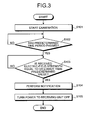
- the examination completion determining unit C1 determines that the examination has started based on the power supply to the apparatus, for example (step S101), and determines whether the count after the examination start reaches the predetermined time period (step S102).
- the examination completion determining unit C1 determines whether the received electric-field strength taken in from the received electric-field strength detector 12 during the predetermined time period is equal to or lower than the predetermined value or not (step S103).
- the examination completion determining unit C1 determines that the received electric-field strength is not higher than the predetermined value in step S103 (Yes in step S103)
- the examination completion determining unit C1 outputs the result of determination to the notification controller C2 and the power supply controller C3.
- the notification controller C2 controls the notifying unit 15 and makes the notifying unit 15 performs the notification in the above described manner (step S104).
- the power supply controller C3 controls the switching unit 17 and turns the same into the off-state, thereby cutting the power supply from the power supply unit 16 to the radio unit 2a, in particular to the receiving unit 11 which consumes large power (step S105).
- the receiving apparatus determines that the examination completes when the predetermined time period has passed after the examination starts and the received electric-field strength detected during the predetermined time period is not higher than the predetermined value, and notifies the examination completion.
- the receiving apparatus can be removed from the subject when the examination completes, whereby the physical burden on the subject can be decreased.
- the examination completion determining unit stops the power supply to the radio unit, whereby the radio unit can be prevented from consuming the power (battery) unnecessarily.
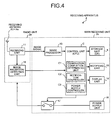
- FIG. 4 is a block diagram of a structure of the receiving apparatus 2 according to a second embodiment.
- the receiving apparatus 2 of the second embodiment is different from the receiving apparatus of the first embodiment in that the receiving apparatus of the second embodiment includes an image reception detecting unit 18 in the radio unit 2a in place of the received electric-field strength detector, and the image reception detecting unit 18 serves as an image reception detector which detects when the receiving unit 11 fails to receive the image data for a predetermined time period.
- the examination completion determining unit C1 of the second embodiment takes in the result of detection of the image data detected by the image reception detecting unit 18, and determines that a predetermined condition to determine that the examination completes is satisfied when the predetermined time period has passed after the examination starts and there is no image data reception (frame reception) for the predetermined time period.
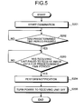
- the examination completion determining unit C1 determines whether the examination starts, and then, whether the predetermined time period has passed after the examination starts, similarly to the first embodiment (steps S201, S202).
- the examination completion determining unit C1 determines that the predetermined time period has passed after the examination starts in step S202 (Yes in step S202)
- the examination completion determining unit C1 go on to determine whether the receiving unit 11 fails to receive image data for the predetermined time period or not (step S203).
- the examination completion determining unit C1 determines that the receiving unit 11 fails to receive the image data in step S203 (Yes in step S203)
- the examination completion determining unit C1 supplies the result of determination to the notification controller C2 and the power supply controller C3.
- the notification controller C2 controls the notifying unit 15 and makes the notifying unit 15 perform the notification in the above described manner (step S204).
- the power supply controller C3 controls the switching unit 17 and turns the switching unit 17 into the off-state, thereby cutting the power supply from the power supply unit 16 to the radio unit 2a (step S205).
- the receiving apparatus determines that the examination completes when the predetermined time period has passed after the examination starts, and the receiving unit fails to receive the image data for the predetermined time period, and notifies the completion of the examination, whereby it is possible to recognize the completion of the examination by the capsule endoscope. Therefore, the receiving apparatus can be removed from the subject when the examination completes similarly to the first embodiment, and the physical burden on the subject can be reduced.
- the examination completion determining unit stops the power supply to the radio unit. Therefore, the radio unit can be prevented from consuming the power (battery) unnecessarily similarly to the first embodiment.
- FIG. 6 is a block diagram of a structure of the receiving apparatus 2 according to a third embodiment.
- the receiving apparatus 2 of the third embodiment is different from the receiving apparatus of the first embodiment in that the receiving apparatus of the third embodiment includes a color distribution detecting unit 19 in the main receiving unit 2b in place of the received electric-field detector, and the color distribution detecting unit 19 serves as a color distribution detector which detects color distribution of the image data processed by the image processor 13. Accordingly, the examination completion determining unit C1 takes in the result of detection of the color distribution of the image data by the color distribution detecting unit 19, and determines that a predetermined condition to determine that the examination completes is satisfied when the detected color distribution does not match with a predetermined color distribution.
- the color distribution detecting unit 19 detects color distribution of each image contained in a series of images processed by the image processor 13. For example, the color distribution detecting unit 19 detects an average color. Specifically, the captured image of the organ, in which the examined region resides, shows different color distribution based on the type of the organs. For example, when the average color of the processed image is pale blue, the examined region is esophagus; when the average color of the processed image is red, the examined region is stomach; when the average color of the processed image is yellow, the examined region is small intestine; and when the average color of the processed image is orange, the examined region is large intestine. It is possible to extract substantially uniform color distribution from images of each organ by detecting the average color of each frame, even when the images captured while the capsule endoscope travels through one organ contain noises.
- the examination completion determining unit C1 stores a predetermined average color corresponding to each examined region which is an examination target, and compares the average color detected by the color distribution detecting unit 19 with the stored predetermined average color, thereby determining whether the examination completes or not. In comparing the average color, the examination completion determining unit C1 may compare the processed images of the examined region based on color components constituting the average color of the processed image, for example, based on each value of a red color component R, a green color component G, and a blue color component B.
- the examination completion determining unit C1 determines whether the examination starts, similarly to the first embodiment (step S301). Then, the image processor 13 processes the received image data, and the color distribution detecting unit 19 detects the color distribution (average color) of the processed image (step S302), and further, the examination completion determining unit C1 determines whether the detected average color is identical with the stored predetermined average color or not (step S303).
- the examination completion determining unit C1 determines that the detected average color is different from the predetermined average color of the examined region in step S303 (No in step S303)
- the examination completion determining unit C1 supplies the result of determination to the notification controller C2 and the power supply controller C3.
- the notification controller C2 controls the notifying unit 15 and makes the notifying unit 15 perform the notification in the above described manner (step S304).
- the power supply controller C3 controls the switching unit 17 and turns the switching unit 17 into the off-state, thereby cutting the power supply from the power supply unit 16 to the radio unit 2a (step S305).
- the receiving apparatus determines that the examination completes when the color distribution of the processed image is different from the predetermined color distribution of the examined region, and notifies the completion of the examination, whereby it is possible to recognize the completion of the examination by the capsule endoscope. Therefore, similarly to the first and the second embodiments, the receiving apparatus can be removed from the subject when the examination completes, and the physical burden on the subject can be reduced.
- the examination completion determining unit of the third embodiment stops the power supply to the radio unit, whereby the radio unit can be prevented from consuming the power (battery) unnecessarily.
- the predetermined condition for the examination completion determining unit C1 to determine that the examination completes may be, for example, that the predetermined time period has passed since the examination starts, and that the average color detected by the color distribution detecting unit 19 is different from the predetermined average color.
- the condition may be that the average color detected by the color distribution detecting unit 19 for a predetermined time period is different from the predetermined average color.
- the receiving apparatus according to the present invention is useful for a medical observation apparatus which is introduced into an interior of a human body and employed for an observation of an examined region, and in particular, suitable for preventing unnecessary power consumption.
Landscapes
- Health & Medical Sciences (AREA)
- Life Sciences & Earth Sciences (AREA)
- Surgery (AREA)
- Engineering & Computer Science (AREA)
- General Health & Medical Sciences (AREA)
- Physics & Mathematics (AREA)
- Biomedical Technology (AREA)
- Heart & Thoracic Surgery (AREA)
- Medical Informatics (AREA)
- Molecular Biology (AREA)
- Biophysics (AREA)
- Animal Behavior & Ethology (AREA)
- Pathology (AREA)
- Public Health (AREA)
- Veterinary Medicine (AREA)
- Nuclear Medicine, Radiotherapy & Molecular Imaging (AREA)
- Optics & Photonics (AREA)
- Radiology & Medical Imaging (AREA)
- Endoscopes (AREA)
- Measurement Of The Respiration, Hearing Ability, Form, And Blood Characteristics Of Living Organisms (AREA)
Applications Claiming Priority (2)
| Application Number | Priority Date | Filing Date | Title |
|---|---|---|---|
| JP2005255496A JP4767631B2 (ja) | 2005-09-02 | 2005-09-02 | 受信装置 |
| PCT/JP2006/317375 WO2007026891A1 (fr) | 2005-09-02 | 2006-09-01 | Récepteur |
Publications (3)
| Publication Number | Publication Date |
|---|---|
| EP1920706A1 true EP1920706A1 (fr) | 2008-05-14 |
| EP1920706A4 EP1920706A4 (fr) | 2010-05-26 |
| EP1920706B1 EP1920706B1 (fr) | 2011-08-03 |
Family
ID=37808975
Family Applications (1)
| Application Number | Title | Priority Date | Filing Date |
|---|---|---|---|
| EP06797317A Not-in-force EP1920706B1 (fr) | 2005-09-02 | 2006-09-01 | Recepteur |
Country Status (6)
| Country | Link |
|---|---|
| US (1) | US8002693B2 (fr) |
| EP (1) | EP1920706B1 (fr) |
| JP (1) | JP4767631B2 (fr) |
| CN (1) | CN101252873B (fr) |
| AU (1) | AU2006285700B2 (fr) |
| WO (1) | WO2007026891A1 (fr) |
Cited By (1)
| Publication number | Priority date | Publication date | Assignee | Title |
|---|---|---|---|---|
| EP2113188A1 (fr) * | 2008-04-30 | 2009-11-04 | Given Imaging Ltd. | Système et procédés pour la détermination d'un arrêt de procédure |
Families Citing this family (8)
| Publication number | Priority date | Publication date | Assignee | Title |
|---|---|---|---|---|
| JP5137385B2 (ja) * | 2006-11-17 | 2013-02-06 | オリンパス株式会社 | カプセル型医療装置 |
| JP2008307122A (ja) * | 2007-06-12 | 2008-12-25 | Olympus Corp | 体内情報取得装置 |
| JP2009112644A (ja) * | 2007-11-08 | 2009-05-28 | Olympus Medical Systems Corp | 画像処理装置 |
| JP4705128B2 (ja) * | 2008-04-15 | 2011-06-22 | オリンパスメディカルシステムズ株式会社 | マニピュレータ |
| JP2010187756A (ja) * | 2009-02-16 | 2010-09-02 | Olympus Corp | 画像処理装置、画像処理方法および画像処理プログラム |
| JP5355169B2 (ja) * | 2009-03-24 | 2013-11-27 | オリンパス株式会社 | カプセル型医療装置およびカプセル型医療システム |
| WO2010117419A2 (fr) * | 2009-03-31 | 2010-10-14 | The Smartpill Corporation | Procédé de détermination de la sortie du corps d'une gélule ingérée |
| WO2010143721A1 (fr) * | 2009-06-12 | 2010-12-16 | オリンパスメディカルシステムズ株式会社 | Système d'acquisition de données in vivo et dispositif récepteur |
Family Cites Families (20)
| Publication number | Priority date | Publication date | Assignee | Title |
|---|---|---|---|---|
| JPH01303122A (ja) * | 1988-06-01 | 1989-12-07 | Toshiba Corp | 電子内視鏡装置 |
| JP3272450B2 (ja) * | 1993-02-23 | 2002-04-08 | 松下電器産業株式会社 | オートパワーオフ機能を備える測位装置 |
| US5778882A (en) | 1995-02-24 | 1998-07-14 | Brigham And Women's Hospital | Health monitoring system |
| JP3715692B2 (ja) * | 1995-08-30 | 2005-11-09 | キヤノン株式会社 | 画像形成装置 |
| IL122602A0 (en) * | 1997-12-15 | 1998-08-16 | Tally Eitan Zeev Pearl And Co | Energy management of a video capsule |
| US6397086B1 (en) * | 1999-06-22 | 2002-05-28 | E-Lead Electronic Co., Ltd. | Hand-free operator capable of infrared controlling a vehicle's audio stereo system |
| US6147618A (en) * | 1999-09-15 | 2000-11-14 | Ilife Systems, Inc. | Apparatus and method for reducing power consumption in physiological condition monitors |
| IL143260A (en) | 2001-05-20 | 2006-09-05 | Given Imaging Ltd | Array and method for locating an intra-body signal source |
| US20030093503A1 (en) * | 2001-09-05 | 2003-05-15 | Olympus Optical Co., Ltd. | System for controling medical instruments |
| US6924607B2 (en) * | 2002-01-07 | 2005-08-02 | Leica Microsystems Inc. | Method and apparatus for automatically shutting off a microscope |
| JP4187463B2 (ja) * | 2002-05-16 | 2008-11-26 | オリンパス株式会社 | カプセル医療装置 |
| JP4634707B2 (ja) * | 2002-10-30 | 2011-02-16 | ギブン イメージング リミテッド | 生体内装置、生体内センシング装置、生体内装置の作動方法、および自律型生体内センシング装置の作動方法 |
| JP2004234622A (ja) * | 2002-11-19 | 2004-08-19 | Seiko Instruments Inc | 生体情報計測システム |
| JP2004167163A (ja) * | 2002-11-22 | 2004-06-17 | Olympus Corp | カプセル型医療システム |
| JP3095808U (ja) * | 2003-02-10 | 2003-08-22 | 船井電機株式会社 | 光ディスク再生機能付きテレビジョン受像機 |
| JP4012097B2 (ja) | 2003-03-06 | 2007-11-21 | オリンパス株式会社 | カプセル型医療装置回収装置 |
| JP2004350963A (ja) * | 2003-05-29 | 2004-12-16 | Olympus Corp | カプセル型医療装置 |
| JP4590171B2 (ja) * | 2003-08-29 | 2010-12-01 | オリンパス株式会社 | カプセル型医療装置および当該カプセル型医療装置備えた医療装置 |
| JP3993546B2 (ja) * | 2003-09-08 | 2007-10-17 | オリンパス株式会社 | 被検体内導入装置および無線型被検体内情報取得システム |
| JP4504039B2 (ja) * | 2004-02-03 | 2010-07-14 | オリンパス株式会社 | 受信装置 |
-
2005
- 2005-09-02 JP JP2005255496A patent/JP4767631B2/ja not_active Expired - Fee Related
-
2006
- 2006-09-01 CN CN2006800321114A patent/CN101252873B/zh not_active Expired - Fee Related
- 2006-09-01 WO PCT/JP2006/317375 patent/WO2007026891A1/fr not_active Ceased
- 2006-09-01 EP EP06797317A patent/EP1920706B1/fr not_active Not-in-force
- 2006-09-01 AU AU2006285700A patent/AU2006285700B2/en not_active Ceased
- 2006-09-01 US US11/571,421 patent/US8002693B2/en not_active Expired - Fee Related
Cited By (1)
| Publication number | Priority date | Publication date | Assignee | Title |
|---|---|---|---|---|
| EP2113188A1 (fr) * | 2008-04-30 | 2009-11-04 | Given Imaging Ltd. | Système et procédés pour la détermination d'un arrêt de procédure |
Also Published As
| Publication number | Publication date |
|---|---|
| JP4767631B2 (ja) | 2011-09-07 |
| AU2006285700A1 (en) | 2007-03-08 |
| WO2007026891A1 (fr) | 2007-03-08 |
| EP1920706B1 (fr) | 2011-08-03 |
| US20090005642A1 (en) | 2009-01-01 |
| US8002693B2 (en) | 2011-08-23 |
| EP1920706A4 (fr) | 2010-05-26 |
| AU2006285700B2 (en) | 2010-06-10 |
| CN101252873A (zh) | 2008-08-27 |
| CN101252873B (zh) | 2010-10-06 |
| JP2007068568A (ja) | 2007-03-22 |
Similar Documents
| Publication | Publication Date | Title |
|---|---|---|
| US8002693B2 (en) | Receiving apparatus | |
| AU2005283435B2 (en) | Capsule-type endoscope | |
| US8131030B2 (en) | Receiving apparatus | |
| EP1922983B1 (fr) | Appareil d'observation d'image d'une cavite corporelle | |
| US20090012360A1 (en) | Antenna Unit and Receiving Apparatus Using the Same | |
| US8184148B2 (en) | Receiving apparatus | |
| CN101754714A (zh) | 接收装置 | |
| JP4823614B2 (ja) | 可搬型簡易画像表示装置及び受信システム | |
| EP1974651B1 (fr) | Récepteur | |
| EP1920703B1 (fr) | Systeme d acquisition d informations aupres d une personne examinee | |
| JP4418327B2 (ja) | 受信装置および医療装置 | |
| JP2005312769A (ja) | 受信装置および医療装置 | |
| JP2006320649A (ja) | 受信装置および受信システム | |
| JP2005103146A (ja) | 無線型被検体内情報取得装置および無線型被検体内情報取得システム | |
| JP2006080797A (ja) | 受信装置 |
Legal Events
| Date | Code | Title | Description |
|---|---|---|---|
| PUAI | Public reference made under article 153(3) epc to a published international application that has entered the european phase |
Free format text: ORIGINAL CODE: 0009012 |
|
| 17P | Request for examination filed |
Effective date: 20080227 |
|
| AK | Designated contracting states |
Kind code of ref document: A1 Designated state(s): DE FR GB |
|
| DAX | Request for extension of the european patent (deleted) | ||
| RBV | Designated contracting states (corrected) |
Designated state(s): DE FR GB |
|
| A4 | Supplementary search report drawn up and despatched |
Effective date: 20100428 |
|
| GRAP | Despatch of communication of intention to grant a patent |
Free format text: ORIGINAL CODE: EPIDOSNIGR1 |
|
| RIC1 | Information provided on ipc code assigned before grant |
Ipc: A61B 1/00 20060101AFI20110210BHEP Ipc: A61B 5/07 20060101ALI20110210BHEP |
|
| GRAS | Grant fee paid |
Free format text: ORIGINAL CODE: EPIDOSNIGR3 |
|
| GRAA | (expected) grant |
Free format text: ORIGINAL CODE: 0009210 |
|
| AK | Designated contracting states |
Kind code of ref document: B1 Designated state(s): DE FR GB |
|
| REG | Reference to a national code |
Ref country code: GB Ref legal event code: FG4D |
|
| REG | Reference to a national code |
Ref country code: DE Ref legal event code: R096 Ref document number: 602006023542 Country of ref document: DE Effective date: 20110929 |
|
| PLBE | No opposition filed within time limit |
Free format text: ORIGINAL CODE: 0009261 |
|
| STAA | Information on the status of an ep patent application or granted ep patent |
Free format text: STATUS: NO OPPOSITION FILED WITHIN TIME LIMIT |
|
| 26N | No opposition filed |
Effective date: 20120504 |
|
| GBPC | Gb: european patent ceased through non-payment of renewal fee |
Effective date: 20111103 |
|
| REG | Reference to a national code |
Ref country code: DE Ref legal event code: R097 Ref document number: 602006023542 Country of ref document: DE Effective date: 20120504 |
|
| PG25 | Lapsed in a contracting state [announced via postgrant information from national office to epo] |
Ref country code: GB Free format text: LAPSE BECAUSE OF NON-PAYMENT OF DUE FEES Effective date: 20111103 |
|
| PGFP | Annual fee paid to national office [announced via postgrant information from national office to epo] |
Ref country code: FR Payment date: 20140906 Year of fee payment: 9 |
|
| REG | Reference to a national code |
Ref country code: DE Ref legal event code: R082 Ref document number: 602006023542 Country of ref document: DE Representative=s name: WUESTHOFF & WUESTHOFF, PATENTANWAELTE PARTG MB, DE Ref country code: DE Ref legal event code: R081 Ref document number: 602006023542 Country of ref document: DE Owner name: OLYMPUS CORPORATION, JP Free format text: FORMER OWNERS: OLYMPUS CORPORATION, TOKIO/TOKYO, JP; OLYMPUS MEDICAL SYSTEMS CORP., TOKIO/TOKYO, JP |
|
| REG | Reference to a national code |
Ref country code: FR Ref legal event code: ST Effective date: 20160531 |
|
| PG25 | Lapsed in a contracting state [announced via postgrant information from national office to epo] |
Ref country code: FR Free format text: LAPSE BECAUSE OF NON-PAYMENT OF DUE FEES Effective date: 20150930 |
|
| PGFP | Annual fee paid to national office [announced via postgrant information from national office to epo] |
Ref country code: DE Payment date: 20170830 Year of fee payment: 12 |
|
| REG | Reference to a national code |
Ref country code: DE Ref legal event code: R119 Ref document number: 602006023542 Country of ref document: DE |
|
| PG25 | Lapsed in a contracting state [announced via postgrant information from national office to epo] |
Ref country code: DE Free format text: LAPSE BECAUSE OF NON-PAYMENT OF DUE FEES Effective date: 20190402 |