EP1920806A1 - Soufflerie d'entrainement pour parachutistes - Google Patents
Soufflerie d'entrainement pour parachutistes Download PDFInfo
- Publication number
- EP1920806A1 EP1920806A1 EP06769738A EP06769738A EP1920806A1 EP 1920806 A1 EP1920806 A1 EP 1920806A1 EP 06769738 A EP06769738 A EP 06769738A EP 06769738 A EP06769738 A EP 06769738A EP 1920806 A1 EP1920806 A1 EP 1920806A1
- Authority
- EP
- European Patent Office
- Prior art keywords
- wind tunnel
- area
- diffuser
- elongated
- training
- Prior art date
- Legal status (The legal status is an assumption and is not a legal conclusion. Google has not performed a legal analysis and makes no representation as to the accuracy of the status listed.)
- Withdrawn
Links
- 238000012549 training Methods 0.000 title claims abstract description 28
- 230000015572 biosynthetic process Effects 0.000 abstract description 15
- 238000005755 formation reaction Methods 0.000 description 14
- 241000264877 Hippospongia communis Species 0.000 description 9
- 239000002655 kraft paper Substances 0.000 description 6
- 239000013598 vector Substances 0.000 description 5
- 230000000694 effects Effects 0.000 description 4
- 230000005484 gravity Effects 0.000 description 4
- 230000007704 transition Effects 0.000 description 4
- 238000010276 construction Methods 0.000 description 2
- 230000007812 deficiency Effects 0.000 description 2
- 230000011514 reflex Effects 0.000 description 2
- 238000011105 stabilization Methods 0.000 description 2
- 238000009825 accumulation Methods 0.000 description 1
- 238000013459 approach Methods 0.000 description 1
- 230000003247 decreasing effect Effects 0.000 description 1
- 230000006866 deterioration Effects 0.000 description 1
- 238000011161 development Methods 0.000 description 1
- 230000005611 electricity Effects 0.000 description 1
- 238000002474 experimental method Methods 0.000 description 1
- 230000004907 flux Effects 0.000 description 1
- 238000011835 investigation Methods 0.000 description 1
- 230000009191 jumping Effects 0.000 description 1
- 238000011084 recovery Methods 0.000 description 1
- 238000000926 separation method Methods 0.000 description 1
Images
Classifications
-
- B—PERFORMING OPERATIONS; TRANSPORTING
- B64—AIRCRAFT; AVIATION; COSMONAUTICS
- B64D—EQUIPMENT FOR FITTING IN OR TO AIRCRAFT; FLIGHT SUITS; PARACHUTES; ARRANGEMENT OR MOUNTING OF POWER PLANTS OR PROPULSION TRANSMISSIONS IN AIRCRAFT
- B64D23/00—Training of parachutists
-
- A—HUMAN NECESSITIES
- A63—SPORTS; GAMES; AMUSEMENTS
- A63G—MERRY-GO-ROUNDS; SWINGS; ROCKING-HORSES; CHUTES; SWITCHBACKS; SIMILAR DEVICES FOR PUBLIC AMUSEMENT
- A63G31/00—Amusement arrangements
-
- G—PHYSICS
- G01—MEASURING; TESTING
- G01M—TESTING STATIC OR DYNAMIC BALANCE OF MACHINES OR STRUCTURES; TESTING OF STRUCTURES OR APPARATUS, NOT OTHERWISE PROVIDED FOR
- G01M9/00—Aerodynamic testing; Arrangements in or on wind tunnels
- G01M9/02—Wind tunnels
-
- A—HUMAN NECESSITIES
- A63—SPORTS; GAMES; AMUSEMENTS
- A63G—MERRY-GO-ROUNDS; SWINGS; ROCKING-HORSES; CHUTES; SWITCHBACKS; SIMILAR DEVICES FOR PUBLIC AMUSEMENT
- A63G31/00—Amusement arrangements
- A63G2031/005—Skydiving
Definitions
- This invention relates to wind tunnel systems, in particular to a training device for training parachutists and for entertainment purposes.
- the disciplines known in the field of parachuting, including freefall, can be divided into two categories: those performed at a constant rate of fall (about 50-55m / s) and those at a variable rate of fall (approx in the range of 45-70m / s).
- the first category includes freefall formation and beginner training for paratroopers (acquiring stable case skills).
- the second category includes artistic types of parachute sport: free flight, freestyle jumping and others.
- the work of a parachutist or a group of parachutists in the working area of a wind tunnel requires that the up-the body of the parachutist acting wind pressure force corresponds to the force of its weight.
- the inequality of said forces will lead to the movement of the parachutist along the axis of the stream and to leave the working area or impact safety nets, because the working area is spatially limited.
- a particularly rational solution which makes it possible to keep one or more parachutists in the work area, is that the work area is designed in the form of a diffuser.
- the speed at the entrance to the diffuser is approximately equal to the upper limit of the range of falling speeds.
- the speed at the exit of the diffuser corresponds approximately to the lower limit of the range of falling speeds.
- Self-stabilization of the body's position occurs due to the presence of a negative gradient of the velocities of the flow along the axis of the working area. That is, the body occupies such a level in the work area where the wind force acting on the body is equal to the weight of the body.
- the change in the largest cross-section or coefficient of resistance causes the transition of the body to a new, equally heavy level.
- the document [1] mentioned in the attached literature list discloses a training apparatus for training parachutists.
- This training device has a work area in the form of a diffuser with a speed range of 45-70m / s.
- the working area of the training device comprises two zones between which a net can be installed.
- the net that separates the areas is not incorporated. So the parachutists can move from the lower limit to the upper limit of the work area. If the exercises are performed in the free fall formation or for the beginner training of parachutists, the net is built in.
- the parachutists work in the upper part of the work area, in a cross-sectional area where the speed of the stream is about 50m / s.
- the workspace which is designed for the free fall formation and beginner training of paratroopers, should have a minimum length of the starting area and a minimum gradient of speed.
- the length of such a work area is relatively small (such as a distance gauge), and the opening angle is about 0.5-5 °.
- the small, oblong gradient of speed in the working area reduces the required compensation for the change in the wind congestion at different levels during the execution of the turns with the crossing of the planes.
- the small, relative length of the working area precludes increasing the boundary layer with a substantial thickness and allows a core zone to be maintained at constant rates.
- the core zone approaches the diameter of the work area. This excludes the first component of lateral force.
- the small opening angle of the working area reduces the deviation of the full aerodynamic force in the periphery of the stream, so that the second component of the lateral force is reduced.
- the workspace which is designed for the exercises for artistic types of parachute sports, should have a corresponding speed range at the inlet and outlet.
- the length of the working area should be about 2-4 distance gauges if the opening angle is 5-10 °.
- the presence of the gradient of velocities and lateral force are less critical in this case.
- Crucial is the speed, so the length of the working area and the opening angle can be assumed for the minimization of the hydraulic losses in the wind tunnel and the technological limitations.
- the said working zones can be set up in the training device in parallel or in series or be interchangeable. Particularly effective is a series arrangement of the work areas.
- Document [2] discloses a training apparatus for parachutists having a plurality of work areas, which are successively on one axis.
- the main shortcoming of said training device is that the fans are built between the working areas in the wind tunnel and that the elements that compensate for the speed field are missing.
- a necessary element of the fan that creates the pressure drop is a sleeve.
- the diameter of this sleeve in modern fans is 0.4 to 0.7 of the diameter of the duct in which the fan is installed.
- This sleeve creates a wake with a substantial width and length.
- the presence of a wake due to the sleeve of the fan in the work area makes a full training impossible. This is because when the parachutist enters the wake, where the windstorm is less than in the mainstream, it comes to overthrow the parachutist on the safety net.
- the sleeves of the fans cause significant hydraulic losses.
- the sleeves of the fans are in cross-sections whose surface coincides with the cross-sectional areas of the working areas.
- the closest prior art to the invention is a wind tunnel suitable for aerodynamic investigations [3, page 177].
- the wind tunnel contains a channel formed by the following built-in and connected elements: an inlet diffuser, a first working area, an intermediate diffuser and a second working area.
- the object of the invention is based on the development of the construction of a wind tunnel for the training of parachutists.
- the wind tunnel is to contain work areas in which current characteristics are realized, which are optimally adapted for the training of the athletes for the free fall formation and for the artistic types of the parachute sport.
- the wind tunnel should allow a simultaneous training of parachutists in both work areas.
- the wind tunnel has a channel which is formed by the following, successively installed and connected elements: an inlet diffuser, a first working area, an intermediate diffuser and a second working area.
- the wind tunnel should have working areas, which are designed as diffuser areas with different, elongated gradients of the current speed.
- the working area with the smaller, elongated speed gradient has a smaller length and the working area with the larger, elongated speed gradient has a greater length.
- the working area with the larger, elongated velocity gradient comprises at least one cross section that is perpendicular to the wind power axis. The area coincides with the area of the inlet section of the work area with the smaller, elongated velocity gradient.
- the working area with the smaller, elongated velocity gradient is installed behind the inlet diffuser.
- the working area with the larger, elongated velocity gradient is installed behind the intermediate diffuser.
- a honeycomb is installed at the outlet of the first work area.
- Safety nets are installed at the inlet of the first working area, at the inlet of the intermediate diffuser and at the outlet of the second working area.
- the cross-sectional area of the channel at the juncture of the intermediate diffuser and the second working range is chosen so that the skydiving of the parachutist from the second working area is excluded in the intermediate diffuser in the normal operation of the drive (speed in cross section about 80m / s).
- the wind tunnel according to the invention for forming parachutists comprises an inlet diffuser, a safety net, the first working area, a honeycomb, an intermediate safety net, an intermediate diffuser, a second working area and a safety net at the outlet, all of these components being arranged consecutively.
- the work areas are designed as diffuser areas with different elongated gradients of the current velocity. In this case, the working area with the smaller, elongated speed gradient has a smaller length and the working area with the larger, elongated speed gradient has a greater length.
- the diffuser workspaces allow the parachutist or groups of skydivers to be kept in the work area as he / she changes the resistance and largest cross section of the body during the movements. This is done by self-stabilization without control.
- Different elongated gradients of velocity allow to generate in each region a wind flux with characteristics optimal for the particular type of parachute sport.
- the presence of at least one cross-sectional area, the perpendicular to the wind flow axis and coinciding with the inlet cross-sectional area of the working area with the smaller, elongated velocity gradient, within the working area with the larger, elongated velocity gradient allows to obtain an equilibrium velocity in both working areas simultaneously. That is, it is possible to practice in both areas at the same time.
- the workspace with the smaller, elongated velocity gradient in front of the work area with the larger, elongated velocity gradient allows the wind power quality to be increased for parachutists who practice free fall formation (they are more sensitive to unevenness in wind power).
- This also increases the effectiveness of the intermediate diffuser, so that the unevenness of the velocity field is reduced proportionally to the square of the constriction (ratio of the area of the inlet cross section to the area of the outlet cross section).
- the honeycomb at the outlet of the first work area reduces the amount of turbulence, rotation and down-flow of the stream created by the parachutists in the first work area. This improves the quality of the stream at the inlet of the second work area and allows it to work simultaneously in both work areas.
- the safety nets increase the safety of the exercises in the wind tunnel, especially in case of failure of the drive.
- the intermediate safety net additionally compensates the velocity field of the flow at the inlet of the intermediate diffuser and accordingly at the inlet of the second working area.
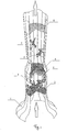
- the invention is based on a in Fig. 1 illustrated embodiment illustrated in more detail; in Fig. 1 a schematic of a wind tunnel is shown.
- the construction of the wind tunnel consists of an inlet diffuser 1, a safety net 2 at the inlet, a first working area 3, a honeycomb 4, an intermediate safety net 5, an intermediate diffuser 6, a second working area 7 and a safety net 8 at the outlet.
- the wind tunnel works as follows.
- a fan system (in Fig. 1 not shown) creates a pressure gradient, causing the air in the wind tunnel moves from bottom to top.
- inlet diffuser 1 the air is accelerated and the speed field is compensated.
- the parachutists who practice the free fall formation or beginners are trained.
- the uniformity of the current velocity field is disturbed.
- the bodies of the paratroopers create a vortex train and their movements lead to a downdraft and to the rotation of the stream.
- Honeycomb 4 reduces the amount of turbulence, rotation and downwash.
- the inter-safety network 5 partially compensates the speed field.
- the intermediate diffuser 6 the air is also accelerated and the speed field compensated.
- the parachutists are trained to practice the artistic types of parachute sport.
- the second working area is a diffuser, there is a braking of the stream and a partial recovery of the pressure. Thereafter, the air is either discharged to the outside (when the wind tunnel has an open circuit) or conveyed into the return channel, thus returning the inlet diffuser 1 back (if the wind tunnel has a closed circle). If the drive suddenly fails, the parachutists land in the first working area on the safety net at the inlet and the parachutists in the second working channel on the inter-safety net.
Landscapes
- Physics & Mathematics (AREA)
- Fluid Mechanics (AREA)
- General Physics & Mathematics (AREA)
- Engineering & Computer Science (AREA)
- Aviation & Aerospace Engineering (AREA)
- Aerodynamic Tests, Hydrodynamic Tests, Wind Tunnels, And Water Tanks (AREA)
- Devices Affording Protection Of Roads Or Walls For Sound Insulation (AREA)
- Wind Motors (AREA)
- Electrical Discharge Machining, Electrochemical Machining, And Combined Machining (AREA)
Applications Claiming Priority (2)
| Application Number | Priority Date | Filing Date | Title |
|---|---|---|---|
| UAA200506866A UA78420C2 (en) | 2005-07-12 | 2005-07-12 | Aerodynamic tunnel for training parachutists |
| PCT/UA2006/000042 WO2007008184A1 (fr) | 2005-07-12 | 2006-06-29 | Soufflerie d'entrainement pour parachutistes |
Publications (2)
| Publication Number | Publication Date |
|---|---|
| EP1920806A1 true EP1920806A1 (fr) | 2008-05-14 |
| EP1920806A4 EP1920806A4 (fr) | 2010-06-09 |
Family
ID=37637434
Family Applications (1)
| Application Number | Title | Priority Date | Filing Date |
|---|---|---|---|
| EP06769738A Withdrawn EP1920806A4 (fr) | 2005-07-12 | 2006-06-29 | Soufflerie d'entrainement pour parachutistes |
Country Status (5)
| Country | Link |
|---|---|
| US (1) | US7819664B2 (fr) |
| EP (1) | EP1920806A4 (fr) |
| RU (1) | RU2389528C2 (fr) |
| UA (1) | UA78420C2 (fr) |
| WO (1) | WO2007008184A1 (fr) |
Cited By (1)
| Publication number | Priority date | Publication date | Assignee | Title |
|---|---|---|---|---|
| CN112156481A (zh) * | 2019-11-16 | 2021-01-01 | 苏州力佳达电子科技有限公司 | 一种多功能游乐球装置 |
Families Citing this family (18)
| Publication number | Priority date | Publication date | Assignee | Title |
|---|---|---|---|---|
| RU2338570C1 (ru) * | 2007-02-21 | 2008-11-20 | Александр Николаевич Комиссаров | Устройство для развлечений |
| TR201000065A2 (tr) | 2010-01-06 | 2011-01-21 | Stm Savunma Teknoloj�Ler� M�H.Ve T�C.A.�. | Yüzey açıklıklarında akış kaynaklı rezonans sönümleyici kabin |
| RU2478526C1 (ru) * | 2011-08-10 | 2013-04-10 | Николай Николаевич Петухов | Устройство для безопасного спуска с высотных объектов |
| US9191071B2 (en) * | 2012-01-05 | 2015-11-17 | Alpha Networks Inc. | Broadband power line network device and ethernet signal coupling device thereof |
| US9045232B1 (en) * | 2013-03-14 | 2015-06-02 | Timothy A. Burke | Transportable system for simulating free fall in air |
| US9682326B2 (en) * | 2014-11-24 | 2017-06-20 | Elizabeth Wales Burroughs | Human flying apparatus |
| SE541001C2 (en) * | 2016-02-15 | 2019-02-26 | Inclined Labs AB | Wind tunnel for human flight |
| EP3601989B1 (fr) * | 2017-03-27 | 2022-01-26 | Aerodium Technologies, SIA | Tunnel aérodynamique vertical ouvert |
| US10782524B2 (en) * | 2017-06-09 | 2020-09-22 | Mark Haley | Skydiving tracker: an integrated system for flight data collection and virtual reality simulators for improving skydiving safety |
| US10537816B2 (en) * | 2017-06-30 | 2020-01-21 | Antonio Arias, IV | Body flight simulator |
| CN109011605B (zh) * | 2018-08-29 | 2020-06-19 | 南京溧水高新创业投资管理有限公司 | 一种娱乐风洞安全防护墙 |
| EP3880329B1 (fr) | 2018-11-16 | 2024-01-31 | Skyventure International (UK) Ltd. | Tunnel aérodynamique vertical à recirculation |
| CN110031182B (zh) * | 2019-05-21 | 2021-03-16 | 中国汽车工程研究院股份有限公司 | 一种产生速度梯度流场的装置及方法 |
| JP2021012349A (ja) | 2019-06-21 | 2021-02-04 | マーク ヘイリー | 自律したジェット戦闘機への移行期にパイロットの安全を改良する自動脱出技術およびスカイダイビング訓練システム |
| USD1066742S1 (en) * | 2021-08-24 | 2025-03-11 | Martin & Vleminckx Ltd. | Observation tower with movable viewing platform |
| US11891182B2 (en) * | 2023-01-23 | 2024-02-06 | Flight-1 Technologies, LLC | Multi-axis parachute and skydiving simulator |
| USD1084398S1 (en) * | 2023-03-15 | 2025-07-15 | Aerodium Technologies, Sia | Flight chamber of vertical wind tunnel |
| USD1083142S1 (en) * | 2023-07-31 | 2025-07-08 | Aerodium Technologies, Sia | Flight chamber of vertical wind tunnel |
Family Cites Families (15)
| Publication number | Priority date | Publication date | Assignee | Title |
|---|---|---|---|---|
| US3484953A (en) * | 1967-05-15 | 1969-12-23 | Ray H Norheim Jr | Apparatus for simulating free fall through air |
| US4578037A (en) * | 1981-10-20 | 1986-03-25 | Alexander Macangus | Skydiving simulator |
| JPH02152486A (ja) | 1988-12-06 | 1990-06-12 | Mitsubishi Heavy Ind Ltd | 空中遊泳模擬体験装置 |
| US5593352A (en) * | 1994-02-28 | 1997-01-14 | Methfessel; Harley A. J. | Mobile ground level skydiving apparatus |
| US5753811A (en) * | 1994-07-19 | 1998-05-19 | Inversiones Bernoulli C.A. | Aerodynamic tunnel particularly suited for entertainment purposes |
| US5655909A (en) * | 1995-03-06 | 1997-08-12 | Kitchen; William J. | Skydiving trainer windtunnel |
| US6000942A (en) * | 1996-09-17 | 1999-12-14 | Systems Technology, Inc. | Parachute flight training simulator |
| FR2766790B1 (fr) * | 1997-07-31 | 1999-10-08 | Abb Solyvent Ventec | Installation de vol libre pour la production artificielle d'un vent de sustentation |
| US6083110A (en) * | 1998-09-23 | 2000-07-04 | Sky Venture, Inc. | Vertical wind tunnel training device |
| US6813595B2 (en) * | 1999-12-27 | 2004-11-02 | Allen G. Edgar | Portable flight simulator |
| US6805558B1 (en) * | 2000-11-20 | 2004-10-19 | David Carl | Free fall and game simulator |
| KR100402933B1 (ko) * | 2001-03-22 | 2003-10-22 | 이성태 | 고공강하 모의 훈련장치 및 그를 이용한 고공강하 훈련방법 |
| RU2203718C1 (ru) * | 2002-04-02 | 2003-05-10 | Салов Дмитрий Александрович | Стенд для тренировки парашютистов |
| US7153163B2 (en) * | 2002-07-16 | 2006-12-26 | Tyco Electronics Corporation | Modular jack for ethernet applications |
| FR2843940B1 (fr) | 2002-09-04 | 2004-11-26 | Immonel | Simulateur de vol en chute libre. |
-
2005
- 2005-07-12 UA UAA200506866A patent/UA78420C2/uk unknown
-
2006
- 2006-06-29 RU RU2008105848/28A patent/RU2389528C2/ru not_active IP Right Cessation
- 2006-06-29 US US11/988,602 patent/US7819664B2/en not_active Expired - Fee Related
- 2006-06-29 EP EP06769738A patent/EP1920806A4/fr not_active Withdrawn
- 2006-06-29 WO PCT/UA2006/000042 patent/WO2007008184A1/fr not_active Ceased
Non-Patent Citations (2)
| Title |
|---|
| No further relevant documents disclosed * |
| See also references of WO2007008184A1 * |
Cited By (1)
| Publication number | Priority date | Publication date | Assignee | Title |
|---|---|---|---|---|
| CN112156481A (zh) * | 2019-11-16 | 2021-01-01 | 苏州力佳达电子科技有限公司 | 一种多功能游乐球装置 |
Also Published As
| Publication number | Publication date |
|---|---|
| UA78420C2 (en) | 2007-03-15 |
| RU2389528C2 (ru) | 2010-05-20 |
| RU2008105848A (ru) | 2010-02-20 |
| US7819664B2 (en) | 2010-10-26 |
| EP1920806A4 (fr) | 2010-06-09 |
| WO2007008184A1 (fr) | 2007-01-18 |
| US20100137069A1 (en) | 2010-06-03 |
Similar Documents
| Publication | Publication Date | Title |
|---|---|---|
| EP1920806A1 (fr) | Soufflerie d'entrainement pour parachutistes | |
| DE202005021531U1 (de) | Windkanalfreifallsimulator mit zirkulierendem Vertikalluftstrom und Seil für reduzierte Zugkraft zur Verwendung in Windtunneln und anderen Orten | |
| EP2334553B1 (fr) | Simulateur de chute libre | |
| DE202020005778U1 (de) | Strömungssimulator für Skispringer | |
| DE4007230A1 (de) | Vorrichtung zur aenderung der richtung einer luftstroemung | |
| DE202008004531U1 (de) | Von Fluid umströmte Oberfläche eines Flug- oder Strömungskörpers | |
| DE2800333A1 (de) | Haengegleiter | |
| DE1531532A1 (de) | Triebwerkslagerung an Flugzeugen | |
| EP1465806A1 (fr) | Dispositif de demonstration pour appareils de vol sportif | |
| EP0127652A1 (fr) | Structure d'avion pour decollage et atterrissage sur les pieds du pilote. | |
| EP3685890B1 (fr) | Appareil de sport de glisse commandable à l'aide de la partie supérieure du corps et / ou des bras et / ou des mains et / ou des doigts | |
| DE102013007799B3 (de) | Zusatzeinrichtung für Gleit- und Fallschirme | |
| EP0379610A1 (fr) | Aile souple en plusieurs parties pour parachute planeur, autos, motos, bateaux à moteur et autres moyens de transport | |
| DE10305973B3 (de) | Anordnung zur Reduktion von Verlusten, die mit einem starken Verdichtungsstoß verbunden sind | |
| DE102005025004B4 (de) | Verfahren und Vorrichtung zum Abmindern der Zirkulation von Hauptwirbeln in Wirbelschleppen hinter Flugzeugen | |
| DE102018132872A1 (de) | Netzanordnung, Strömungskanal mit der Netzanordnung und Abstandshalter | |
| DE3516998C2 (fr) | ||
| DE102004059474B4 (de) | Windkanal mit Strömungskollektor | |
| DE1531532C (fr) | ||
| CH475770A (de) | Schleppschirm, insbesondere zum Schleppen von skifahren | |
| DE3524019A1 (de) | Startbeschleuniger fuer flugzeuge | |
| DE1506042C (de) | Steuerbarer Fallschirm mit mehreren in der Kappe angebrachten LuftaustrittsÖffnungen | |
| DE2705194A1 (de) | Bespannung fuer drachenfluggeraete | |
| EP2801527B1 (fr) | Parapente | |
| DE102013007143A1 (de) | Fahrgeschäft |
Legal Events
| Date | Code | Title | Description |
|---|---|---|---|
| PUAI | Public reference made under article 153(3) epc to a published international application that has entered the european phase |
Free format text: ORIGINAL CODE: 0009012 |
|
| 17P | Request for examination filed |
Effective date: 20080212 |
|
| AK | Designated contracting states |
Kind code of ref document: A1 Designated state(s): AT BE BG CH CY CZ DE DK EE ES FI FR GB GR HU IE IS IT LI LT LU LV MC NL PL PT RO SE SI SK TR |
|
| A4 | Supplementary search report drawn up and despatched |
Effective date: 20100507 |
|
| GRAP | Despatch of communication of intention to grant a patent |
Free format text: ORIGINAL CODE: EPIDOSNIGR1 |
|
| DAX | Request for extension of the european patent (deleted) | ||
| GRAS | Grant fee paid |
Free format text: ORIGINAL CODE: EPIDOSNIGR3 |
|
| STAA | Information on the status of an ep patent application or granted ep patent |
Free format text: STATUS: THE APPLICATION IS DEEMED TO BE WITHDRAWN |
|
| 18D | Application deemed to be withdrawn |
Effective date: 20121127 |