EP1920838A1 - Structure en nid d abeille et substance catalytique en nid d abeille - Google Patents
Structure en nid d abeille et substance catalytique en nid d abeille Download PDFInfo
- Publication number
- EP1920838A1 EP1920838A1 EP06797144A EP06797144A EP1920838A1 EP 1920838 A1 EP1920838 A1 EP 1920838A1 EP 06797144 A EP06797144 A EP 06797144A EP 06797144 A EP06797144 A EP 06797144A EP 1920838 A1 EP1920838 A1 EP 1920838A1
- Authority
- EP
- European Patent Office
- Prior art keywords
- honeycomb
- catalyst
- cells
- structure according
- honeycomb structure
- Prior art date
- Legal status (The legal status is an assumption and is not a legal conclusion. Google has not performed a legal analysis and makes no representation as to the accuracy of the status listed.)
- Ceased
Links
Images




Classifications
-
- B—PERFORMING OPERATIONS; TRANSPORTING
- B01—PHYSICAL OR CHEMICAL PROCESSES OR APPARATUS IN GENERAL
- B01D—SEPARATION
- B01D39/00—Filtering material for liquid or gaseous fluids
- B01D39/14—Other self-supporting filtering material ; Other filtering material
- B01D39/20—Other self-supporting filtering material ; Other filtering material of inorganic material, e.g. asbestos paper, metallic filtering material of non-woven wires
- B01D39/2027—Metallic material
- B01D39/2051—Metallic foam
-
- B—PERFORMING OPERATIONS; TRANSPORTING
- B01—PHYSICAL OR CHEMICAL PROCESSES OR APPARATUS IN GENERAL
- B01J—CHEMICAL OR PHYSICAL PROCESSES, e.g. CATALYSIS OR COLLOID CHEMISTRY; THEIR RELEVANT APPARATUS
- B01J23/00—Catalysts comprising metals or metal oxides or hydroxides, not provided for in group B01J21/00
- B01J23/38—Catalysts comprising metals or metal oxides or hydroxides, not provided for in group B01J21/00 of noble metals
- B01J23/40—Catalysts comprising metals or metal oxides or hydroxides, not provided for in group B01J21/00 of noble metals of the platinum group metals
-
- B—PERFORMING OPERATIONS; TRANSPORTING
- B01—PHYSICAL OR CHEMICAL PROCESSES OR APPARATUS IN GENERAL
- B01D—SEPARATION
- B01D39/00—Filtering material for liquid or gaseous fluids
- B01D39/14—Other self-supporting filtering material ; Other filtering material
- B01D39/20—Other self-supporting filtering material ; Other filtering material of inorganic material, e.g. asbestos paper, metallic filtering material of non-woven wires
- B01D39/2068—Other inorganic materials, e.g. ceramics
- B01D39/2093—Ceramic foam
-
- B—PERFORMING OPERATIONS; TRANSPORTING
- B01—PHYSICAL OR CHEMICAL PROCESSES OR APPARATUS IN GENERAL
- B01D—SEPARATION
- B01D46/00—Filters or filtering processes specially modified for separating dispersed particles from gases or vapours
- B01D46/24—Particle separators, e.g. dust precipitators, using rigid hollow filter bodies
- B01D46/2403—Particle separators, e.g. dust precipitators, using rigid hollow filter bodies characterised by the physical shape or structure of the filtering element
- B01D46/2418—Honeycomb filters
- B01D46/2425—Honeycomb filters characterized by parameters related to the physical properties of the honeycomb structure material
-
- B—PERFORMING OPERATIONS; TRANSPORTING
- B01—PHYSICAL OR CHEMICAL PROCESSES OR APPARATUS IN GENERAL
- B01D—SEPARATION
- B01D46/00—Filters or filtering processes specially modified for separating dispersed particles from gases or vapours
- B01D46/24—Particle separators, e.g. dust precipitators, using rigid hollow filter bodies
- B01D46/2403—Particle separators, e.g. dust precipitators, using rigid hollow filter bodies characterised by the physical shape or structure of the filtering element
- B01D46/2418—Honeycomb filters
- B01D46/2425—Honeycomb filters characterized by parameters related to the physical properties of the honeycomb structure material
- B01D46/2429—Honeycomb filters characterized by parameters related to the physical properties of the honeycomb structure material of the honeycomb walls or cells
-
- B—PERFORMING OPERATIONS; TRANSPORTING
- B01—PHYSICAL OR CHEMICAL PROCESSES OR APPARATUS IN GENERAL
- B01D—SEPARATION
- B01D46/00—Filters or filtering processes specially modified for separating dispersed particles from gases or vapours
- B01D46/24—Particle separators, e.g. dust precipitators, using rigid hollow filter bodies
- B01D46/2403—Particle separators, e.g. dust precipitators, using rigid hollow filter bodies characterised by the physical shape or structure of the filtering element
- B01D46/2418—Honeycomb filters
- B01D46/2425—Honeycomb filters characterized by parameters related to the physical properties of the honeycomb structure material
- B01D46/24491—Porosity
-
- B—PERFORMING OPERATIONS; TRANSPORTING
- B01—PHYSICAL OR CHEMICAL PROCESSES OR APPARATUS IN GENERAL
- B01D—SEPARATION
- B01D46/00—Filters or filtering processes specially modified for separating dispersed particles from gases or vapours
- B01D46/24—Particle separators, e.g. dust precipitators, using rigid hollow filter bodies
- B01D46/2403—Particle separators, e.g. dust precipitators, using rigid hollow filter bodies characterised by the physical shape or structure of the filtering element
- B01D46/2418—Honeycomb filters
- B01D46/2425—Honeycomb filters characterized by parameters related to the physical properties of the honeycomb structure material
- B01D46/24492—Pore diameter
-
- B—PERFORMING OPERATIONS; TRANSPORTING
- B01—PHYSICAL OR CHEMICAL PROCESSES OR APPARATUS IN GENERAL
- B01D—SEPARATION
- B01D46/00—Filters or filtering processes specially modified for separating dispersed particles from gases or vapours
- B01D46/24—Particle separators, e.g. dust precipitators, using rigid hollow filter bodies
- B01D46/2403—Particle separators, e.g. dust precipitators, using rigid hollow filter bodies characterised by the physical shape or structure of the filtering element
- B01D46/2418—Honeycomb filters
- B01D46/2425—Honeycomb filters characterized by parameters related to the physical properties of the honeycomb structure material
- B01D46/24494—Thermal expansion coefficient, heat capacity or thermal conductivity
-
- B—PERFORMING OPERATIONS; TRANSPORTING
- B01—PHYSICAL OR CHEMICAL PROCESSES OR APPARATUS IN GENERAL
- B01D—SEPARATION
- B01D46/00—Filters or filtering processes specially modified for separating dispersed particles from gases or vapours
- B01D46/24—Particle separators, e.g. dust precipitators, using rigid hollow filter bodies
- B01D46/2403—Particle separators, e.g. dust precipitators, using rigid hollow filter bodies characterised by the physical shape or structure of the filtering element
- B01D46/2418—Honeycomb filters
- B01D46/2451—Honeycomb filters characterized by the geometrical structure, shape, pattern or configuration or parameters related to the geometry of the structure
- B01D46/2455—Honeycomb filters characterized by the geometrical structure, shape, pattern or configuration or parameters related to the geometry of the structure of the whole honeycomb or segments
-
- B—PERFORMING OPERATIONS; TRANSPORTING
- B01—PHYSICAL OR CHEMICAL PROCESSES OR APPARATUS IN GENERAL
- B01D—SEPARATION
- B01D46/00—Filters or filtering processes specially modified for separating dispersed particles from gases or vapours
- B01D46/24—Particle separators, e.g. dust precipitators, using rigid hollow filter bodies
- B01D46/2403—Particle separators, e.g. dust precipitators, using rigid hollow filter bodies characterised by the physical shape or structure of the filtering element
- B01D46/2418—Honeycomb filters
- B01D46/2451—Honeycomb filters characterized by the geometrical structure, shape, pattern or configuration or parameters related to the geometry of the structure
- B01D46/247—Honeycomb filters characterized by the geometrical structure, shape, pattern or configuration or parameters related to the geometry of the structure of the cells
-
- B—PERFORMING OPERATIONS; TRANSPORTING
- B01—PHYSICAL OR CHEMICAL PROCESSES OR APPARATUS IN GENERAL
- B01D—SEPARATION
- B01D46/00—Filters or filtering processes specially modified for separating dispersed particles from gases or vapours
- B01D46/24—Particle separators, e.g. dust precipitators, using rigid hollow filter bodies
- B01D46/2403—Particle separators, e.g. dust precipitators, using rigid hollow filter bodies characterised by the physical shape or structure of the filtering element
- B01D46/2418—Honeycomb filters
- B01D46/2451—Honeycomb filters characterized by the geometrical structure, shape, pattern or configuration or parameters related to the geometry of the structure
- B01D46/2474—Honeycomb filters characterized by the geometrical structure, shape, pattern or configuration or parameters related to the geometry of the structure of the walls along the length of the honeycomb
-
- B—PERFORMING OPERATIONS; TRANSPORTING
- B01—PHYSICAL OR CHEMICAL PROCESSES OR APPARATUS IN GENERAL
- B01D—SEPARATION
- B01D46/00—Filters or filtering processes specially modified for separating dispersed particles from gases or vapours
- B01D46/24—Particle separators, e.g. dust precipitators, using rigid hollow filter bodies
- B01D46/2403—Particle separators, e.g. dust precipitators, using rigid hollow filter bodies characterised by the physical shape or structure of the filtering element
- B01D46/2418—Honeycomb filters
- B01D46/2451—Honeycomb filters characterized by the geometrical structure, shape, pattern or configuration or parameters related to the geometry of the structure
- B01D46/2482—Thickness, height, width, length or diameter
-
- B—PERFORMING OPERATIONS; TRANSPORTING
- B01—PHYSICAL OR CHEMICAL PROCESSES OR APPARATUS IN GENERAL
- B01D—SEPARATION
- B01D46/00—Filters or filtering processes specially modified for separating dispersed particles from gases or vapours
- B01D46/24—Particle separators, e.g. dust precipitators, using rigid hollow filter bodies
- B01D46/2403—Particle separators, e.g. dust precipitators, using rigid hollow filter bodies characterised by the physical shape or structure of the filtering element
- B01D46/2418—Honeycomb filters
- B01D46/2451—Honeycomb filters characterized by the geometrical structure, shape, pattern or configuration or parameters related to the geometry of the structure
- B01D46/2484—Cell density, area or aspect ratio
-
- B—PERFORMING OPERATIONS; TRANSPORTING
- B01—PHYSICAL OR CHEMICAL PROCESSES OR APPARATUS IN GENERAL
- B01D—SEPARATION
- B01D46/00—Filters or filtering processes specially modified for separating dispersed particles from gases or vapours
- B01D46/24—Particle separators, e.g. dust precipitators, using rigid hollow filter bodies
- B01D46/2403—Particle separators, e.g. dust precipitators, using rigid hollow filter bodies characterised by the physical shape or structure of the filtering element
- B01D46/2418—Honeycomb filters
- B01D46/2498—The honeycomb filter being defined by mathematical relationships
-
- B—PERFORMING OPERATIONS; TRANSPORTING
- B01—PHYSICAL OR CHEMICAL PROCESSES OR APPARATUS IN GENERAL
- B01J—CHEMICAL OR PHYSICAL PROCESSES, e.g. CATALYSIS OR COLLOID CHEMISTRY; THEIR RELEVANT APPARATUS
- B01J23/00—Catalysts comprising metals or metal oxides or hydroxides, not provided for in group B01J21/00
- B01J23/38—Catalysts comprising metals or metal oxides or hydroxides, not provided for in group B01J21/00 of noble metals
- B01J23/54—Catalysts comprising metals or metal oxides or hydroxides, not provided for in group B01J21/00 of noble metals combined with metals, oxides or hydroxides provided for in groups B01J23/02 - B01J23/36
- B01J23/56—Platinum group metals
- B01J23/63—Platinum group metals with rare earths or actinides
-
- B—PERFORMING OPERATIONS; TRANSPORTING
- B01—PHYSICAL OR CHEMICAL PROCESSES OR APPARATUS IN GENERAL
- B01J—CHEMICAL OR PHYSICAL PROCESSES, e.g. CATALYSIS OR COLLOID CHEMISTRY; THEIR RELEVANT APPARATUS
- B01J35/00—Catalysts, in general, characterised by their form or physical properties
- B01J35/50—Catalysts, in general, characterised by their form or physical properties characterised by their shape or configuration
- B01J35/56—Foraminous structures having flow-through passages or channels, e.g. grids or three-dimensional [3D] monoliths
- B01J35/57—Honeycombs
-
- B—PERFORMING OPERATIONS; TRANSPORTING
- B01—PHYSICAL OR CHEMICAL PROCESSES OR APPARATUS IN GENERAL
- B01J—CHEMICAL OR PHYSICAL PROCESSES, e.g. CATALYSIS OR COLLOID CHEMISTRY; THEIR RELEVANT APPARATUS
- B01J37/00—Processes, in general, for preparing catalysts; Processes, in general, for activation of catalysts
- B01J37/02—Impregnation, coating or precipitation
- B01J37/0215—Coating
-
- C—CHEMISTRY; METALLURGY
- C04—CEMENTS; CONCRETE; ARTIFICIAL STONE; CERAMICS; REFRACTORIES
- C04B—LIME, MAGNESIA; SLAG; CEMENTS; COMPOSITIONS THEREOF, e.g. MORTARS, CONCRETE OR LIKE BUILDING MATERIALS; ARTIFICIAL STONE; CERAMICS; REFRACTORIES; TREATMENT OF NATURAL STONE
- C04B35/00—Shaped ceramic products characterised by their composition; Ceramics compositions; Processing powders of inorganic compounds preparatory to the manufacturing of ceramic products
- C04B35/01—Shaped ceramic products characterised by their composition; Ceramics compositions; Processing powders of inorganic compounds preparatory to the manufacturing of ceramic products based on oxide ceramics
- C04B35/10—Shaped ceramic products characterised by their composition; Ceramics compositions; Processing powders of inorganic compounds preparatory to the manufacturing of ceramic products based on oxide ceramics based on aluminium oxide
-
- C—CHEMISTRY; METALLURGY
- C04—CEMENTS; CONCRETE; ARTIFICIAL STONE; CERAMICS; REFRACTORIES
- C04B—LIME, MAGNESIA; SLAG; CEMENTS; COMPOSITIONS THEREOF, e.g. MORTARS, CONCRETE OR LIKE BUILDING MATERIALS; ARTIFICIAL STONE; CERAMICS; REFRACTORIES; TREATMENT OF NATURAL STONE
- C04B35/00—Shaped ceramic products characterised by their composition; Ceramics compositions; Processing powders of inorganic compounds preparatory to the manufacturing of ceramic products
- C04B35/01—Shaped ceramic products characterised by their composition; Ceramics compositions; Processing powders of inorganic compounds preparatory to the manufacturing of ceramic products based on oxide ceramics
- C04B35/14—Shaped ceramic products characterised by their composition; Ceramics compositions; Processing powders of inorganic compounds preparatory to the manufacturing of ceramic products based on oxide ceramics based on silica
-
- C—CHEMISTRY; METALLURGY
- C04—CEMENTS; CONCRETE; ARTIFICIAL STONE; CERAMICS; REFRACTORIES
- C04B—LIME, MAGNESIA; SLAG; CEMENTS; COMPOSITIONS THEREOF, e.g. MORTARS, CONCRETE OR LIKE BUILDING MATERIALS; ARTIFICIAL STONE; CERAMICS; REFRACTORIES; TREATMENT OF NATURAL STONE
- C04B35/00—Shaped ceramic products characterised by their composition; Ceramics compositions; Processing powders of inorganic compounds preparatory to the manufacturing of ceramic products
- C04B35/01—Shaped ceramic products characterised by their composition; Ceramics compositions; Processing powders of inorganic compounds preparatory to the manufacturing of ceramic products based on oxide ceramics
- C04B35/16—Shaped ceramic products characterised by their composition; Ceramics compositions; Processing powders of inorganic compounds preparatory to the manufacturing of ceramic products based on oxide ceramics based on silicates other than clay
- C04B35/18—Shaped ceramic products characterised by their composition; Ceramics compositions; Processing powders of inorganic compounds preparatory to the manufacturing of ceramic products based on oxide ceramics based on silicates other than clay rich in aluminium oxide
- C04B35/185—Mullite 3Al2O3-2SiO2
-
- C—CHEMISTRY; METALLURGY
- C04—CEMENTS; CONCRETE; ARTIFICIAL STONE; CERAMICS; REFRACTORIES
- C04B—LIME, MAGNESIA; SLAG; CEMENTS; COMPOSITIONS THEREOF, e.g. MORTARS, CONCRETE OR LIKE BUILDING MATERIALS; ARTIFICIAL STONE; CERAMICS; REFRACTORIES; TREATMENT OF NATURAL STONE
- C04B35/00—Shaped ceramic products characterised by their composition; Ceramics compositions; Processing powders of inorganic compounds preparatory to the manufacturing of ceramic products
- C04B35/01—Shaped ceramic products characterised by their composition; Ceramics compositions; Processing powders of inorganic compounds preparatory to the manufacturing of ceramic products based on oxide ceramics
- C04B35/16—Shaped ceramic products characterised by their composition; Ceramics compositions; Processing powders of inorganic compounds preparatory to the manufacturing of ceramic products based on oxide ceramics based on silicates other than clay
- C04B35/18—Shaped ceramic products characterised by their composition; Ceramics compositions; Processing powders of inorganic compounds preparatory to the manufacturing of ceramic products based on oxide ceramics based on silicates other than clay rich in aluminium oxide
- C04B35/195—Alkaline earth aluminosilicates, e.g. cordierite or anorthite
-
- C—CHEMISTRY; METALLURGY
- C04—CEMENTS; CONCRETE; ARTIFICIAL STONE; CERAMICS; REFRACTORIES
- C04B—LIME, MAGNESIA; SLAG; CEMENTS; COMPOSITIONS THEREOF, e.g. MORTARS, CONCRETE OR LIKE BUILDING MATERIALS; ARTIFICIAL STONE; CERAMICS; REFRACTORIES; TREATMENT OF NATURAL STONE
- C04B35/00—Shaped ceramic products characterised by their composition; Ceramics compositions; Processing powders of inorganic compounds preparatory to the manufacturing of ceramic products
- C04B35/01—Shaped ceramic products characterised by their composition; Ceramics compositions; Processing powders of inorganic compounds preparatory to the manufacturing of ceramic products based on oxide ceramics
- C04B35/46—Shaped ceramic products characterised by their composition; Ceramics compositions; Processing powders of inorganic compounds preparatory to the manufacturing of ceramic products based on oxide ceramics based on titanium oxides or titanates
-
- C—CHEMISTRY; METALLURGY
- C04—CEMENTS; CONCRETE; ARTIFICIAL STONE; CERAMICS; REFRACTORIES
- C04B—LIME, MAGNESIA; SLAG; CEMENTS; COMPOSITIONS THEREOF, e.g. MORTARS, CONCRETE OR LIKE BUILDING MATERIALS; ARTIFICIAL STONE; CERAMICS; REFRACTORIES; TREATMENT OF NATURAL STONE
- C04B35/00—Shaped ceramic products characterised by their composition; Ceramics compositions; Processing powders of inorganic compounds preparatory to the manufacturing of ceramic products
- C04B35/01—Shaped ceramic products characterised by their composition; Ceramics compositions; Processing powders of inorganic compounds preparatory to the manufacturing of ceramic products based on oxide ceramics
- C04B35/46—Shaped ceramic products characterised by their composition; Ceramics compositions; Processing powders of inorganic compounds preparatory to the manufacturing of ceramic products based on oxide ceramics based on titanium oxides or titanates
- C04B35/462—Shaped ceramic products characterised by their composition; Ceramics compositions; Processing powders of inorganic compounds preparatory to the manufacturing of ceramic products based on oxide ceramics based on titanium oxides or titanates based on titanates
- C04B35/478—Shaped ceramic products characterised by their composition; Ceramics compositions; Processing powders of inorganic compounds preparatory to the manufacturing of ceramic products based on oxide ceramics based on titanium oxides or titanates based on titanates based on aluminium titanates
-
- C—CHEMISTRY; METALLURGY
- C04—CEMENTS; CONCRETE; ARTIFICIAL STONE; CERAMICS; REFRACTORIES
- C04B—LIME, MAGNESIA; SLAG; CEMENTS; COMPOSITIONS THEREOF, e.g. MORTARS, CONCRETE OR LIKE BUILDING MATERIALS; ARTIFICIAL STONE; CERAMICS; REFRACTORIES; TREATMENT OF NATURAL STONE
- C04B35/00—Shaped ceramic products characterised by their composition; Ceramics compositions; Processing powders of inorganic compounds preparatory to the manufacturing of ceramic products
- C04B35/515—Shaped ceramic products characterised by their composition; Ceramics compositions; Processing powders of inorganic compounds preparatory to the manufacturing of ceramic products based on non-oxide ceramics
- C04B35/56—Shaped ceramic products characterised by their composition; Ceramics compositions; Processing powders of inorganic compounds preparatory to the manufacturing of ceramic products based on non-oxide ceramics based on carbides or oxycarbides
- C04B35/565—Shaped ceramic products characterised by their composition; Ceramics compositions; Processing powders of inorganic compounds preparatory to the manufacturing of ceramic products based on non-oxide ceramics based on carbides or oxycarbides based on silicon carbide
-
- C—CHEMISTRY; METALLURGY
- C04—CEMENTS; CONCRETE; ARTIFICIAL STONE; CERAMICS; REFRACTORIES
- C04B—LIME, MAGNESIA; SLAG; CEMENTS; COMPOSITIONS THEREOF, e.g. MORTARS, CONCRETE OR LIKE BUILDING MATERIALS; ARTIFICIAL STONE; CERAMICS; REFRACTORIES; TREATMENT OF NATURAL STONE
- C04B35/00—Shaped ceramic products characterised by their composition; Ceramics compositions; Processing powders of inorganic compounds preparatory to the manufacturing of ceramic products
- C04B35/515—Shaped ceramic products characterised by their composition; Ceramics compositions; Processing powders of inorganic compounds preparatory to the manufacturing of ceramic products based on non-oxide ceramics
- C04B35/58—Shaped ceramic products characterised by their composition; Ceramics compositions; Processing powders of inorganic compounds preparatory to the manufacturing of ceramic products based on non-oxide ceramics based on borides, nitrides, i.e. nitrides, oxynitrides, carbonitrides or oxycarbonitrides or silicides
- C04B35/584—Shaped ceramic products characterised by their composition; Ceramics compositions; Processing powders of inorganic compounds preparatory to the manufacturing of ceramic products based on non-oxide ceramics based on borides, nitrides, i.e. nitrides, oxynitrides, carbonitrides or oxycarbonitrides or silicides based on silicon nitride
-
- C—CHEMISTRY; METALLURGY
- C04—CEMENTS; CONCRETE; ARTIFICIAL STONE; CERAMICS; REFRACTORIES
- C04B—LIME, MAGNESIA; SLAG; CEMENTS; COMPOSITIONS THEREOF, e.g. MORTARS, CONCRETE OR LIKE BUILDING MATERIALS; ARTIFICIAL STONE; CERAMICS; REFRACTORIES; TREATMENT OF NATURAL STONE
- C04B35/00—Shaped ceramic products characterised by their composition; Ceramics compositions; Processing powders of inorganic compounds preparatory to the manufacturing of ceramic products
- C04B35/515—Shaped ceramic products characterised by their composition; Ceramics compositions; Processing powders of inorganic compounds preparatory to the manufacturing of ceramic products based on non-oxide ceramics
- C04B35/58—Shaped ceramic products characterised by their composition; Ceramics compositions; Processing powders of inorganic compounds preparatory to the manufacturing of ceramic products based on non-oxide ceramics based on borides, nitrides, i.e. nitrides, oxynitrides, carbonitrides or oxycarbonitrides or silicides
- C04B35/597—Shaped ceramic products characterised by their composition; Ceramics compositions; Processing powders of inorganic compounds preparatory to the manufacturing of ceramic products based on non-oxide ceramics based on borides, nitrides, i.e. nitrides, oxynitrides, carbonitrides or oxycarbonitrides or silicides based on silicon oxynitride, e.g. SIALONS
-
- C—CHEMISTRY; METALLURGY
- C04—CEMENTS; CONCRETE; ARTIFICIAL STONE; CERAMICS; REFRACTORIES
- C04B—LIME, MAGNESIA; SLAG; CEMENTS; COMPOSITIONS THEREOF, e.g. MORTARS, CONCRETE OR LIKE BUILDING MATERIALS; ARTIFICIAL STONE; CERAMICS; REFRACTORIES; TREATMENT OF NATURAL STONE
- C04B38/00—Porous mortars, concrete, artificial stone or ceramic ware; Preparation thereof
- C04B38/0006—Honeycomb structures
- C04B38/0009—Honeycomb structures characterised by features relating to the cell walls, e.g. wall thickness or distribution of pores in the walls
-
- F—MECHANICAL ENGINEERING; LIGHTING; HEATING; WEAPONS; BLASTING
- F01—MACHINES OR ENGINES IN GENERAL; ENGINE PLANTS IN GENERAL; STEAM ENGINES
- F01N—GAS-FLOW SILENCERS OR EXHAUST APPARATUS FOR MACHINES OR ENGINES IN GENERAL; GAS-FLOW SILENCERS OR EXHAUST APPARATUS FOR INTERNAL-COMBUSTION ENGINES
- F01N3/00—Exhaust or silencing apparatus having means for purifying, rendering innocuous, or otherwise treating exhaust
- F01N3/08—Exhaust or silencing apparatus having means for purifying, rendering innocuous, or otherwise treating exhaust for rendering innocuous
- F01N3/10—Exhaust or silencing apparatus having means for purifying, rendering innocuous, or otherwise treating exhaust for rendering innocuous by thermal or catalytic conversion of noxious components of exhaust
- F01N3/24—Exhaust or silencing apparatus having means for purifying, rendering innocuous, or otherwise treating exhaust for rendering innocuous by thermal or catalytic conversion of noxious components of exhaust characterised by constructional aspects of converting apparatus
- F01N3/28—Construction of catalytic reactors
- F01N3/2803—Construction of catalytic reactors characterised by structure, by material or by manufacturing of catalyst support
- F01N3/2825—Ceramics
- F01N3/2828—Ceramic multi-channel monoliths, e.g. honeycombs
-
- B—PERFORMING OPERATIONS; TRANSPORTING
- B01—PHYSICAL OR CHEMICAL PROCESSES OR APPARATUS IN GENERAL
- B01D—SEPARATION
- B01D2239/00—Aspects relating to filtering material for liquid or gaseous fluids
- B01D2239/04—Additives and treatments of the filtering material
- B01D2239/0471—Surface coating material
-
- C—CHEMISTRY; METALLURGY
- C04—CEMENTS; CONCRETE; ARTIFICIAL STONE; CERAMICS; REFRACTORIES
- C04B—LIME, MAGNESIA; SLAG; CEMENTS; COMPOSITIONS THEREOF, e.g. MORTARS, CONCRETE OR LIKE BUILDING MATERIALS; ARTIFICIAL STONE; CERAMICS; REFRACTORIES; TREATMENT OF NATURAL STONE
- C04B2111/00—Mortars, concrete or artificial stone or mixtures to prepare them, characterised by specific function, property or use
- C04B2111/00034—Physico-chemical characteristics of the mixtures
- C04B2111/00129—Extrudable mixtures
-
- C—CHEMISTRY; METALLURGY
- C04—CEMENTS; CONCRETE; ARTIFICIAL STONE; CERAMICS; REFRACTORIES
- C04B—LIME, MAGNESIA; SLAG; CEMENTS; COMPOSITIONS THEREOF, e.g. MORTARS, CONCRETE OR LIKE BUILDING MATERIALS; ARTIFICIAL STONE; CERAMICS; REFRACTORIES; TREATMENT OF NATURAL STONE
- C04B2111/00—Mortars, concrete or artificial stone or mixtures to prepare them, characterised by specific function, property or use
- C04B2111/00474—Uses not provided for elsewhere in C04B2111/00
- C04B2111/00793—Uses not provided for elsewhere in C04B2111/00 as filters or diaphragms
-
- C—CHEMISTRY; METALLURGY
- C04—CEMENTS; CONCRETE; ARTIFICIAL STONE; CERAMICS; REFRACTORIES
- C04B—LIME, MAGNESIA; SLAG; CEMENTS; COMPOSITIONS THEREOF, e.g. MORTARS, CONCRETE OR LIKE BUILDING MATERIALS; ARTIFICIAL STONE; CERAMICS; REFRACTORIES; TREATMENT OF NATURAL STONE
- C04B2111/00—Mortars, concrete or artificial stone or mixtures to prepare them, characterised by specific function, property or use
- C04B2111/00474—Uses not provided for elsewhere in C04B2111/00
- C04B2111/0081—Uses not provided for elsewhere in C04B2111/00 as catalysts or catalyst carriers
-
- F—MECHANICAL ENGINEERING; LIGHTING; HEATING; WEAPONS; BLASTING
- F01—MACHINES OR ENGINES IN GENERAL; ENGINE PLANTS IN GENERAL; STEAM ENGINES
- F01N—GAS-FLOW SILENCERS OR EXHAUST APPARATUS FOR MACHINES OR ENGINES IN GENERAL; GAS-FLOW SILENCERS OR EXHAUST APPARATUS FOR INTERNAL-COMBUSTION ENGINES
- F01N2330/00—Structure of catalyst support or particle filter
- F01N2330/30—Honeycomb supports characterised by their structural details
-
- F—MECHANICAL ENGINEERING; LIGHTING; HEATING; WEAPONS; BLASTING
- F01—MACHINES OR ENGINES IN GENERAL; ENGINE PLANTS IN GENERAL; STEAM ENGINES
- F01N—GAS-FLOW SILENCERS OR EXHAUST APPARATUS FOR MACHINES OR ENGINES IN GENERAL; GAS-FLOW SILENCERS OR EXHAUST APPARATUS FOR INTERNAL-COMBUSTION ENGINES
- F01N2330/00—Structure of catalyst support or particle filter
- F01N2330/30—Honeycomb supports characterised by their structural details
- F01N2330/48—Honeycomb supports characterised by their structural details characterised by the number of flow passages, e.g. cell density
-
- Y—GENERAL TAGGING OF NEW TECHNOLOGICAL DEVELOPMENTS; GENERAL TAGGING OF CROSS-SECTIONAL TECHNOLOGIES SPANNING OVER SEVERAL SECTIONS OF THE IPC; TECHNICAL SUBJECTS COVERED BY FORMER USPC CROSS-REFERENCE ART COLLECTIONS [XRACs] AND DIGESTS
- Y02—TECHNOLOGIES OR APPLICATIONS FOR MITIGATION OR ADAPTATION AGAINST CLIMATE CHANGE
- Y02T—CLIMATE CHANGE MITIGATION TECHNOLOGIES RELATED TO TRANSPORTATION
- Y02T10/00—Road transport of goods or passengers
- Y02T10/10—Internal combustion engine [ICE] based vehicles
- Y02T10/12—Improving ICE efficiencies
-
- Y—GENERAL TAGGING OF NEW TECHNOLOGICAL DEVELOPMENTS; GENERAL TAGGING OF CROSS-SECTIONAL TECHNOLOGIES SPANNING OVER SEVERAL SECTIONS OF THE IPC; TECHNICAL SUBJECTS COVERED BY FORMER USPC CROSS-REFERENCE ART COLLECTIONS [XRACs] AND DIGESTS
- Y10—TECHNICAL SUBJECTS COVERED BY FORMER USPC
- Y10T—TECHNICAL SUBJECTS COVERED BY FORMER US CLASSIFICATION
- Y10T428/00—Stock material or miscellaneous articles
- Y10T428/24—Structurally defined web or sheet [e.g., overall dimension, etc.]
- Y10T428/24149—Honeycomb-like
-
- Y—GENERAL TAGGING OF NEW TECHNOLOGICAL DEVELOPMENTS; GENERAL TAGGING OF CROSS-SECTIONAL TECHNOLOGIES SPANNING OVER SEVERAL SECTIONS OF THE IPC; TECHNICAL SUBJECTS COVERED BY FORMER USPC CROSS-REFERENCE ART COLLECTIONS [XRACs] AND DIGESTS
- Y10—TECHNICAL SUBJECTS COVERED BY FORMER USPC
- Y10T—TECHNICAL SUBJECTS COVERED BY FORMER US CLASSIFICATION
- Y10T428/00—Stock material or miscellaneous articles
- Y10T428/24—Structurally defined web or sheet [e.g., overall dimension, etc.]
- Y10T428/24149—Honeycomb-like
- Y10T428/24157—Filled honeycomb cells [e.g., solid substance in cavities, etc.]
Definitions
- the present invention relates to a honeycomb structure and a honeycomb catalyst structure both suitably used for purification of to-be-purified components such as carbon monoxide (CO), hydrocarbons (HC), nitrogen oxides (NOx), sulfur oxides (SOx) and the like, contained in the exhaust gases emitted from automobile engines, construction equipment engines, industrial stationery engines, combustion equipment, etc.
- to-be-purified components such as carbon monoxide (CO), hydrocarbons (HC), nitrogen oxides (NOx), sulfur oxides (SOx) and the like, contained in the exhaust gases emitted from automobile engines, construction equipment engines, industrial stationery engines, combustion equipment, etc.
- honeycomb catalyst structures catalysts having a honeycomb structure
- Fig. 6 a construction, as shown in Fig. 6 , of partition walls 4 defining cells 3 and a catalyst layer 15 carried on the surface of partition walls 4.
- Figs. 6 a construction, as shown in Fig. 6 , of partition walls 4 defining cells 3 and a catalyst layer 15 carried on the surface of partition walls 4.
- the thickness of the catalyst layer on the surface of partition walls is ordinarily about several tens of ⁇ m.
- the purification efficiency of honeycomb catalyst structure tends to be low. This tendency is striking particularly at low temperatures.
- Patent Document 1 JP-A-2003-33664
- the present invention has been made in view of the above-mentioned problems of conventional techniques.
- the present invention aims at providing a honeycomb structure which is superior in purification efficiency, low in pressure loss and mountable even in a limited space, and a honeycomb catalyst structure which is superior in purification efficiency, low in pressure loss and mountable even in a limited space.
- the present inventors made an intensive study in order to achieve the above aim. As a result, it was found that the aim could be achieved by allowing the partition walls constituting a honeycomb structure to have a permeability set in a particular value range. The finding has led to the completion of the present invention.
- honeycomb structure and a honeycomb catalyst structure, both described below.
- a honeycomb structure having: porous partition walls having a large number of pores, formed so as to produce a plurality of cells extending between the two ends of the honeycomb structure, and plugged portions formed so as to plug the cells at either one end of the honeycomb structure or at the insides of the cells, wherein the honeycomb structure has the partition walls of a permeability of 7x10 -12 to 4x10 -8 m 2 .
- [8] A honeycomb structure according to any of [1] to [7], wherein 30 to 90% of the cells are through-hole cells having no the plugged portion.
- [12] A honeycomb structure according to any of [1] to [11], wherein a thermal expansion coefficient at 40 to 800°C in the extending direction of the cells is less than 1.0x10 -6 /°C.
- a honeycomb catalyst structure having:
- a honeycomb catalyst structure according to [13] or [14], wherein a cell hydraulic diameter (m) and the permeability (m 2 ) of the partition walls satisfy the relation: (cell hydraulic diameter) 2 /(permeability) 2x10 3 or more and less than 6x10 5 .
- a honeycomb catalyst structure according to any of [13] to [18], wherein the catalyst is a three-way catalyst for purification of gasoline engine exhaust gas, containing: a carrier coat comprising active alumina, at least one metal carried inside the carrier coat in a dispersed state, selected from the group consisting of Pt, Rh and Pd, and at least one compound contained in the carrier coat, selected from the group consisting of cerium oxide, zirconium oxide and silica.
- a honeycomb catalyst structure according to any of [13] to [18], wherein the catalyst is an oxidation catalyst for purification of gasoline engine or diesel engine exhaust gas, containing at least one noble metal selected from the group consisting of Pt, Rh and Pd.
- a honeycomb catalyst structure according to any of [13] to [18], wherein the catalyst is a SCR catalyst for NOx selective reduction, containing at least one member selected from the group consisting of metal-substituted zeolite, vanadium, titania, tungsten oxide, silver and alumina.
- a honeycomb catalyst structure according to any of [13] to [18], wherein the catalyst is an NOx storage catalyst containing an alkali metal and/or an alkaline earth metal.
- a honeycomb catalyst structure according to any of [19] to [22], wherein a ratio (L/d) of equivalent diameter d and length L in central axis direction is 0.3 or more but less than 0.75, a cell density is 4 to 46.5 cells/cm 2 , a thickness of partition wall is 0.3 to 0.43 mm, an image maximum distance average is 250 to 500 ⁇ m, a porosity is 60 to 80%, and a standard deviation of the common logarithm of pore diameter distribution is 0.2 to 0.6.
- the honeycomb structure of the present invention can provide a honeycomb catalyst structure which is superior in purification efficiency, is low in pressure loss and can be mounted even in a limited space.
- honeycomb catalyst structure of the present invention is superior in purification efficiency, is low in pressure loss and can be mounted even in a limited space.
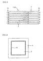
- Fig. 1 is a front view schematically showing an embodiment of the honeycomb structure and the honeycomb catalyst structure both of the present invention
- Fig. 2 is a sectional view schematically showing an embodiment of the honeycomb structure and the honeycomb catalyst structure both of the present invention
- the honeycomb structure 1 of the present embodiment has porous partition walls 4 having a large number of pores and plugged portions 10.
- the partition walls 4 are formed so as to produce a plurality of cells 3 extending between the two ends 2a and 2b of the honeycomb structure 1.
- the plugged portions 10 are produced so as to plug the cells 3 at either one end 2a or 2b of the honeycomb structure 1.
- a symbol 20 is an outer wall; a symbol P is a cell pitch; a symbol D is a cell hydraulic diameter; and a symbol T is a partition wall thickness.
- Each partition wall 4 of the honeycomb structure 1 of the present embodiment has a permeability of 7x10 -12 to 4x10 -8 m 2 , preferably 1x10 -11 to 8x10 -10 m 2 , more preferably 3x10 -11 to 3x10 -10 m 2 .
- each partition wall 4 has a permeability controlled in the above range and when such a honeycomb structure 1 has a particular catalyst carried thereon to use as a honeycomb catalyst structure 50, the fine carbon particles, etc. contained in an exhaust gas emitted from a diesel engine are hardly captured by the partition wall 4 and most of them pass through the partition wall 4. That is, as shown in Fig.
- each partition wall 4 of the honeycomb structure 1 of the present embodiment has a permeability controlled in a particular range, the fine carbon particles, etc. contained in the exhaust gas are hardly captured by each partition wall 4 of the honeycomb catalyst structure 50 obtained using the honeycomb structure 1.
- the honeycomb structure 1 of the present embodiment there can be obtained a honeycomb catalyst structure 50 which is low in pressure loss and, even when used over a long period, hardly shows any increase in pressure loss.
- honeycomb structure 1 of the present embodiment unlike in the case of a conventional honeycomb catalyst structure 60 such as shown in Figs. 4 to 6 , a catalyst layer 5 can be carried on the surface of each pore 25 of each partition wall 4, as shown in Fig. 3 . Therefore, there can be provided a compact honeycomb catalyst structure 50 which is superior in purification efficiency to the conventional honeycomb catalyst structure and can be mounted even in a limited space. Incidentally, the detailed description on the honeycomb structure 50 is made later.
- the "permeability" referred to in the present specification is a physical property calculated by the following expression (1) and is an index indicating the passing-through resistance shown when a target gas passes through a sample (partition wall).
- C is a permeability (m 2 ); F is a gas flow rate (cm 3 /s); T is a sample thickness (cm); V is a gas viscosity (dynes ⁇ sec/cm 2 ); D is a sample diameter (cm); and P is a gas pressure (PSI).
- PSI gas pressure
- Fig. 10 is a schematic view explaining a test piece used in the measurement of permeability.
- a test piece 100 is cut out from a honeycomb structure or a honeycomb catalyst structure in a state that a part (residual rib 105) of each partition wall intersecting one partition wall 4 is left at a residual rib height (H) of 0.2 mm.
- the shape of this test piece 100 may be a polygonal plate or a circular plate. Air of room temperature is passed through the test piece 100 and its permeability is calculated using the above-mentioned expression (1).
- a fluid seal such as grease or the like is used in combination with a sealing material so that no air is leaked from the gap between the test piece 100 and the sealing material, formed by the residual ribs 105.
- the flow rate of air is adjusted so that the calculated velocity of air during passing through partition wall becomes 0.1 to 1 cm/sec, and there is used a result measured with this air flow rate.
- the target of measuring the permeability is the partition walls of honeycomb catalyst structure
- the carried form of catalyst layer differs at the inner wall of cell and at the cut surface.
- a catalyst layer is carried on the inner surface of pores. Therefore, the effect of residual rib is small and the permeability of partition wall of honeycomb catalyst structure can be measured in the same manner as in the case of honeycomb structure.
- each plugged portion 10 is shown in a state that it is formed so as to plug a cell 3 at one end 2a or 2b.
- the formation state of plugged portion is not restricted to such a formation state.
- one plugged portion 10 can be formed inside each cell 3, as in the honeycomb structure 21 shown in Fig. 7 .
- the honeycomb structure 31 shown in Fig. 8 it is possible to form each one plugged portion 10 for part of the cells 3 and form no plugged portion 10 for the remaining cells 3.
- each one plugged portion 10 inside part of the cells 3 and form each one plugged portion 10 for the remaining cells 3 at their ends 2b. It is preferred that, as shown in Fig. 2 , a plugged portion 10 is formed for each cell at either one end 2a or 2b of honeycomb structure because a honeycomb catalyst structure superior in purification efficiency can be provided. As in the honeycomb structures shown in Figs. 7 to 9 , formation of plugged portion 10 inside cell 3 is preferred because a reduced pressure loss is obtained. Presence of cells 3 having no plugged portion 10, i.e. through-holes cells 3a, as shown in Fig. 8 is also preferred because a reduced pressure loss can be obtained.
- honeycomb structure 51 shown in Fig. 11
- honeycomb structure 61 shown in Fig. 12
- honeycomb structure 71 shown in Fig. 12
- a structure such as honeycomb structure 81 shown in Fig. 14 , wherein part of the cells 3 are through-hole cells 3a and the remaining cells 3 have each a plugged portion 10 at one end 2b (a gas outlet end).
- honeycomb structure 91 such as shown in Fig. 15 , wherein part of the cells 3 are through-hole cells 3a, the remaining cells 3 have each inside a plugged portion 10 at a different position in the central axis direction of the structure, and each through-hole cell 3a is divided by a thin partition wall 4a.
- the proportion of the through-hole cells having no plugged portion, in the total cells is preferably 30 to 90%, more preferably 30 to 50%. When the proportion is less than 30%, the effect of reduced pressure loss may not be obtained sufficiently; when the proportion is more than 90%, no sufficient purification efficiency may be obtained.
- the pressure loss arising when a gas passes through cells is in inverse proportion to the square of cell hydraulic diameter. Also, the ratio of the pressure loss arising when a gas passes through each partition wall (the pressure loss during passing through partition wall) and the pressure loss during passing through cell; "(pressure loss during passing through partition wall)/(pressure loss during passing through cell)” is in proportion to "(cell hydraulic diameter) 2 /(permeability)".
- a "(cell hydraulic diameter) 2 /(permeability)" of 2 x 10 3 or more is preferred because, when such a honeycomb structure 1 is made into a honeycomb catalyst structure 50, a gas can easily pass uniformly through the whole portions of the partition walls 4 of the honeycomb catalyst structure 50.
- a "(cell hydraulic diameter) 2 /(permeability)" of less than 6x10 5 is preferred because, when such a honeycomb structure 1 is made into a honeycomb catalyst structure 50, there is substantially no increase in pressure loss in the whole portion of the structure 50.
- the density of cells 3 (cell density) of the honeycomb structure 1 of the present embodiment is preferably 0.25 to 46.5 cells/cm 2 (1.61-300 cpsi), more preferably 1.55 to 15.5 cells/cm 2 (10 to 100 cpsi), particularly preferably 1.55 to 12.4 cells/cm 2 (10 to 80 cpsi).
- cpsi is an abbreviation of "cells per square inch” and is a unit indicating the number of cells per square inch. 10 cpsi is about 1.55 cells/cm 2 .
- partition wall thickness T is preferably 0.15 to 7 mm (5.9 to 276 mil), more preferably 0.4 to 2 mm (15.7 to 78.7 mil), particularly preferably 0.7 to 1.5 mm (27.6 to 59 mil).
- partition wall thickness T is less than 0.15 mm, the strength is insufficient and the thermal shock resistance may be low. Meanwhile, when the partition wall thickness T is more than 7 mm, the pressure loss tends to be large.
- 1 mil is 1/1,000 inch and is about 0.025 mm.
- the image maximum distance average of partition wall 4 is preferably 40 to 3,000 ⁇ m, more preferably 50 to 500 ⁇ m, particularly preferably larger than 250 ⁇ m but not larger than 500 ⁇ m.
- the image maximum distance average is smaller than 40 ⁇ m, an increase in pressure loss tends to arise since fine particles such as fine carbon particles contained in the exhaust gas emitted from a diesel engine are captured easily.
- the image maximum distance average is larger than 3,000 ⁇ m, it tends to become difficult to secure the sufficient contact area between exhaust gas and catalyst layer.
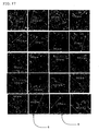
- "pore diameter" referred to in the present specification is a physical property value measured by image analysis.
- each maximum straight line distance is, from the uppermost column left end toward right end and from upper column toward lower column, 387 ⁇ m, 442 ⁇ m, 327 ⁇ m, 179 ⁇ m, 275 ⁇ m, 255 ⁇ m, 303 ⁇ m, 377 ⁇ m, 350 ⁇ m, 185 ⁇ m, 353 ⁇ m, 153 ⁇ m, 332 ⁇ m, 245 ⁇ m, 257 ⁇ m, 302 ⁇ m, 207 ⁇ m, 465 ⁇ m, 320 ⁇ m and 301 ⁇ m. In this case, the image maximum distance average becomes 301 ⁇ m.
- magnification of SEM photograph may be any magnification as long as a clear image is obtained and, for example, any magnification ranging from 10 to 1,000 can be selected.
- the porosity of partition wall 4 is preferably 30 to 80%, more preferably 40 to 65%, particularly preferably 50 to 65%.
- porosity is less than 30%, the velocity of gas during passing through partition wall increases and the purification efficiency for gas tends to be deteriorated. Meanwhile, when the porosity is more than 80%, the strength of partition wall tends to be insufficient.
- porosity referred to in the present specification is a physical property value measured by image analysis.
- the combination of the density of cell, the thickness of partition wall, the image maximum distance average of partition wall, and the porosity of partition wall there are preferred a cell density of 4 to 46.5 cells/cm 2 , a partition wall thickness of 0.3 to 0.43 mm, an image maximum distance average of partition wall, of larger than 250 ⁇ m but not larger than 500 ⁇ m, and a partition wall porosity of 40 to 65%.
- the resulting honeycomb structure can be suitably used as a carrier for constituting a catalyst structure for industrially purifying the exhaust gas emitted from industrial combustion equipment.
- the standard deviation of the common logarithm of pore diameter distribution of partition wall 4, i.e. pore diameter distribution ⁇ is preferably 0.1 to 0.6, more preferably 0.2 to 0.6.
- pore diameter distribution ⁇ is less than 0.1, the pressure loss during passing through partition wall tends to increase.
- partition wall distribution ⁇ is more than 0.6, a gas passes through only large pores and resultantly the purification performance for gas tends to deteriorate.
- the "pore diameter distribution" used for determination of "standard deviation of the common logarithm of pore diameter distribution” is measured using a mercury porosimeter and, using the pore diameter distribution obtained and the following expressions (2) to (5), there is determined a standard deviation of common logarithm [sd (standard deviation) in the following expression (5)].
- a standard deviation of common logarithm [sd (standard deviation) in the following expression (5)].
- the differential pore volume f2 is a value indicated by (V2 - V1).
- Dp indicates pore diameter ( ⁇ m);
- f indicates differential pore volume (mL/g);
- x indicates the common logarithm of pore diameter Dp;
- xav indicates an average of x;
- s 2 indicates a variance of x;
- sd indicates the standard deviation (standard deviation of the common logarithm of pore diameter distribution) of x.
- such a honeycomb structure is suitable as a carrier for constituting an industrial catalyst structure for purifying the exhaust gas emitted from industrial combustion equipment.
- the partition wall thickness is 0.7 to 1.5 mm
- the image maximum distance average of partition wall is larger than 250 ⁇ m but not larger than 500 ⁇ m
- the porosity of partition wall is 40 to 65%
- the standard deviation of the common logarithm of pore diameter distribution of partition wall is 0.2 to 0.6
- the material constituting the honeycomb structure 1 of the present embodiment there can be mentioned a material contained a ceramic as a major component and a sintered metal.
- a material contained a ceramic as a major component there can be mentioned silicon carbide, cordierite, alumina titanate, sialon, mullite, silicon nitride, zirconium phosphate, zirconia, titania, alumina, silica and combinations thereof.
- ceramics such as silicon carbide, cordierite, mullite, silicon nitride, alumina and the like, for the alkali resistance. Of these, oxide type ceramics are preferred from the cost standpoint.
- the thermal expansion coefficient of the honeycomb structure 1 of the present embodiment, at 40 to 800°C in the cell-extending direction is preferably less than 1.0x10 -6 /°C, more preferably less than 0.8x10 -6 /°C, particularly preferably 0.5x10 -6 /°C.
- the thermal expansion coefficient in the cell-extending direction at 40 to 800°C is less than 1.0x10 -6 /°C, the thermal stress generating when exposed to an exhaust gas of high temperature, can be suppressed in an allowable range and the thermal stress-destruction of the honeycomb structure can be prevented.
- the sectional shape obtained when the honeycomb structure 1 of the present embodiment has been cut in the radial direction at a plane perpendicular to the cell-extending direction is preferred to be a shape suited to the internal shape of an exhaust gas system to which the honeycomb structure 1 is to be fitted.
- specific sectional shapes there can be mentioned a circle, an ellipse, an oblong circle, a trapezoid, a triangle, a tetragon, a hexagon and a special shape which is asymmetric in the right and the left. Of these, a circle, an ellipse and an oblong circle are preferred.
- the honeycomb structure of the present invention can be produced based on, for example, a known conventional process for producing a diesel particulate filter (DPF).
- DPF diesel particulate filter
- the permeability of the partition wall is controlled in a particular range; therefore, the permeability of the partition wall is controlled in a particular range, for example, by appropriately selecting and preparing the chemical composition of the materials used, or, when a pore former is used for obtaining a porous structure, appropriately selecting and preparing the kind, particle size, addition amount, etc. of the pore former used.
- the honeycomb catalyst structure 50 of the present embodiment has a honeycomb structure 1 and a catalyst layer 5 containing a catalyst.
- the catalyst layer 5 is carried in a layered form on the inner surfaces of pores 25, and a large number of catalyst-carried pores 35 are formed inside each partition wall 4.
- adjacent cells 3 communicate with each other via each catalyst-carried pore 35.
- a catalyst layer 15 may be formed on the inner surface of each cell 3.
- the partition walls 4 of the honeycomb structure 1 has a permeability specified in a particular range, as mentioned previously. Therefore, in the honeycomb catalyst structure 50 of the present embodiment wherein a catalyst layer 5 is carried on the inner surface of each pore 25 of the honeycomb structure 1, the fine carbon particles, etc. contained in an exhaust gas emitted from a diesel engine are hardly captured by the partition walls 4 and most of them pass through the partition walls 4. That is, as shown in Fig. 2 , the exhaust gas which has flowed into each cell 3 of the honeycomb catalyst structure 50 from its one end 2a, passes through each partition wall 4, migrates into adjacent cells 3, and then is discharged outside from other end 2b. Therefore, the honeycomb catalyst structure 50 of the present embodiment is low in pressure loss and, even when used over a long period, hardly shows any increase in pressure loss.
- the honeycomb catalyst structure 50 of the present embodiment unlike in the case of a conventional honeycomb catalyst structure 60 such as shown in Figs. 4 to 6 , a catalyst layer 5 is carried on the surface of each pore 25 of each partition wall 4. Therefore, the honeycomb catalyst structure 50 is a compact catalyst structure which is superior in purification efficiency to the conventional honeycomb catalyst structure and which can be mounted even.in a limited space.
- Preferred embodiments of the honeycomb catalyst structure of the present invention include also honeycomb catalyst structures 70, 80 and 90 obtained by forming a catalyst layer on the surface of each pore of each partition wall 4 of the honeycomb structure 21, 31 or 41 shown in Fig. 7, 8 or 9 .
- Preferred embodiments of the honeycomb catalyst structure of the present invention include also honeycomb catalyst structures 110, 120, 130, 140 and 150 obtained by forming a catalyst layer on the surface of pores of partition walls 4 of the honeycomb structure 51, 61, 71, 81 or 91 shown in Fig. 11, 12 , 13, 14 or 15 .
- Each partition wall 4 of the honeycomb catalyst structure 50 of the present embodiment has a permeability of preferably 6.8x10 -12 to 3x10 -8 m 2 , more preferably 8x10 -12 to 6x10 -10 m 2 , particularly preferably 2x10 -11 to 2x10 -10 m 2 .
- the permeability of the partition wall 4 is less than 6.8x10 -12 m 2 , the pressure loss is large and, in long-term use, the pressure loss tends to increase. Meanwhile, when the permeability of the partition wall 4 is more than 3x10 -8 m 2 , it tends to become difficult to secure the sufficient contact area between exhaust gas and catalyst layer 5.
- a (cell hydraulic diameter) 2 /(permeability) of 2x10 3 or more is preferred because a gas flows easily and uniformly in the entire portions of partition walls 4. Meanwhile, a (cell hydraulic diameter) 2 /(permeability) of less than 6x10 5 is preferred because the pressure loss of the whole honeycomb catalyst structure 50 increases hardly.
- the image maximum distance average of partition wall 4 in a state that a catalyst layer 5 has been carried on the partition wall 4, that is, in a state that catalyst-carried pores 3 have been formed is preferably 40 to 3,000 ⁇ m, more preferably 50 to 500 ⁇ m, particularly preferably larger than 250 ⁇ m but not larger than 500 ⁇ m.
- the image maximum distance average is smaller than 40 ⁇ m, fine particles such as fine carbon particles contained in the exhaust gas emitted from a diesel engine are captured easily and an increase in pressure loss tends to arise. Meanwhile, when the image maximum distance average is larger than 3,000 ⁇ m, it tends to become difficult to secure the sufficient contact area between exhaust gas and catalyst layer.
- the porosity of partition wall 4 in a state that a catalyst layer 5 has been carried on the partition wall 4, that is, in a state that catalyst-carried pores 3 have been formed is preferably 30 to 80%, more preferably 40 to 65%, particularly preferably 50 to 65%.
- the porosity is less than 30%, the velocity of gas during passing through partition wall increases and the purification efficiency for gas tends to deteriorate. Meanwhile, when the porosity is more than 80%, the strength of partition wall tends to be insufficient.
- the resulting honeycomb catalyst structure is suitable as an industrial catalyst structure for purifying the exhaust gas emitted from industrial combustion equipment.
- the image maximum distance average is larger than 250 ⁇ m but not larger than 500 ⁇ m and the porosity is 40 to 65%
- the resulting honeycomb catalyst structure is suitable as an industrial catalyst structure, particularly a catalyst structure for vehicle mounting, for purification of the exhaust gas emitted from automobile engines.
- the ratio (L/d) of the equivalent diameter d of honeycomb catalyst structure and the length L of honeycomb catalyst structure in central axis direction is preferably more than 0.3 but less than 0.75, more preferably 0.3 to 0.5.
- the "equivalent diameter d" is a value obtained by quadruplicating the area of the section of honeycomb catalyst structure perpendicular to central axis and dividing the product by the "length of circumference of the section".
- the ratio (L/d) of the equivalent diameter d and the length L in central axis direction is 0.3 or more but less than 0.75
- the cell density is 4 to 46.5 cells/cm 2
- the partition wall thickness is 0.3 to 0.43 mm
- the image maximum distance average is 250 to 500 ⁇ m
- the porosity is 60 to 80%
- the standard deviation of the common logarithm of pore diameter distribution is 0.2 to 0.6.
- the catalyst contained in the catalyst layer 5 constituting the honeycomb catalyst structure 50 of the present embodiment there can be mentioned (1) a three-way catalyst for purification of exhaust gas of gasoline engine, (2) an oxidation catalyst for purification of exhaust gas of gasoline engine or diesel engine, (3) a SCR catalyst for NOx selective reduction, and (4) an NOx storage catalyst.
- the three-way catalyst for purification of exhaust gas of gasoline engine contains a carrier coat for covering of partition walls of honeycomb structure (honeycomb carrier) and a noble metal dispersed in and carried on the carrier coat.
- the carrier coat is constituted by, for example, active alumina.
- the noble metal dispersed in and carried on the carrier coat there can be mentioned Pt, Rh, Pd and combinations thereof.
- the carrier coat further contains a compound such as cerium oxide, zirconium oxide, silica or the like, or a mixture thereof. Incidentally, it is preferred that the total amount of noble metals is controlled at 0.17 to 7.07 g per liter of honeycomb structure.
- the oxidation catalyst for purification of exhaust gas of gasoline engine or diesel engine contains a noble metal.
- the noble metal there is preferred at least one member selected from the group consisting of Pt, Rh and Pd. Incidentally, it is preferred that the total amount of noble metals is controlled at 0.17 to 7.07 g per liter of honeycomb structure.
- the SCR catalyst for NOx selective reduction contains at least one member selected from the group consisting of metal-substituted zeolite, vanadium, titania, tungsten oxide, silver and alumina.
- the NOx storage catalyst contains an alkali metal and/or an alkaline earth metal.
- the alkali metal there can be mentioned K, Na and Li.
- the alkaline earth metal Ca can be mentioned. Incidentally, it is preferred that the total amount of K, Na, Li and Ca is controlled at 5 g or more per liter of honeycomb structure.
- the honeycomb catalyst structure of the present invention can be produced by carrying a catalyst on the above-mentioned honeycomb structure based the known conventional method. Specifically explaining, firstly, a catalyst slurry containing a catalyst is prepared; then, the catalyst slurry is coated on the pore surfaces of the partition walls of a honeycomb structure by suction or the like; thereafter, drying is conducted at room temperature or with heating; thereby, a honeycomb catalyst structure of the present invention can be produced.
- C is a permeability (m 2 ); F is a gas flow rate (cm 3 /s); T is a sample thickness (cm); V is a gas viscosity (dynes ⁇ sec/cm 2 ); D is a sample diameter (cm); and P is a gas pressure (PSI).
- PSI gas pressure
- 13.839 (PSI) 1 (atm)
- 68947.6 (dynes ⁇ sec/cm 2 ) 1 (PSI).
- an apparatus such as Capillary Flow Pormeter Model 1100AEX (trade name) produced by Porous Materials, Inc.
- Purification index A combustion gas consisting of 7 vol. % of oxygen, 10 vol. % of steam, 10 vol. % of carbon dioxide, 200 ppm (in terms of carbon moles) of hydrocarbons and the remainder of nitrogen was allowed to flow into a honeycomb structure or a honeycomb catalyst structure at a space velocity (SV) of 100,000 h -1 at 200°C. Hydrocarbons concentrations in combustion gas before and after flowing-into were measured and a purification ratio (%) was calculated. Also, a purification ratio (a standard purification ratio) (%) was calculated for a honeycomb catalyst structure for comparison, and the proportion of the above purification ratio to the standard purification ratio was calculated and taken as purification index (%).
- SV space velocity
- the honeycomb catalyst structure for comparison one shown in Figs. 4 to 6 , obtained by carrying a catalyst on a simple honeycomb structure (without plugged portion) having a cell density of 600 cpsi (93 cells/cm 2 ) and a partition wall thickness of 4.5 mil (0.1143 mm).
- the honeycomb catalyst structure for comparison one shown in Figs. 4 to 6 , obtained by carrying a catalyst on a simple honeycomb structure (without plugged portion) having a cell density of 30 cpsi (4.65 cells/cm 2 ) and a partition wall thickness of 32 mil (0.8128 mm).
- a pressure loss (a standard pressure loss) was also measured for a honeycomb catalyst structure for comparison, of the same shape, the same cell density and the same partition wall thickness.
- a plurality of members selected from talc, kaolin, calcinated kaolin, alumina, aluminum hydroxide and silica were mixed as raw materials for formation of cordierite, in such proportions as to give a chemical composition of 42 to 56 mass % of SiO 2 , 0 to 45 mass % of Al 2 O 3 and 12 to 16 mass % of MgO.
- To 100 parts by mass of the resulting mixture were added 12 to 25 parts by mass of graphite as a pore former and 5 to 15 parts by mass of a synthetic resin.
- honeycomb formed material was degassed under vacuum and then subjected to extrusion molding to obtain a honeycomb formed material.
- the honeycomb formed material was dried and then fired at the maximum temperature of 1,400 to 1,430°C to obtain a honeycomb fired material.
- a plugging material was filled at either one end of the honeycomb fired material, followed by refiring, whereby were produced honeycomb structures (Examples 1 to 17 and Comparative Examples 1 to 3) of 144 mm in diameter and 152 mm in total length, having a partition wall pore structure shown in Table 1.
- the partition wall pore structure was adjusted by appropriately adjusting the chemical composition of raw materials for formation of cordierite, the particle diameter of pore former, the addition amount of pore former, etc.
- the plugging depth (length) of each plugged portion was 10 mm from the end.
- a catalyst slurry containing platinum (Pt) as a noble metal and further containing active alumina and, as an oxygen-storage agent, ceria was prepared.
- the catalyst slurry was coated, by suction, on the inner surface of partition wall and inner surface of pore of each of the honeycomb structures of Examples 1 to 17 and Comparative Examples 1 to 3, to prepare a coated layer of the catalyst slurry.
- drying was conducted with heating to produce honeycomb catalyst structures of Examples 18 to 34 and Comparative Examples 4 to 6, each having a pore structure of partition wall (with catalyst layer) shown in Table 2.
- the amount of noble metal (Pt) per liter of honeycomb structure (carrier) was 2 g.
- the coated amount of catalyst slurry per liter of honeycomb structure (carrier) was 100 g.
- honeycomb catalyst structures of Examples 18 to 34 and Comparative Examples 4 to 6 were measured and calculated for purification index and pressure loss increase ratio. The results are shown in Table 3. These structures were also evaluated for pressure loss increase and long-term plugging resistance. The results are shown in Table 3.
- honeycomb catalyst structures of Examples 18 to 34 produced using the honeycomb structures of Examples 1 to 17, as compared with the honeycomb catalyst structures of Comparative Examples 4 to 6, are high in purification index and show superior purification performances. It is also clear that the honeycomb catalyst structures of Examples 18 to 34, as compared with the honeycomb catalyst structures of Comparative Examples 4 to 6, show no pressure loss increase, are low in pressure loss increase ratio, and good in long-term plugging resistance.
- a honeycomb fired material was produced in the same manner as in Example 1. Part of the cells of the honeycomb fired material were left as through-hole cells; the remaining cells were filled with a plugging material at each one end (gas inlet side end); and the resulting honeycomb material was fired again to obtain four kinds of honeycomb structures which were similar in structure to the honeycomb structure 71 shown in Fig. 13 and wherein the proportions of through-hole cells were different from each other.
- the proportions (%) of through-hole cells were 35% (Example 35), 45% (Example (36), 55% (Example 37) and 20% (Example 38).
- Each honeycomb structure obtained was a cordierite-made honeycomb structure having a diameter of 105.7 mm, a length of 114.2 mm (resultantly, a volume of 1 liter), a partition wall thickness of 8 mil (0.203 mm), a cell density of 300 cells/in 2 (46.5 cells/cm 2 ), an image maximum distance average of partition wall, of 40 ⁇ m, and a partition wall porosity of 60%.
- a catalyst slurry was sucked under vacuum from the outlet side end of each honeycomb structure obtained above, to carry, on the surface of each partition wall, 150 of ⁇ -alumina/ceria, 2 g of platinum (Pt) and 0.5 g of rhodium (Rh) per liter of honeycomb structure to obtain honeycomb catalyst structures of Examples 35 to 38.
- the catalyst slurry was prepared according to the methods mentioned below.
- Each honeycomb catalyst structure was measured for purification ratio of hydrocarbons and pressure loss according to the following methods. The results obtained are shown in Table 4 (plugged pattern 1).
- a ⁇ -alumina/ceria mixture (specific surface are: 50 m 2 /g, initial, disintegrated particle diameter: 50 ⁇ m) was wet-disintegrated in a ball mill to convert the diameter into an average, disintegrated particle diameter of 5 ⁇ m.
- the resulting disintegrated particles were mixed with a solution containing platinum and rhodium to carry platinum and rhodium in the fine pores of ⁇ -alumina. Thereby was obtained a catalyst slurry containing ⁇ -alumina of 5 ⁇ m in average, disintegrated particle diameter, carried with platinum and rhodium.
- the unit has no dimension.
- the unit has no dimension.
- honeycomb structures Four kinds of honeycomb structures were obtained in the same manner as in Example 35 except that the positions for filling a plugging material (the positions for formation of plugged portions) and the proportions of through-hole cells were changed.
- the honeycomb structures obtained as in the honeycomb structure 81 shown in Fig. 14 , part of the cells 3 were through-hole cells 3a and the remaining cells 3 had each a plugged portion 10 at one end 2b (a gas outlet side end).
- the proportions of through-hole cells were 35% (Example 39), 45% (Example 40), 55% (Example 41) and 20% (Example 42).
- honeycomb structure obtained was carried with a catalyst in the same manner as in Example 35, to obtain honeycomb catalyst structures of Examples 39 to 42.
- honeycomb catalyst structure was measured for hydrocarbon purification ratio and pressure loss according to the above-mentioned methods. The results obtained are shown in Table 4 (plugged pattern 2).
- honeycomb structures Four kinds of honeycomb structures were obtained in the same manner as in Example 35 except that the positions for filling a plugging material (the positions for formation of plugged portions) and the proportions of through-hole cells were changed.
- the honeycomb structures obtained as in the honeycomb structure 51 shown in Fig. 11 , part of the cells 3 were through-hole cells 3a and the remaining cells 3 had each a plugged portion 10 at end 2a or end 2b.
- the proportions of through-hole cells were 35% (Example 43), 45% (Example 44), 55% (Example 45) and 20% (Example 46).
- honeycomb structure obtained was carried with a catalyst in the same manner as in Example 35, to obtain honeycomb catalyst structures of Examples 43 to 46.
- honeycomb catalyst structure was measured for hydrocarbon purification ratio and pressure loss according to the above-mentioned methods. The results obtained are shown in Table 4 (plugged pattern 3).
- honeycomb structures Four kinds of honeycomb structures were obtained in the same manner as in Example 35 except that the positions for filling a plugging material (the positions for formation of plugged portions) and the proportions of through-hole cells were changed.
- the honeycomb structures obtained as in the honeycomb structure 61 shown in Fig. 12 , part of the cells 3 were through-hole cells 3a and the remaining cells 3 had each inside a plugged portion 10 so that such plugged portions 10 were arranged at the same position in the central axis direction of the honeycomb structure.
- the proportions of through-hole cells were 35% (Example 47), 45% (Example 48), 55% (Example 49) and 20% (Example 50).
- honeycomb structure obtained was carried with a catalyst in the same manner as in Example 35, to obtain honeycomb catalyst structures of Examples 47 to 50.
- honeycomb catalyst structure was measured for hydrocarbon purification ratio and pressure loss according to the above-mentioned methods. The results obtained are shown in Table 4 (plugged pattern 4).
- honeycomb structures Four kinds of honeycomb structures were obtained in the same manner as in Example 35 except that the positions for filling a plugging material (the positions for formation of plugged portions) and the proportions of through-hole cells were changed.
- the honeycomb structures obtained as in the honeycomb structure 31 shown in Fig. 8 , part of the cells 3 were through-hole cells 3a and the remaining cells 3 had each inside a plugged portion 10 at a different position in the central axis direction of the honeycomb structure.
- the proportions of through-hole cells were 35% (Example 51), 45% (Example 52), 55% (Example 53) and 20% (Example 54).
- honeycomb structure obtained was carried with a catalyst in the same manner as in Example 35, to obtain honeycomb catalyst structures of Examples 51 to 55.
- honeycomb catalyst structure was measured for hydrocarbon purification ratio and pressure loss according to the above-mentioned methods. The results obtained are shown in Table 4 (plugged pattern 5).
- a honeycomb structure was obtained in the same manner as in Example 35 except that the positions for filling a plugging material (the positions for formation of plugged portions) and the proportion of through-hole cells were changed.
- the honeycomb structure obtained as in the honeycomb structure 1 shown in Fig. 2 , there was no through-hole cell and all the cells 3 had each a plugged portion 10 at end 2a or end 2b so that each end showed a checkered pattern.
- honeycomb structure obtained was carried with a catalyst in the same manner as in Example 35, to obtain a honeycomb catalyst structure of Example 55.
- honeycomb catalyst structure was measured for hydrocarbon purification ratio and pressure loss according to the above-mentioned methods. The results obtained are shown in Table 4 (plugged pattern 6).
- Honeycomb catalyst structures of Examples 56 to 61, each having a pore structure of partition wall (with catalyst layer) shown in Table 2 were produced in the same manner as used in production of the honeycomb catalyst structure of Example 18.
- honeycomb catalyst structures of Examples 56 to 61 were measured and calculated for purification index and pressure loss increase ratio. The results are sown in Table 6. They were also evaluated for long-term plugging resistance. The results are shown in Table 6.
- Honeycomb catalyst structures of Examples 61 and 62 and Comparative Examples 7 and 8 each having a pore structure of partition wall (with catalyst layer) shown in Table 7 were produced in the same manner as used in production of the honeycomb catalyst structure of Example 18.
- honeycomb catalyst structure of the present invention is superior in purification efficiency, is small in pressure loss and can be mounted even in a limited space. Therefore, the honeycomb catalyst structure of the present invention can be suitably used in purification of to-be-purified components contained in, for example, the exhaust gases emitted from automobile engines, construction equipment engines, industrial stationary engines, combustion equipment, etc.
Landscapes
- Chemical & Material Sciences (AREA)
- Engineering & Computer Science (AREA)
- Ceramic Engineering (AREA)
- Chemical Kinetics & Catalysis (AREA)
- Physics & Mathematics (AREA)
- Geometry (AREA)
- Materials Engineering (AREA)
- Organic Chemistry (AREA)
- Structural Engineering (AREA)
- Manufacturing & Machinery (AREA)
- Life Sciences & Earth Sciences (AREA)
- Geology (AREA)
- Inorganic Chemistry (AREA)
- Thermal Sciences (AREA)
- Health & Medical Sciences (AREA)
- Toxicology (AREA)
- Combustion & Propulsion (AREA)
- Mechanical Engineering (AREA)
- General Engineering & Computer Science (AREA)
- Catalysts (AREA)
- Exhaust Gas Treatment By Means Of Catalyst (AREA)
- Exhaust Gas After Treatment (AREA)
Applications Claiming Priority (3)
| Application Number | Priority Date | Filing Date | Title |
|---|---|---|---|
| JP2005250872 | 2005-08-31 | ||
| JP2006055781 | 2006-03-02 | ||
| PCT/JP2006/317184 WO2007026803A1 (fr) | 2005-08-31 | 2006-08-31 | Structure en nid d’abeille et substance catalytique en nid d’abeille |
Publications (2)
| Publication Number | Publication Date |
|---|---|
| EP1920838A1 true EP1920838A1 (fr) | 2008-05-14 |
| EP1920838A4 EP1920838A4 (fr) | 2012-01-25 |
Family
ID=37804552
Family Applications (1)
| Application Number | Title | Priority Date | Filing Date |
|---|---|---|---|
| EP06797144A Ceased EP1920838A4 (fr) | 2005-08-31 | 2006-08-31 | Structure en nid d abeille et substance catalytique en nid d abeille |
Country Status (4)
| Country | Link |
|---|---|
| US (1) | US7867598B2 (fr) |
| EP (1) | EP1920838A4 (fr) |
| JP (1) | JPWO2007026803A1 (fr) |
| WO (1) | WO2007026803A1 (fr) |
Cited By (5)
| Publication number | Priority date | Publication date | Assignee | Title |
|---|---|---|---|---|
| EP2058042A4 (fr) * | 2006-08-30 | 2012-05-09 | Hitachi Metals Ltd | Filtre céramique en nid d'abeilles |
| EP1997556A4 (fr) * | 2006-03-13 | 2012-12-19 | Ngk Insulators Ltd | Structure de catalyseur en nid d'abeille |
| US8414838B2 (en) | 2009-12-01 | 2013-04-09 | Ibiden Co., Ltd. | Honeycomb filter and exhaust gas purifying apparatus |
| US8617476B2 (en) | 2009-10-09 | 2013-12-31 | Ibiden Co., Ltd. | Honeycomb filter and urea SCR device |
| CN104813000A (zh) * | 2012-11-30 | 2015-07-29 | 陶氏环球技术有限责任公司 | 用蜂窝式过滤器过滤汽油直接喷射发动机废料 |
Families Citing this family (56)
| Publication number | Priority date | Publication date | Assignee | Title |
|---|---|---|---|---|
| WO2009100097A2 (fr) | 2008-02-05 | 2009-08-13 | Basf Catalysts Llc | Systèmes de traitement des émissions de moteur à essence comportant des pièges à particules |
| JP5073303B2 (ja) * | 2006-03-24 | 2012-11-14 | 日本碍子株式会社 | 触媒コンバータ及び触媒コンバータの製造方法 |
| JP2007289926A (ja) * | 2006-03-31 | 2007-11-08 | Ngk Insulators Ltd | ハニカム構造体及びハニカム触媒体 |
| US9272271B2 (en) | 2007-09-19 | 2016-03-01 | General Electric Company | Manufacture of catalyst compositions and systems |
| US9375710B2 (en) | 2007-09-19 | 2016-06-28 | General Electric Company | Catalyst and method of manufacture |
| JP5402638B2 (ja) * | 2007-10-12 | 2014-01-29 | 日立金属株式会社 | コージェライト質セラミックハニカムフィルタ及びその製造方法 |
| JP5368776B2 (ja) * | 2007-12-03 | 2013-12-18 | 日本碍子株式会社 | ハニカム構造体 |
| US8361592B2 (en) | 2007-12-03 | 2013-01-29 | Ngk Insulators, Ltd. | Honeycomb structure, honeycomb catalytic body and manufacturing method of the same |
| JP2009154124A (ja) * | 2007-12-27 | 2009-07-16 | Ngk Insulators Ltd | 部分目封止レスdpf |
| WO2009101683A1 (fr) * | 2008-02-13 | 2009-08-20 | Ibiden Co., Ltd. | Processus de production d'une structure en nid d'abeilles |
| JP5328174B2 (ja) * | 2008-02-20 | 2013-10-30 | 日本碍子株式会社 | 目封止ハニカム構造体 |
| JP5249791B2 (ja) * | 2008-03-27 | 2013-07-31 | イビデン株式会社 | ハニカム構造体 |
| JPWO2009122534A1 (ja) | 2008-03-31 | 2011-07-28 | イビデン株式会社 | ハニカム構造体 |
| DE102008019814A1 (de) * | 2008-04-19 | 2009-10-22 | Daimler Ag | Abgasreinigungskörper und Brennkraftmaschine mit Abgasreinigungskörper |
| JP5273446B2 (ja) * | 2008-05-12 | 2013-08-28 | 日産自動車株式会社 | 排ガス浄化用触媒及びその製造方法 |
| FR2931697B1 (fr) * | 2008-05-29 | 2011-04-29 | Saint Gobain Ct Recherches | Filtre ou support catalytique a base de carbure de silicium et de titanate d'aluminium |
| FR2931698B1 (fr) * | 2008-05-29 | 2011-01-07 | Saint Gobain Ct Recherches | Structure en nid d'abeille a base de titanate d'aluminium. |
| CN102046263A (zh) * | 2008-05-29 | 2011-05-04 | 康宁股份有限公司 | 部分壁流式过滤器和方法 |
| WO2009156652A1 (fr) * | 2008-05-29 | 2009-12-30 | Saint-Gobain Centre De Recherches Et D'etudes Europeen | Structure en nid d'abeille a base de titanate d'aluminium |
| BRPI0913881A2 (pt) * | 2008-06-27 | 2019-09-24 | Umicore Ag & Co Kg | processo para realizar reações catalizadas de forma heterogênea com alta seletividade e rendimento |
| JP2010167366A (ja) * | 2009-01-22 | 2010-08-05 | Ngk Insulators Ltd | ハニカム触媒体 |
| US20100196237A1 (en) | 2009-01-30 | 2010-08-05 | General Electric Company | Templated catalyst composition and associated method |
| US20100196236A1 (en) | 2009-01-30 | 2010-08-05 | General Electric Company | Templated catalyst composition and associated method |
| JP5419505B2 (ja) * | 2009-03-24 | 2014-02-19 | 日本碍子株式会社 | ハニカム構造体の製造方法及びハニカム触媒体の製造方法 |
| JP2011224538A (ja) * | 2009-12-01 | 2011-11-10 | Ibiden Co Ltd | ハニカムフィルタ及び排ガス浄化装置 |
| JP4920752B2 (ja) * | 2010-01-05 | 2012-04-18 | 日本碍子株式会社 | ハニカム構造体 |
| WO2011125766A1 (fr) * | 2010-03-31 | 2011-10-13 | 日本碍子株式会社 | Filtre en nid d'abeilles |
| CN102834158B (zh) * | 2010-04-01 | 2015-07-15 | 日立金属株式会社 | 陶瓷蜂窝过滤器及其制造方法 |
| US8815189B2 (en) | 2010-04-19 | 2014-08-26 | Basf Corporation | Gasoline engine emissions treatment systems having particulate filters |
| GB2484911B (en) * | 2010-10-22 | 2013-04-03 | Johnson Matthey Plc | NOx absorber catalyst comprising caesium silicate and at least one platinum group metal |
| JP5813965B2 (ja) * | 2011-03-03 | 2015-11-17 | 日本碍子株式会社 | ハニカム構造体及び排ガス浄化装置 |
| JP5486539B2 (ja) * | 2011-03-30 | 2014-05-07 | 日本碍子株式会社 | ハニカム構造体及びその製造方法 |
| US20120329644A1 (en) | 2011-06-21 | 2012-12-27 | General Electric Company | Catalyst composition and catalytic reduction system |
| US9346043B2 (en) * | 2012-03-06 | 2016-05-24 | Ngk Insulators, Ltd. | Honeycomb structure and honeycomb catalyst |
| JP6081831B2 (ja) | 2012-03-19 | 2017-02-15 | 日本碍子株式会社 | ハニカム構造体およびこれを用いたハニカム触媒体、ならびにハニカム構造体の製造方法 |
| US8978601B2 (en) | 2012-12-12 | 2015-03-17 | Caterpillar Inc. | Six-stroke engine system with blowdown exhaust system |
| US9151222B2 (en) | 2012-12-12 | 2015-10-06 | Caterpillar Inc. | Six-stroke combustion cycle engine and process |
| US9133764B2 (en) | 2012-12-12 | 2015-09-15 | Caterpillar Inc. | Six-stroke engine system with blowdown exhaust recirculation |
| US9057324B2 (en) | 2012-12-12 | 2015-06-16 | Caterpillar Inc. | Six-stroke engine system with blowdown turbocharger |
| US8978602B2 (en) | 2012-12-12 | 2015-03-17 | Caterpillar Inc. | Six-stroke engine power density matching system and method |
| US8978603B2 (en) | 2012-12-12 | 2015-03-17 | Caterpillar Inc. | Six-stroke internal combustion engine valve activation system and method for operating such engine |
| US9181830B2 (en) | 2012-12-12 | 2015-11-10 | Caterpillar Inc. | After-treatment system and method for six-stroke combustion cycle |
| US9757675B2 (en) * | 2013-01-29 | 2017-09-12 | Corning Incorporated | Partial wall-flow filter and method |
| US20140238242A1 (en) * | 2013-02-28 | 2014-08-28 | Corning Incorporated | Ceramic partial wall-flow filter with low deep bed |
| CN105008050B (zh) | 2013-04-02 | 2017-07-28 | 日立金属株式会社 | 陶瓷蜂窝结构体及其制造方法 |
| JP6502133B2 (ja) | 2014-03-28 | 2019-04-17 | 日本碍子株式会社 | 多孔質体、ハニカムフィルタ、多孔質体の製造方法、及びハニカムフィルタの製造方法 |
| JP6285247B2 (ja) * | 2014-03-31 | 2018-02-28 | 日本碍子株式会社 | ハニカム構造体 |
| JP6578938B2 (ja) * | 2015-12-25 | 2019-09-25 | 株式会社デンソー | 排ガスフィルタ |
| EP3505244B1 (fr) * | 2016-08-26 | 2021-09-22 | N.E. Chemcat Corporation | Monolithe en nid d'abeilles, catalyseur à structure en nid d'abeilles, et procédés de fabrication correspondants |
| JP6788515B2 (ja) * | 2017-02-02 | 2020-11-25 | 日本碍子株式会社 | 目封止ハニカム構造体 |
| JP6605522B2 (ja) * | 2017-03-09 | 2019-11-13 | 株式会社キャタラー | 排ガス浄化用触媒 |
| US10981113B2 (en) * | 2017-09-21 | 2021-04-20 | Cataler Corporation | Exhaust gas purification catalyst body |
| DE102019115266A1 (de) | 2018-06-27 | 2020-01-02 | Denso Corporation | Wabenstrukturkörper und abgasreinigungsfilter |
| JP7211893B2 (ja) * | 2019-05-24 | 2023-01-24 | トヨタ自動車株式会社 | 排ガス浄化装置 |
| JP7381372B2 (ja) | 2020-03-12 | 2023-11-15 | トヨタ自動車株式会社 | 排ガス浄化装置 |
| JP7682829B2 (ja) * | 2022-03-31 | 2025-05-26 | 日本碍子株式会社 | 柱状ハニカム構造体 |
Family Cites Families (10)
| Publication number | Priority date | Publication date | Assignee | Title |
|---|---|---|---|---|
| JP2002530175A (ja) * | 1998-11-20 | 2002-09-17 | コーニンクレッカ フィリップス エレクトロニクス エヌ ヴィ | コードレス走査ヘッドの充電器を備える超音波診断イメージングシステム |
| JP4642955B2 (ja) * | 1999-06-23 | 2011-03-02 | イビデン株式会社 | 触媒担体およびその製造方法 |
| JP2003040687A (ja) * | 2000-06-30 | 2003-02-13 | Ngk Insulators Ltd | ハニカムセラミックス構造体とその製造方法 |
| JP5189236B2 (ja) | 2001-07-25 | 2013-04-24 | 日本碍子株式会社 | 排ガス浄化用ハニカム構造体及び排ガス浄化用ハニカム触媒体 |
| DE60320966D1 (de) * | 2002-03-29 | 2008-06-26 | Ngk Insulators Ltd | Auf siliciumcarbid basierendes poröses material und herstellungsverfahren dafür |
| JP3936238B2 (ja) * | 2002-05-20 | 2007-06-27 | 株式会社デンソー | 触媒体および触媒体の製造方法 |
| JP3827157B2 (ja) * | 2002-09-30 | 2006-09-27 | トヨタ自動車株式会社 | 排ガス浄化装置及び排ガス浄化方法 |
| JP4200430B2 (ja) * | 2003-02-18 | 2008-12-24 | トヨタ自動車株式会社 | 排ガス浄化フィルタ触媒用基材の良否判別方法 |
| JP4369141B2 (ja) * | 2003-02-18 | 2009-11-18 | 日本碍子株式会社 | ハニカムフィルタ及び排ガス浄化システム |
| JP4767491B2 (ja) * | 2003-12-11 | 2011-09-07 | 日本碍子株式会社 | ハニカム構造体 |
-
2006
- 2006-08-29 US US11/511,460 patent/US7867598B2/en active Active
- 2006-08-31 JP JP2007533314A patent/JPWO2007026803A1/ja active Pending
- 2006-08-31 WO PCT/JP2006/317184 patent/WO2007026803A1/fr not_active Ceased
- 2006-08-31 EP EP06797144A patent/EP1920838A4/fr not_active Ceased
Cited By (6)
| Publication number | Priority date | Publication date | Assignee | Title |
|---|---|---|---|---|
| EP1997556A4 (fr) * | 2006-03-13 | 2012-12-19 | Ngk Insulators Ltd | Structure de catalyseur en nid d'abeille |
| EP2058042A4 (fr) * | 2006-08-30 | 2012-05-09 | Hitachi Metals Ltd | Filtre céramique en nid d'abeilles |
| US8435320B2 (en) | 2006-08-30 | 2013-05-07 | Hitachi Metals, Ltd. | Ceramic honeycomb filter |
| US8617476B2 (en) | 2009-10-09 | 2013-12-31 | Ibiden Co., Ltd. | Honeycomb filter and urea SCR device |
| US8414838B2 (en) | 2009-12-01 | 2013-04-09 | Ibiden Co., Ltd. | Honeycomb filter and exhaust gas purifying apparatus |
| CN104813000A (zh) * | 2012-11-30 | 2015-07-29 | 陶氏环球技术有限责任公司 | 用蜂窝式过滤器过滤汽油直接喷射发动机废料 |
Also Published As
| Publication number | Publication date |
|---|---|
| JPWO2007026803A1 (ja) | 2009-03-12 |
| US20070048494A1 (en) | 2007-03-01 |
| US7867598B2 (en) | 2011-01-11 |
| WO2007026803A1 (fr) | 2007-03-08 |
| EP1920838A4 (fr) | 2012-01-25 |
Similar Documents
| Publication | Publication Date | Title |
|---|---|---|
| EP1920838A1 (fr) | Structure en nid d abeille et substance catalytique en nid d abeille | |
| US7695798B2 (en) | Honeycomb structure and honeycomb catalyst | |
| JP4971166B2 (ja) | ハニカム触媒体、ハニカム触媒体製造用のプレコート担体及びハニカム触媒体の製造方法 | |
| JP5202298B2 (ja) | ハニカム触媒体および排気ガス処理システム | |
| EP2070579B1 (fr) | Structure en nid d'abeille, corps catalytique en nid d'abeille et procédé pour la fabrication dudit corps catalytique | |
| EP1920840A1 (fr) | Structure en nid d' abeille et structure catalytique en nid d' abeille | |
| JP6023395B2 (ja) | 触媒担持フィルタ | |
| EP1839748A2 (fr) | Structure en nid d'abeille et corps catalytique en nid d'abeille | |
| US7754160B2 (en) | Honeycomb catalytic body and process for manufacturing honeycomb catalytic body | |
| EP2937143A1 (fr) | Structure céramique en nid d'abeille et son procédé de production | |
| JPWO2007094379A1 (ja) | ハニカム構造体及びハニカム触媒体 | |
| JP5649778B2 (ja) | ハニカム構造体及びハニカム触媒体 | |
| JP5452943B2 (ja) | ハニカム構造体、及びハニカム触媒体 | |
| JP2010104952A (ja) | ハニカム構造体及びその製造方法、並びにハニカム触媒体 | |
| JP7097327B2 (ja) | 排ガス浄化フィルタ | |
| JP5219742B2 (ja) | ハニカム構造体及びハニカム触媒体 | |
| JP5242341B2 (ja) | ハニカム構造体及びハニカム触媒体 |
Legal Events
| Date | Code | Title | Description |
|---|---|---|---|
| PUAI | Public reference made under article 153(3) epc to a published international application that has entered the european phase |
Free format text: ORIGINAL CODE: 0009012 |
|
| 17P | Request for examination filed |
Effective date: 20070718 |
|
| AK | Designated contracting states |
Kind code of ref document: A1 Designated state(s): DE FR |
|
| RBV | Designated contracting states (corrected) |
Designated state(s): DE FR |
|
| A4 | Supplementary search report drawn up and despatched |
Effective date: 20111223 |
|
| RIC1 | Information provided on ipc code assigned before grant |
Ipc: B01D 53/86 20060101ALI20111219BHEP Ipc: B01D 53/94 20060101ALI20111219BHEP Ipc: B01J 35/04 20060101AFI20111219BHEP Ipc: F01N 3/28 20060101ALI20111219BHEP Ipc: B01J 35/10 20060101ALI20111219BHEP Ipc: F01N 3/02 20060101ALI20111219BHEP |
|
| DAX | Request for extension of the european patent (deleted) | ||
| 17Q | First examination report despatched |
Effective date: 20140207 |
|
| REG | Reference to a national code |
Ref country code: DE Ref legal event code: R003 |
|
| STAA | Information on the status of an ep patent application or granted ep patent |
Free format text: STATUS: THE APPLICATION HAS BEEN REFUSED |
|
| 18R | Application refused |
Effective date: 20160721 |