EP1920848A1 - Vorrichtung und Verfahren zum verschmutzungsfreien Auftrag von Flüssigkeiten auf Decklagen im Zuge der Herstellung von Sandwichplatten - Google Patents
Vorrichtung und Verfahren zum verschmutzungsfreien Auftrag von Flüssigkeiten auf Decklagen im Zuge der Herstellung von Sandwichplatten Download PDFInfo
- Publication number
- EP1920848A1 EP1920848A1 EP06123771A EP06123771A EP1920848A1 EP 1920848 A1 EP1920848 A1 EP 1920848A1 EP 06123771 A EP06123771 A EP 06123771A EP 06123771 A EP06123771 A EP 06123771A EP 1920848 A1 EP1920848 A1 EP 1920848A1
- Authority
- EP
- European Patent Office
- Prior art keywords
- plates
- transport path
- plate
- carrying
- carrying device
- Prior art date
- Legal status (The legal status is an assumption and is not a legal conclusion. Google has not performed a legal analysis and makes no representation as to the accuracy of the status listed.)
- Granted
Links
Images


Classifications
-
- B—PERFORMING OPERATIONS; TRANSPORTING
- B05—SPRAYING OR ATOMISING IN GENERAL; APPLYING FLUENT MATERIALS TO SURFACES, IN GENERAL
- B05B—SPRAYING APPARATUS; ATOMISING APPARATUS; NOZZLES
- B05B13/00—Machines or plants for applying liquids or other fluent materials to surfaces of objects or other work by spraying, not covered by groups B05B1/00 - B05B11/00
- B05B13/02—Means for supporting work; Arrangement or mounting of spray heads; Adaptation or arrangement of means for feeding work
- B05B13/0221—Means for supporting work; Arrangement or mounting of spray heads; Adaptation or arrangement of means for feeding work characterised by the means for moving or conveying the objects or other work, e.g. conveyor belts
-
- B—PERFORMING OPERATIONS; TRANSPORTING
- B05—SPRAYING OR ATOMISING IN GENERAL; APPLYING FLUENT MATERIALS TO SURFACES, IN GENERAL
- B05B—SPRAYING APPARATUS; ATOMISING APPARATUS; NOZZLES
- B05B3/00—Spraying or sprinkling apparatus with moving outlet elements or moving deflecting elements
- B05B3/02—Spraying or sprinkling apparatus with moving outlet elements or moving deflecting elements with rotating elements
- B05B3/10—Spraying or sprinkling apparatus with moving outlet elements or moving deflecting elements with rotating elements discharging over substantially the whole periphery of the rotating member
-
- B—PERFORMING OPERATIONS; TRANSPORTING
- B05—SPRAYING OR ATOMISING IN GENERAL; APPLYING FLUENT MATERIALS TO SURFACES, IN GENERAL
- B05C—APPARATUS FOR APPLYING FLUENT MATERIALS TO SURFACES, IN GENERAL
- B05C5/00—Apparatus in which liquid or other fluent material is projected, poured or allowed to flow on to the surface of the work
- B05C5/002—Apparatus in which liquid or other fluent material is projected, poured or allowed to flow on to the surface of the work the work consisting of separate articles
- B05C5/004—Apparatus in which liquid or other fluent material is projected, poured or allowed to flow on to the surface of the work the work consisting of separate articles the work consisting of separate rectangular flat articles, e.g. flat sheets
Definitions
- This invention relates to an apparatus for applying liquids to plates in which the plates are held by a carrying device during the liquid application.
- plate-like elements In many production processes, plate-like elements must be provided with liquids. Examples are paint or adhesive application.
- plates come a variety of flat materials into consideration, preferred in the context of this invention plates for the construction industry, such as for the production of sandwich panels produced from two or more layers.
- the plates may therefore be, for example, wood panels or wood-based panels, sheet metal panels, laminate panels and others.
- the invention is based on an application device for the liquid, which applies the liquid from above onto the plates, which is meant here in the sense of gravity, but does not necessarily have to mean precise vertical.
- the application device sprays, sprays or pours the liquid so that it is distributed with a component of motion in the direction of gravity on the plates.
- the plates should be moved past the application device. This trajectory is referred to below as the transport path.
- the plates can stand still, but are preferably moved further, so that the movement of the plates also contributes to the desired distribution of the liquid. Meanwhile, the plates are supported by a carrying device.
- the invention is based on the problem to provide an improved liquid application system of the type described.
- a system for applying liquid on plates which are transported in succession via a transport path, with an applicator, which applies the liquid from above the plates, and a Carrying device under the applicator, which is designed to carry the plates in the transport path, characterized in that the carrying device can be moved out of the transport path into an area which, if no plate is present, is protected from liquid application, and by a corresponding Method of applying liquid to plates.
- the carrying device is itself designed to be movable, in such a way that it can be moved out of a region potentially affected by the liquid application, at least in the case of gaps between the plates or in the absence of plates, into a protected area.
- contamination of the carrying device with liquid for example with lacquer or adhesive
- practical disadvantages arise when the control of the applicator is such that such contamination solely by the vote is avoided on the plate movement.
- Such drawbacks may consist in a scrap at the beginning or end of a plate or plate row due to somewhat delayed switch-on or premature switch-off of the applicator to avoid such contamination before or after the end of the plate or plate row.
- They can consist in the increasing complexity of the control of the applicator. They may also be in need of particularly tight fits between successive plates to prevent contamination between them.
- the carrying device should now be moved away from the hazardous area. This makes it possible to ensure that no endangered parts of the carrying device are exposed at the beginning of the plate or at the end of the plate behind the plate trailing edge and the applicator so far at any time turned on or continue to operate that the plates completely from the beginning or until Be detected at the end. This applies to the beginning and the end of an entire row of panels and / or also for successive and closely spaced panels, if the panel gap is a problem.
- a preferred design of the carrying device has rollers over which the plates can roll on the carrying device.
- the roller axes are thus transverse to the transport direction of the plates in the transport path and the rollers themselves are spaced apart in this transport direction.
- Such a movable roller conveyor according to the invention can be moved about a chain hoist and guided in a rail.
- the invention is not limited to reel designs, for example, a web of slidable material in combination with the panels over which the panels simply slide would also be considered.
- the carrying device even in its embodiment with rollers, does not necessarily provide for the propulsion of the plates. Rather, this can also be ensured in another way, in particular outside the actual transport path under the application device, for which purpose reference is made to the exemplary embodiment.
- the mobility of the carrying device is preferably also oriented in the transport direction of the plates in the transport path, wherein the protected area is at least partially disposed below the transport path. Then, the carrying device at the ends of the transport path in the protected area "dive" or be moved out of it again.
- friction rollers which run with a certain frictional resistance in their bearings.
- driven by other drive devices plates can roll over the friction rollers.
- the carrying device can also take along the plates due to the frictional resistance in the roller bearings when moving in the direction of transport of the plates, such as when they have run out of a drive device upstream of the liquid application system.
- the application device may be a spray nozzle or a pouring spout, both of which are also moved transversely to the transport direction.
- Such a whiplash is in The rule apart from its rotation immovably mounted above the transport path, but could also be moved.
- An applicator with such a centrifuge plate is, for example, in the European patent application with the file number 06 110 019.4 shown in detail.
- the liquid is preferably an adhesive, in particular a PU adhesive, which is mixed together before application of two components.
- Particularly preferred embodiments of the carrying device are divided into two, so that there are two carrying devices in the above sense. They are particularly suitable for a mode of operation in which not only at the beginning and at the end of a row of plates or a single plate the contamination of the carrying device is to be avoided, but also in gaps between successive plates of a row.
- the carrying devices are designed for an oscillating movement, wherein the gaps between the plates in each case lie over gaps between the carrying devices and the movements of the gaps are matched to one another.
- the carrying device could move along with a moving in the transport path plate, wherein the front edge of the carrying device does not run out in front of the plate, so for example, the carrying device is carried synchronously with the plate leading edge.
- the carrying device can stop, in particular when the front edge has arrived at the edge of the transport path, in which case the plate can be moved further relative to the carrying device, in particular can roll on it.
- the carrying device moves back in time in the opposite direction to the transport direction before the trailing edge of the plate reaches the transport path, the second carrying device being moved out of the protected area from the front of the transport path , the plate "takes over" in a sense.
- the trailing edge of the plate arrives, the trailing edge of the carrying device can move forward with it, while it does not run behind the plate trailing edge to avoid contamination.
- the first, previously housed in the protected area carrying device can now again with a suitable gap are moved to the trailing edge of the second support device in the transport path, matched to the next plate and the front edge thereof.
- the carrying devices are reversed in an oscillating motion with reversal of direction under the plate while the plate is in the transport path.
- the trailing edge of a carrying device bearing this plate can be advanced with this plate trailing edge, while another carrying device can be moved with its front edge aligned with the trailing edge of the following tray.
- one of the two carrying devices is again moved with the front edge of a plate into the transport path and under the application device, wherein in turn the front edge of the carrying device does not run out in front of the plate front edge.
- this carrying device is then no longer moved in the opposite direction, but continues to move in the direction of the transport direction in the protected area when the trailing edge of the plate comes, again with the trailing edge of the carrying device does not run behind the plate trailing edge. So it remains with an assignment of this support device to the corresponding plate.
- the second carrying device then comes out of the protected area in the same way to the following plate, again with the respective leading edges, while the first carrying device is moved through the protected area so that it can be reused with the next but one plate.
- a closed transport path of the transport device in the protected area necessary, so you can speak here of a rotationally-minded movement.
- the edge elements of the carrying devices could be designed differently from the other rollers, for example, to be able to provide a support point particularly close to a plate edge without being subject to a risk of contamination.
- they can also be designed without rollers, for example only as rigid carrying elements.
- the carriers could then be positioned so that these rigid support members are slightly lowered from the transport path. They would then only function if one of the carrying devices runs along with a front edge or trailing edge of the plate and thus no differential speeds must occur between the plate movement and the carrying device movement.
- the two carrying devices are preferably held symmetrically with their respective edges with respect to the gaps between the plates. This has the advantage that the plate ends, at least in thinner plates, bend down symmetrically in an unsupported edge region. It can thus be achieved that the panel end faces mutually shield against liquid application in order to avoid edge contamination on the panels.
- the invention further relates to a plant for producing Sandwichbauplatten from at least two layers, in which a liquid application system is included with one or a plurality of inventive carrying devices.
- This plant could, for example, upstream cutting devices for cutting the required Formatsu4.000e the individual layers, use the liquid application system according to the invention for applying adhesive to cover layers and downstream of these cover layers put on intermediate layers or put the intermediate layers on the outer layers to then z.
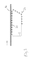
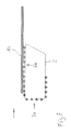
- FIGS. 1 to 10 are greatly simplified and show the basic principle of the invention in ten successive individual situations.
- 1a denotes a first and from FIG. 5 1b a second plate.
- the two plates 1 a, 1 b are wood-based panels, which are coated in a manner explained in more detail with reference to FIG 11 with a PU adhesive and then stuck to a honeycomb center layer of a sandwich panel on both sides.
- the finished sandwich element forms a lightweight board.
- the plates 1 a and 1 b are transported horizontally from left to right, which is also discussed in more detail with reference to FIG. 11.
- FIG. 1 shows a closed track with an upper horizontal track section 2, along which, as the figures as a whole show, two carrying devices each having ten rollers provided with rollers can be moved.
- the carrying devices are designated by 3a and 3b.
- the mentioned horizontal piece of the closed track 2 forms, when one of the carrying devices 3a, 3b thereon, a transport path.
- the first plate 1a arrives from the left and has already reached the transport path with its right front edge in FIG. Therefore, here the first carrying device 3a is already moved slightly upwards from the lower region of the closed transport path 2, so that its clockwise leading roller axis lies on the horizontal path piece.
- the first plate 1 a has already reached this foremost roll axis and covers it at the front just under.
- the second carrying device 3b is almost completely in the lower region of the closed transport path 2; only their clockwise rearmost roller axis lies in the horizontal track area.
- FIG. 2 shows how the first support device 3a moves with the first plate 1 a to the right to a connection to the rearmost end of the second support device 3b and finally the entire first support device 3a completely in the horizontal path piece to come to rest.
- the first carrying device 3a thus forms the transport path for the plates 1a and 1b. Accordingly, the first plate 1 a rolls from the time shown in Figure 2 to the right on the roles of the first carrying device 3 a and by the way also on the last role of the second carrying device 3 b to the right.
- the second carrying device 3b moves from the position shown in FIG. 3 directly in front of the first transport device 3a into the position shown in FIGS.
- Figures 5 and 6 show a transition between the plates 1 a and 1b "shock-to-shock".
- the plates can also be driven with certain gaps. Then, the gap should be symmetrically aligned with the front roller of the second carrying device 3b and the rear roller of the first carrying device 3a, so that with very thin plates which inevitably bend slightly, the plate edges can still mutually largely seal off each other without the top of the plate to seal off the other plate. In a butt-to-jerk mode of operation, this symmetry does not matter as much, but the impact should not be over either of the rollers, as shown in FIG. 6.
- FIG. 11 shows a somewhat more detailed illustration of the installation according to the invention for applying the adhesive.
- a roller conveyor of no further interest is shown, which transports the plates drawn in FIGS. 1 to 10 from the left of a stack. They are taken from the stack ("unstacked"), possibly trimmed, and then transported via the roller conveyor from the left approaching. 4 with a roller conveyor concluding the lack of double roller device 4 is called, which presses on the plates 1 a, 1 b from above and below and drives them in the sense of the movement shown in Figures 1 to 10 as long as the plate not with their rear edge of the double roller device 4 has run out.
- the system shown in FIG. 11 includes another roller conveyor, but here without an initial drive device, via which the plates are fed to a turning device, so that they can then be placed with the adhesive-coated side down onto the already described honeycomb middle layer of the sandwich board.
- the illustrated middle part initially shows the already shown in Figures 1 to 10 closed transport path 2. This corresponds to a projection of a total of four link chain tracks in the drawing plane.
- Two link chains each belong to a carrying device 3a and 3b, respectively. These are in the position shown in Figures 1 and 10.
- Each of the carrying devices 3a and 3b is provided with axes that extend perpendicular to the plane of the drawing over the entire width of the device and are mounted on the link chains. In the field of each roller three links of the link chain are drawn to illustrate this. Over the axial length of these axes they carry a plurality of roles, depending on the stability of the transported plates and the total width of the system.
- the link chains are driven by gears 5 in the deflection points of the closed transport path, again for the Weg.Tragevorraumen 3a and 3b independent gears and drives are provided.
- the rollers are frictionally mounted on the axles friction rollers. This has the advantage that the plates, when their rear edge has left the double-roller device 4, can be transported further to the right by a further movement of the carrying device 3a or 3b "responsible" for the respective plate, cf. FIGS. 5 and 6 and 8, 9 and 10.
- the reference numeral 6 denotes a frame construction of the system.
- An applicator 7 with a driven by a motor 8 plate 9 and a sprayer 10 is located above the transport path.
- the spraying device 10 sprays freshly mixed two-component PU adhesive fluid onto the rotating disk 9, which laterally ejects it in the manner shown in the drawing, reference numeral 11.
- the entire area of the moving over the transport path plates 1 a, 1 b are covered. This is done to avoid waste already before the arrival of the leading edge of the first plate 1a and beyond the trailing edge of the last plate 1b also.
- the polyol component must be switched off a little late in order to protect the line system from damage caused by hardening PU adhesive.
- the clockwise foremost role of the first support device 3a is protected by a splash guard 12, which is provided in the same way also on the foremost role of the second support device 3b.
- the rearmost role of the second support device 3b as drawn, no longer reached in this embodiment of the adhesive 11.
- the adhesive 11 is thus characterized by respective fenders 13 (vertically on the frame structure and, designated 14, obliquely in the right-hand area) and a drip pan 15 are collected. These can be covered with paper webs, so that the hardening adhesive can be removed at regular intervals without major inconvenience.
- the lateral and lower portions of the transport path 2 of the carrying devices 3a and 3b are protected by the fenders 13 and 14 and the tray 15.
- the foremost roll of the first carrying device 3a and the rearmost roll of the second carrying device 3b are already arranged at the height of the conveying path, which is not necessary. It would be possible to slightly increase the part of the transport path 2 that does not correspond to the transport path and thus bring both carrying devices 3a and 3b completely out of the transport path.
- the foremost roll of the first carrying device 3a is already in the position for receiving the front edge of a plate, as shown in Figure 1, and the rearmost roll of the second carrying device 3b supports a plate in transition to the right following roller conveyor, even if Incidentally, the first carrying device 3a is located in the transport path, cf. FIG. 3.
- FIG. 11 could be readily used in the case of control other than those shown in FIGS. 1 to 10, also for the mode of operation described as "oscillating" in the introductory description.
- Figure 3 starting that there would move the two carrying device 3a and 3b counterclockwise and the transport direction of the plate 1 a, so that the situation would arise from Figure 4 with reversed carrying devices 3a and 3b, ie with the second carrying device 3b in the transport path and the first carrying device 3a in the protected area.
Landscapes
- Coating Apparatus (AREA)
- Veneer Processing And Manufacture Of Plywood (AREA)
- Laminated Bodies (AREA)
Abstract
Description
- Diese Erfindung bezieht sich auf eine Anlage zum Auftragen von Flüssigkeiten auf Platten, in der die Platten während des Flüssigkeitsauftrages durch eine Tragevorrichtung gehalten werden.
- In vielen Produktionsverfahren müssen plattenartige Elemente mit Flüssigkeiten versehen werden. Beispiele sind Lack- oder Klebstoffauftrag. Als Platten kommen unterschiedlichste flache Materialien in Betracht, im Rahmen dieser Erfindung bevorzugt Platten für die Bauindustrie, etwa zur Herstellung von aus zwei oder mehr Lagen hergestellten Sandwichbauplatten. Die Platten können also beispielsweise Holzplatten oder Holzwerkstoffplatten, Blechplatten, Laminatplatten und andere sein.
- Die Erfindung geht dabei von einer Auftragsvorrichtung für die Flüssigkeit aus, die die Flüssigkeit von oben auf die Platten aufträgt, was hier im Sinne der Schwerkraft gemeint ist, jedoch nicht notwendigerweise präzise vertikal bedeuten muss. Die Auftragsvorrichtung sprüht, spritzt oder gießt also die Flüssigkeit so auf, dass sich diese mit einer Bewegungskomponente in Richtung der Schwerkraft auf den Platten verteilt.
- Dabei sollen die Platten an der Auftragsvorrichtung vorbei bewegt werden. Diese Bewegungsbahn wird im Folgenden als Transportbahn bezeichnet. Anhand des Flüssigkeitsauftrages selbst können die Platten still stehen, werden aber vorzugsweise weiterbewegt, sodass auch die Bewegung der Platten zu der gewünschten Verteilung der Flüssigkeit beiträgt. Währenddessen werden die Platten von einer Tragevorrichtung unterstützt.
- Der Erfindung liegt das Problem zugrunde, eine verbesserte Flüssigkeitsauftragsanlage des beschriebenen Typs anzugeben.
- Das Problem wird gelöst durch eine Anlage zum Auftragen von Flüssigkeit auf Platten, die aufeinander folgend über eine Transportbahn transportiert werden, mit einer Auftragsvorrichtung, die die Flüssigkeit von oben auf die Platten aufträgt, und einer Tragevorrichtung unter der Auftragsvorrichtung, die zum Tragen der Platten in der Transportbahn ausgelegt ist, dadurch gekennzeichnet, dass die Tragevorrichtung aus der Transportbahn heraus in einen Bereich bewegt werden kann, der, wenn keine Platte vorhanden ist, vor Flüssigkeitsauftrag geschützt ist, sowie durch ein entsprechendes Verfahren zum Auftragen von Flüssigkeit auf Platten.
- Bevorzugte Ausgestaltungen sind in den abhängigen Ansprüchen angegeben und werden im Folgenden näher erläutert. Dabei beziehen sich alle Merkmale implizit sowohl auf die Vorrichtungskategorie als auch auf die Verfahrenskategorie der Erfindung.
- Die Tragevorrichtung ist erfindungsgemäß selbst beweglich ausgelegt, und zwar so, dass sie aus einem, jedenfalls bei Lücken zwischen den Platten oder bei Abwesenheit von Platten, vom Flüssigkeitsauftrag potenziell betroffenen Bereich heraus in einen geschützten Bereich bewegt werden kann. Die Erfinder haben nämlich erkannt, dass eine Kontamination der Tragevorrichtung mit Flüssigkeit, beispielsweise mit Lack oder Klebstoff, zu größeren Schwierigkeiten bei Betrieb und Wartung führen kann und andererseits praktische Nachteile entstehen, wenn die Steuerung der Auftragsvorrichtung so erfolgt, dass solche Kontamination allein durch die Abstimmung auf die Plattenbewegung vermieden wird. Solche Nachteile können in einem Verschnitt am Anfang oder am Ende einer Platte oder Plattenreihe durch etwas verspätetes Einschalten oder etwas verfrühtes Ausschalten der Auftragsvorrichtung zur Vermeidung einer solchen Kontamination vor dem Anfang oder hinter dem Ende der Platte oder Plattenreihe bestehen. Sie können in der zunehmenden Komplexität der Steuerung der Auftragsvorrichtung bestehen. Sie können auch in der Notwendigkeit besonders knapper Passungen zwischen aufeinander folgenden Platten zur Vermeidung einer Kontamination dazwischen bestehen.
- Stattdessen soll nun erfindungsgemäß die Tragevorrichtung aus dem gefährdeten Bereich wegbewegt werden. Damit kann erreicht werden, dass am Plattenanfang vor der Plattenvorderkante bzw. am Plattenende hinter der Plattenhinterkante keine gefährdeten Teile der Tragevorrichtung exponiert sind und die Auftragsvorrichtung damit jedenfalls soweit frühzeitiger eingeschaltet bzw. weiter betrieben wird, dass die Platten vollständig von Anfang an bzw. bis zum Ende erfasst werden. Dies gilt für den Anfang und das Ende einer ganzen Plattenreihe und / oder auch für aufeinander folgende und knapp beabstandete Platten, wenn der Plattenzwischenraum ein Problem darstellt.
- Eine bevorzugte Gestaltung der Tragevorrichtung weist Rollen auf, über die die Platten auf der Tragevorrichtung abrollen können. Die Rollenachsen liegen damit quer zu der Transportrichtung der Platten in der Transportbahn und die Rollen selbst sind in dieser Transportrichtung voneinander beabstandet. Eine solche erfindungsgemäß bewegliche Rollenbahn kann etwa über einen Kettenzug bewegt und in einer Schiene geführt werden. Die Erfindung ist jedoch nicht auf Rollenkonstruktionen eingeschränkt, beispielsweise käme auch eine Bahn aus in Kombination mit den Platten gleitfähigem Material in Betracht, über die die Platten einfach hinweg gleiten. Die Tragevorrichtung muss, auch in ihrer Ausführung mit Rollen, nicht notwendigerweise für den Vortrieb der Platten sorgen. Vielmehr kann dieser auch in anderer Weise, insbesondere außerhalb der eigentlichen Transportbahn unter der Auftragsvorrichtung, gewährleistet werden, wozu auf das Ausführungsbeispiel verwiesen wird.
- Die Beweglichkeit der Tragevorrichtung ist vorzugsweise ebenfalls in der Transportrichtung der Platten in der Transportbahn orientiert, wobei der geschützte Bereich zumindest zum Teil unter der Transportbahn angeordnet ist. Dann kann die Tragevorrichtung an den Enden der Transportbahn in den geschützten Bereich "abtauchen" bzw. wieder aus ihm herausbewegt werden.
- Bevorzugt sind Friktionsrollen, die mit einem gewissen Reibwiderstand in ihren Lagern laufen. Einerseits können mit anderen Antriebsvorrichtungen angetriebene Platten über die Friktionsrollen abrollen. Andererseits kann die Tragevorrichtung bei einer Bewegung in der Transportrichtung der Platten die Platten infolge des Reibwiderstands in den Rollenlagern auch mitnehmen, etwa wenn diese aus einer Antriebsvorrichtung stromaufwärts von der Flüssigkeitsauftragsanlage heraus gelaufen sind.
- Die Auftragsvorrichtung kann eine Sprühdüse oder ein Gießauslauf sein, beide insbesondere auch quer zur Transportrichtung bewegt. Bevorzugt ist jedoch ein rotierender Teller, auf den die Flüssigkeit von oben aufgebracht wird und der die Flüssigkeit infolge der Rotation am Rand wegschleudert. Ein solcher Schleuderteller ist in der Regel abgesehen von seiner Rotation unbeweglich über der Transportbahn angebracht, könnte aber auch bewegt sein. Eine Auftragsvorrichtung mit einem solchen Schleuderteller ist beispielsweise in der europäischen Patentanmeldung mit dem Aktenzeichen
06 110 019.4 - Besonders bevorzugte Ausgestaltungen der Tragevorrichtung sind zweigeteilt, sodass also zwei Tragevorrichtungen im obigen Sinn vorliegen. Sie eignen sich besonders für eine Betriebsweise, bei der nicht nur am Anfang und am Ende einer Plattenreihe oder einer einzelnen Platte die Kontamination der Tragevorrichtung vermieden werden soll, sondern auch in Lücken zwischen aufeinander folgenden Platten einer Reihe.
- Bei einer ersten Ausgestaltung sind die Tragevorrichtungen für eine oszillierende Bewegung ausgelegt, wobei die Lücken zwischen den Platten jeweils über Lücken zwischen den Tragevorrichtungen liegen und die Bewegungen der Lücken aufeinander abgestimmt sind. Dabei könnte sich die Tragevorrichtung mit einer in der Transportbahn bewegten Platte mitbewegen, wobei die Vorderkante der Tragevorrichtung nicht vor der Platte hervorläuft, also beispielsweise die Tragevorrichtung synchron mit der Plattenvorderkante mitgeführt wird. Die Tragevorrichtung kann stoppen, insbesondere dann, wenn die Vorderkante am Rand der Transportbahn angekommen ist, wobei dann die Platte relativ zu der Tragevorrichtung weiterbewegt werden kann, insbesondere auf ihr abrollen kann.
- Bei der hier beschriebenen ersten bevorzugten Ausgestaltung bewegt sich die Tragevorrichtung so rechtzeitig in der zu der Transportrichtung entgegengesetzten Richtung zurück, bevor die Hinterkante der Platte die Transportbahn erreicht, dass die zweite Tragevorrichtung, die von der Vorderseite der Transportbahn kommend aus dem geschützten Bereich heraus bewegt wird, die Platte gewissermaßen "übernimmt". Wenn nun die Hinterkante der Platte ankommt, kann sich die Hinterkante der Tragevorrichtung mit dieser nach vorne bewegen, wobei sie nicht hinter der Plattenhinterkante herläuft, um Kontaminationen zu vermeiden. Dabei kann die erste, zuvor in dem geschützten Bereich untergebrachte Tragevorrichtung nun wieder mit einer geeigneten Lücke zu der Hinterkante der zweiten Tragevorrichtung in die Transportbahn bewegt werden, und zwar abgestimmt auf die nächste Platte und deren Vorderkante.
- Hierbei werden also die Tragevorrichtungen in einer oszillierenden Bewegung mit Richtungsumkehr unter der Platte vertauscht, während die Platte in der Transportbahn liegt. Dadurch kann beim Herannahen einer Plattenhinterkante die Hinterkante einer gerade diese Platte tragenden Tragevorrichtung mit dieser Plattenhinterkante vorbewegt werden, während eine andere Tragevorrichtung mit ihrer Vorderkante auf die Vorderkante der folgenden Platte abgestimmt bewegt werden kann.
- Bei einer zweiten Ausgestaltung mit (zumindest) zwei Tragevorrichtungen wird wieder eine der beiden Tragevorrichtungen mit der Vorderkante einer Platte in die Transportbahn und unter die Auftragsvorrichtung bewegt, wobei wiederum die Vorderkante der Tragevorrichtung nicht vor der Plattenvorderkante hervorläuft. Auch hier kann es bei längeren Platten zu einem Zwischenstopp kommen, etwa wenn die Vorderkante der Tragevorrichtung am Rand der Transportbahn angekommen ist. Im Gegensatz zur obigen Erläuterung wird jedoch diese Tragevorrichtung danach nicht mehr in entgegengesetzter Richtung bewegt, sondern bewegt sich weiterhin im Sinn der Transportrichtung in den geschützten Bereich, wenn die Hinterkante der Platte kommt, wobei die Hinterkante der Tragevorrichtung wiederum nicht hinter der Plattenhinterkante herläuft. Es bleibt also bei einer Zuordnung dieser Tragevorrichtung zu der entsprechenden Platte.
- Die zweite Tragevorrichtung kommt dann aus dem geschützten Bereich in gleicher Weise auf die folgende Platte abgestimmt, und zwar wiederum mit den jeweiligen Vorderkanten, während die erste Tragevorrichtung durch den geschützten Bereich so weiterbewegt wird, dass sie mit der übernächsten Platte wieder eingesetzt werden kann. Hier ist also ein geschlossener Transportweg der Transportvorrichtung im geschützten Bereich notwendig, weswegen man hier von einer drehsinnerhaltenden Bewegung sprechen kann. Bei der vorherigen Ausgestaltung kann es ebenfalls einen geschlossenen Transportweg geben, wenngleich dieser nicht notwendig ist. Bei einem geschlossenen Weg kann man dort von einer Drehsinnumkehr sprechen, bei einem nicht geschlossenen Weg jedenfalls von abwechselnden Bewegungsrichtungen.
- Übrigens könnten die Randelemente der Tragevorrichtungen abweichend von den übrigen Rollen gestaltet sein, etwa um besonders knapp an einer Plattenkante einen Unterstützungspunkt zur Verfügung stellen zu können, ohne damit einem Verschmutzungsrisiko zu unterliegen. Sie können insbesondere auch ohne Rollen ausgestaltet sein, etwa nur als starre Trageelemente. In den Situationen, in denen die Platten über die Rollen abrollen sollen, könnten die Tragevorrichtungen dann so positioniert sein, dass diese starren Trageelemente etwas aus der Transportbahn abgesenkt sind. Sie kämen dann nur zur Funktion, wenn eine der Tragevorrichtungen mit einer Vorderkante oder Hinterkante der Platte mitläuft und damit zwischen der Plattenbewegung und der Tragevorrichtungsbewegung keine Differenzgeschwindigkeiten auftreten müssen.
- Die beiden Tragevorrichtungen werden vorzugsweise mit ihren jeweiligen Kanten bezüglich der Lücken zwischen den Platten symmetrisch gehalten. Dies hat den Vorteil, dass sich die Plattenenden, jedenfalls bei dünneren Platten, in einem nicht mehr unterstützten Randbereich symmetrisch herabbiegen. Damit kann erreicht werden, dass sich die Plattenstirnseiten gegenseitig vor Flüssigkeitsauftrag abschirmen, um Kantenkontaminationen an den Platten zu vermeiden.
- Die Erfindung betrifft ferner eine Anlage zum Herstellen von Sandwichbauplatten aus zumindest zwei Schichten, in der eine Flüssigkeitsauftragsanlage mit einer oder einer Mehrzahl erfindungsgemäßer Tragevorrichtungen inbegriffen ist. Diese Anlage könnte beispielsweise vorgeschaltete Schneidevorrichtungen zum Zuschneiden der benötigten Formatzuschnitte der einzelnen Schichten aufweisen, die erfindungsgemäße Flüssigkeitsauftragsanlage zum Aufbringen von Klebstoff auf Deckschichten verwenden und nachgeschaltet diese Deckschichten auf Zwischenschichten aufsetzen oder die Zwischenschichten auf die Deckschichten aufsetzen, um diese dann z. B. mit einer Doppelbandanlage zusammenzupressen.
- Im Folgenden wird die Erfindung anhand eines Ausführungsbeispiels näher erläutert,
wobei die einzelnen Merkmale auch in anderen Kombinationen erfindungswesentlich sein können und sich implizit sowohl auf die Vorrichtungskategorie als auch auf die Verfahrenskategorie der Erfindung beziehen. - Figuren 1 bis 10
- zeigen in stark schematisierten Einzeldarstellungen die Funktionsweise einer erfindungsgemäßen Anlage und das erfindungsgemäße Verfahren in zeitlichem Ablauf.
- Figur 11
- zeigt eine vereinfachte Aufrissdarstellung der erfindungsgemäßen Anlage.
- Die Figuren 1 bis 10 sind stark vereinfacht und zeigen in zehn aufeinander folgenden Einzelsituationen das Grundprinzip der Erfindung. Dabei ist mit 1a eine erste und ab Figur 5 mit 1b eine zweite Platte bezeichnet. Die beiden Platten 1 a, 1b sind Holzwerkstoffplatten, die in einer anhand Figur 11 näher erläuterten Weise mit einem PU-Klebstoff zu beschichten und dann auf eine Wabenmittelschicht einer Sandwichplatte beidseits aufzukleben sind. Das fertige Sandwichelement bildet eine Leichtbauplatte. Die Platten 1 a und 1b werden von links nach rechts horizontal transportiert, worauf anhand Figur 11 ebenfalls noch näher eingegangen wird.
- Figur 1 zeigt eine geschlossene Bahn mit einem oberen horizontalen Bahnabschnitt 2, entlang der, wie die Figuren insgesamt zeigen, zwei Tragevorrichtungen mit jeweils zehn mit Rollen versehenen Achsen bewegt werden können. Die Tragevorrichtungen sind mit 3a und 3b bezeichnet. Das erwähnte horizontale Stück der geschlossenen Bahn 2 bildet dann, wenn sich eine der Tragevorrichtungen 3a, 3b darauf befindet, eine Transportbahn.
- In Figur 1 kommt die erste Platte 1a von links an und hat mit ihrer in Figur 1 rechten Vorderkante bereits die Transportbahn erreicht. Daher ist hier die erste Tragevorrichtung 3a bereits etwas aus dem unteren Bereich des geschlossenen Transportwegs 2 nach oben bewegt, sodass ihre im Uhrzeigersinn vorderste Rollenachse auf dem horizontalen Bahnstück liegt. Die erste Platte 1 a hat diese vorderste Rollenachse bereits erreicht und deckt sie vorne knapp ab. Gleichzeitig befindet sich die zweite Tragevorrichtung 3b fast vollständig im unteren Bereich des geschlossenen Transportwegs 2; nur noch ihre im Uhrzeigersinn hinterste Rollenachse liegt im horizontalen Bahnbereich.
- Der Übergang von Figur 1 zu Figur 2 zeigt, wie sich die erste Tragevorrichtung 3a mit der ersten Platte 1 a nach rechts bis zu einem Anschluss an das hinterste Ende der zweiten Tragevorrichtung 3b bewegt und dabei schließlich die gesamte erste Tragevorrichtung 3a vollständig in dem horizontalen Bahnstück zu liegen kommt. In Figur 2 und auch in den folgenden Figuren 3, 4 und 5 bildet damit die erste Tragevorrichtung 3a die Transportbahn für die Platten 1a und 1 b. Dementsprechend rollt die erste Platte 1 a ab dem in Figur 2 dargestellten Zeitpunkt nach rechts über die Rollen der ersten Tragevorrichtung 3a und übrigens auch über die letzte Rolle der zweiten Tragevorrichtung 3b nach rechts ab. Währenddessen bewegt sich die zweite Tragevorrichtung 3b aus der in Figur 3 gezeigten Lage direkt vor der ersten Transportvorrichtung 3a in die in Figur 4 und 5 gezeigte Lage direkt dahinter. In Figur 5 ist bereits eine zweite nachfolgende Platte 1b zu sehen, die mit einem geringen, zeichnerisch nicht dargestellten Kantenabstand der ersten Platte 1a nachfolgt. In Figur 5 beginnt die zweite Tragevorrichtung 3b der Vorderkante der zweiten Platte 1b zu folgen, wobei die erste Tragevorrichtung 3a dementsprechend vorweg läuft. Damit wird schließlich die in Figur 7 dargestellte Situation erreicht, in der die zweite Tragevorrichtung 3b vollständig die Transportbahn bildet.
- Die Figuren 5 und 6 zeigen einen Übergang zwischen den Platten 1 a und 1b "Stoß-an-Stoß". Die Platten können aber auch mit gewissen Lücken gefahren werden. Dann sollte die Lücke symmetrisch auf die vordere Rolle der zweiten Tragevorrichtung 3b und die hintere Rolle der ersten Tragevorrichtung 3a ausgerichtet sein, so dass bei sehr dünnen Platten, die sich zwangsläufig etwas biegen, die Plattenkanten sich dennoch gegenseitig weitgehend abschotten können, ohne jeweils die Plattenoberseite der anderen Platte abzuschotten. Bei einer Stoß-an-Stoß-Betriebsweise kommt es auf diese Symmetrie nicht in dem Maße an, jedoch sollte der Stoß nicht über einer der beiden Rollen liegen, wir Figur 6 auch zeigt.
- Wenn man nun von Figur 7 wieder zu Figur 5 springt, kann man sich leicht den Weitertransport einer größeren Zahl von Platten vorstellen. Die folgenden Figuren 8 bis 10 zeigen das Auslaufen einer letzten Platte, hier der Einfachheit halber schon der zweiten Platte 1b, ähnlich wie die Figuren 1 und 2 das Einlaufen einer ersten Platte ohne vorhergehende Platte zeigen. Dabei läuft in den Figuren 8 bis 10 die hintere Rollenachse der zweiten Tragevorrichtung 3b mit der hinteren Kante der zweiten Platte 1 b mit, wobei sie wiederum von der Plattenkante etwas abgedeckt wird. In Figur 10 ist für die beiden Tragevorrichtungen 3a und 3b wieder die Situation aus Figur 1 erreicht. Wenn man also von Figur 10 zu Figur 1 springt, springt man von dem Auslaufen der letzten Platte in der Reihe knapp beabstandeter Platten zu dem Einlaufen der ersten Platte einer neuen Reihe oder vom Produktionsende zum Produktionsstart.
- Figur 11 zeigt eine etwas detailliertere Darstellung der erfindungsgemäßen Anlage zum Auftragen des Klebstoffs.
- Im linken Bereich ist eine nicht weiter interessierende Rollenbahn dargestellt, die die in den Figuren 1 bis 10 gezeichneten Platten von links von einem Stapel heran transportiert. Sie werden aus dem Stapel entnommen ("entstapelt"), gegebenenfalls noch besäumt, und dann über die Rollenbahn von links kommend heran transportiert. Mit 4 ist dabei eine die Rollenbahn abschließende mangelartige Doppelrollenvorrichtung 4 bezeichnet, die auf die Platten 1 a, 1b von oben und von unten drückt und diese im Sinne der in den Figuren 1 bis 10 gezeigten Bewegung so lange antreibt, wie die Platte nicht mit ihrer hinteren Kante aus der Doppelrollenvorrichtung 4 heraus gelaufen ist.
- Rechts schließt an die in Figur 11 dargestellte Anlage eine weitere Rollenbahn, hier aber ohne anfängliche Antriebsvorrichtung, an, über die die Platten einer Wendevorrichtung zugeführt werden, sodass sie dann mit der klebstoffbeschichteten Seite nach unten auf die bereits beschriebene Wabenmittelschicht der Sandwichbauplatte aufgelegt werden können.
- Der dargestellte mittlere Teil zeigt zunächst den bereits in den Figuren 1 bis 10 dargestellten geschlossenen Transportweg 2. Dieser entspricht einer Projektion von insgesamt vier Gliederkettenbahnen in die Zeichenebene. Jeweils zwei Gliederketten gehören zu je einer Tragevorrichtung 3a bzw. 3b. Diese befinden sich in der in den Figuren 1 und 10 dargestellten Lage. Jede der Tragevorrichtungen 3a und 3b ist dabei mit senkrecht zu der Zeichenebene über die ganze Breite der Vorrichtung durchgehenden Achsen versehen, die an den Gliederketten montiert sind. Im Bereich der einzelnen Rollen sind jeweils drei Glieder der Gliederkette gezeichnet, um dies zu veranschaulichen. Über die axiale Länge dieser Achsen tragen diese eine Mehrzahl Rollen, und zwar abhängig von der Stabilität der zu transportierenden Platten und der Gesamtbreite der Anlage. Die Gliederketten werden über Zahnräder 5 in den Umlenkpunkten des geschlossenen Transportwegs angetrieben, wobei wiederum für die beiden.Tragevorrichtungen 3a und 3b voneinander unabhängige Zahnräder und Antriebe vorgesehen sind.
- Bei den Rollen handelt es sich um reibschlüssig auf den Achsen gelagerte Friktionsrollen. Dies hat den Vorteil, dass die Platten dann, wenn ihre hintere Kante die Doppelrollenvorrichtung 4 verlassen hat, durch eine Weiterbewegung der dann für die jeweilige Platte "zuständigen" Tragevorrichtung 3a oder 3b weiter nach rechts transportiert werden können, vgl. die Figuren 5 und 6 sowie 8, 9 und 10.
- Das Bezugszeichen 6 bezeichnet eine Rahmenkonstruktion der Anlage.
- Über der Transportbahn ist eine Auftragsvorrichtung 7 mit einem von einem Motor 8 angetriebenen Teller 9 und einer Sprüheinrichtung 10 eingezeichnet. Die Sprüheinrichtung 10 sprüht frisch angemischte Zweikomponenten-PU-Klebstoffflüssigkeit auf den rotierenden Teller 9, der diese in der zeichnerisch dargestellten Weise, Bezugszeichen 11, seitlich wegschleudert. Damit kann der gesamte Bereich der über die Transportbahn bewegten Platten 1 a, 1b abgedeckt werden. Dies geschieht zur Vermeidung von Verschnitt schon vor dem Ankommen der Vorderkante der ersten Platte 1a und noch über die Hinterkante der letzten Platte 1b hinaus. Beispielsweise muss bei PU-Gemischen die Polyol-Komponente etwas verspätet ausgeschaltet werden, um das Leitungssystem vor Schäden durch aushärtenden PU-Klebstoff zu bewahren.
- In der in Figur 11 dargestellten Situation ist die im Uhrzeigersinn vorderste Rolle der ersten Tragevorrichtung 3a durch ein Spritzschutzblech 12 geschützt, das in gleicher Weise auch an der vordersten Rolle der zweiten Tragevorrichtung 3b vorgesehen ist. Die hinterste Rolle der zweiten Tragevorrichtung 3b wird, wie gezeichnet, bei dieser Ausführungsform von dem Klebstoff 11 nicht mehr erreicht. Wenn, wie in Figur 11 dargestellt, keine Platte vorhanden ist, wird der Klebstoff 11 damit von entsprechenden Schutzblechen 13 (vertikal an der Rahmenkonstruktion und, mit 14 bezeichnet, im rechten Bereich schräg) sowie einer Auffangwanne 15 gesammelt. Diese können mit Papierbahnen belegt sein, sodass der darauf erhärtende Klebstoff in regelmäßigen Abständen ohne größere Umstände entfernt werden kann. Die seitlichen und unteren Bereiche des Transportwegs 2 der Tragevorrichtungen 3a und 3b sind durch die Schutzbleche 13 und 14 und die Wanne 15 geschützt.
- Übrigens sind in diesem Beispiel die vorderste Rolle der ersten Tragevorrichtung 3a und die hinterste Rolle der zweiten Tragevorrichtung 3b bereits auf der Höhe der Transportbahn angeordnet, was nicht notwendig ist. Man könnte den nicht der Transportbahn entsprechenden Teil des Transportwegs 2 ohne Weiteres etwas vergrößern und damit beide Tragevorrichtungen 3a und 3b ganz aus der Transportbahn bringen. In diesem Fall liegt die vorderste Rolle der ersten Tragevorrichtung 3a bereits in der Position zur Aufnahme der vorderen Kante einer Platte, wie in Figur 1 gezeigt, und unterstützt die hinterste Rolle der zweiten Tragevorrichtung 3b eine Platte im Übergang zu der rechts folgenden Rollenbahn, auch wenn im Übrigen die erste Tragevorrichtung 3a in der Transportbahn liegt, vgl. Figur 3.
- Die Anlage aus Figur 11 könnte bei von den Figuren 1 bis 10 abweichender Steuerung ohne Weiteres auch für die in der einleitenden Beschreibung als "oszillierend" bezeichnete Betriebsweise verwendet werden. Hierzu müsste man sich von Figur 3 ausgehend vorstellen, dass sich dort die beiden Tragevorrichtung 3a und 3b entgegen dem Uhrzeigersinn und der Transportrichtung der Platte 1 a bewegen würden, sodass die Situation aus Figur 4 mit vertauschten Tragevorrichtungen 3a und 3b entstehen würde, also mit der zweiten Tragevorrichtung 3b in der Transportbahn und der ersten Tragevorrichtung 3a im geschützten Bereich. Dies würde, mit vertauschten Tragevorrichtungen 3a und 3b, dann sinngemäß für die Figuren 5 und 6 gelten. Im Übergang von Figur 6 zu Figur 7 würde sich wieder eine Bewegung beider Tragevorrichtungen 3a und 3b entgegen dem Uhrzeigersinn und der Transportrichtung der Platten 1 a und 1b ergeben, sodass die beiden Tragevorrichtungen auch in den Figuren 7 bis 10 vertauscht wären. Im Übrigen würden die bisherigen Erläuterungen zu den Figuren gelten.
Claims (14)
- Anlage zum Auftragen von Flüssigkeit (11) auf Platten (1a, 1b), die aufeinander folgend über eine Transportbahn (2) transportiert werden,
mit einer Auftragsvorrichtung (7 - 10), die die Flüssigkeit (11) von oben auf die Platten (1 a, 1 b) aufträgt,
und einer Tragevorrichtung (3a, 3b) unter der Auftragsvorrichtung (7 - 10), die zum Tragen der Platten (1a, 1 b) in der Transportbahn (2) ausgelegt ist,
dadurch gekennzeichnet, dass die Tragevorrichtung (3a, 3b) aus der Transportbahn (2) heraus in einen Bereich bewegt werden kann, der, wenn keine Platte vorhanden ist, vor Flüssigkeitsauftrag geschützt ist. - Anlage nach Anspruch 1, bei der die Tragevorrichtung (3a, 3b) in der Transportrichtung der Transportbahn (2) beabstandete Rollen aufweist.
- Anlage nach Anspruch 2, bei der die Rollen Friktionsrollen sind.
- Anlage nach einem der vorstehenden Ansprüche, bei der die Tragevorrichtung (3a, 3b) in der Transportrichtung der Platten (1a, 1b) in der Transportbahn (2) beweglich ist und der geschützte Bereich teilweise unter der Transportbahn (2) angeordnet ist.
- Anlage nach einem der vorstehenden Ansprüche, bei der die Auftragsvorrichtung (7-10) einen rotierenden Teller (9) für einen Schleuderauftrag der Flüssigkeit (11) aufweist.
- Anlage nach einem der vorstehenden Ansprüche, bei der zwei Tragevorrichtungen (3a, 3b) vorgesehen sind.
- Anlage nach Anspruch 6, bei der die Tragevorrichtungen (3a, 3b) für eine oszillierende Bewegung ausgelegt sind, wobei bei der oszillierenden Bewegung die Lücken zwischen den Tragevorrichtungen (3a, 3b) auf die Lücken zwischen den Platten (1 a, 1 b) abgestimmt sind.
- Anlage nach Anspruch 6, bei der die Tragevorrichtungen (3a, 3b) für eine drehsinnerhaltende Bewegung entlang eines geschlossenen Transportweges (2) ausgelegt sind, wobei bei dieser Bewegung die Lücken zwischen den Tragevorrichtungen (3a, 3b) auf die Lücken zwischen den Platten (1a, 1b) abgestimmt sind.
- Anlage zum Herstellen von Sandwichbauplatten, die eine Anlage nach einem der vorstehenden Ansprüche beinhaltet.
- Verfahren zum Auftragen von Flüssigkeit (11) auf Platten (1 a, 1 b),
bei dem die Platten (1a, 1b) aufeinander folgend über eine Transportbahn (2) transportiert werden
und die Flüssigkeit (11) mit einer Auftragsvorrichtung (7 - 10) von oben auf die Platten (1a, 1b) aufgetragen wird,
dadurch gekennzeichnet, dass die Platten (1a, 1b) in der Transportbahn (2) mit einer Tragevorrichtung (3a, 3b) unter der Auftragsvorrichtung (7 - 10) gehalten werden,
die bei Lücken zwischen den Platten (1a, 1b) oder dann, wenn keine Platte vorhanden ist, aus der Transportbahn (2) heraus in einen Bereich bewegt wird, der dann vor Flüssigkeitsauftrag geschützt ist. - Verfahren nach Anspruch 10 unter Verwendung einer Anlage nach Anspruch 6, bei dem die jeweiligen Enden der Tragevorrichtungen (3a, 3b) an den Lücken in Bezug auf die Lücken zwischen den Platten (1a, 1b) symmetrisch gehalten werden.
- Verfahren nach Anspruch 10 oder 11, bei dem die Flüssigkeit (11) ein Klebstoff, insbesondere PU-Klebstoff ist.
- Verfahren nach einem der Ansprüche 10 bis 12 unter Verwendung einer Anlage nach einem der Ansprüche 2 bis 10.
- Anlage nach einem der Ansprüche 1 bis 9, ausgelegt für ein Verfahren nach einem der Ansprüche 10 bis 12.
Priority Applications (4)
| Application Number | Priority Date | Filing Date | Title |
|---|---|---|---|
| DE502006005990T DE502006005990D1 (de) | 2006-11-09 | 2006-11-09 | Vorrichtung und Verfahren zum verschmutzungsfreien Auftrag von Flüssigkeiten auf Decklagen im Zuge der Herstellung von Sandwichplatten |
| AT06123771T ATE455598T1 (de) | 2006-11-09 | 2006-11-09 | Vorrichtung und verfahren zum verschmutzungsfreien auftrag von flüssigkeiten auf decklagen im zuge der herstellung von sandwichplatten |
| EP06123771A EP1920848B1 (de) | 2006-11-09 | 2006-11-09 | Vorrichtung und Verfahren zum verschmutzungsfreien Auftrag von Flüssigkeiten auf Decklagen im Zuge der Herstellung von Sandwichplatten |
| ES06123771T ES2339586T3 (es) | 2006-11-09 | 2006-11-09 | Dispositivo y procedimiento para la aplicacion sin contaminacion de liquidos sobre sustratos en el curso de la fabricacion de paneles de sandwich. |
Applications Claiming Priority (1)
| Application Number | Priority Date | Filing Date | Title |
|---|---|---|---|
| EP06123771A EP1920848B1 (de) | 2006-11-09 | 2006-11-09 | Vorrichtung und Verfahren zum verschmutzungsfreien Auftrag von Flüssigkeiten auf Decklagen im Zuge der Herstellung von Sandwichplatten |
Publications (2)
| Publication Number | Publication Date |
|---|---|
| EP1920848A1 true EP1920848A1 (de) | 2008-05-14 |
| EP1920848B1 EP1920848B1 (de) | 2010-01-20 |
Family
ID=37600893
Family Applications (1)
| Application Number | Title | Priority Date | Filing Date |
|---|---|---|---|
| EP06123771A Not-in-force EP1920848B1 (de) | 2006-11-09 | 2006-11-09 | Vorrichtung und Verfahren zum verschmutzungsfreien Auftrag von Flüssigkeiten auf Decklagen im Zuge der Herstellung von Sandwichplatten |
Country Status (4)
| Country | Link |
|---|---|
| EP (1) | EP1920848B1 (de) |
| AT (1) | ATE455598T1 (de) |
| DE (1) | DE502006005990D1 (de) |
| ES (1) | ES2339586T3 (de) |
Citations (4)
| Publication number | Priority date | Publication date | Assignee | Title |
|---|---|---|---|---|
| US3876465A (en) * | 1973-03-12 | 1975-04-08 | Zenith Radio Corp | Method and apparatus for coating skirtless cathode ray tube panels |
| US4041898A (en) * | 1975-10-29 | 1977-08-16 | Osaka Welding Industrial Co., Ltd. | Metal spraying apparatus |
| US5368643A (en) * | 1991-11-13 | 1994-11-29 | Ciba-Geigy Corporation | Coating apparatus for boards |
| DE10008890A1 (de) * | 2000-02-25 | 2001-09-13 | Eisenmann Lacktechnik Kg | Lackiervorrichtung |
-
2006
- 2006-11-09 EP EP06123771A patent/EP1920848B1/de not_active Not-in-force
- 2006-11-09 DE DE502006005990T patent/DE502006005990D1/de active Active
- 2006-11-09 ES ES06123771T patent/ES2339586T3/es active Active
- 2006-11-09 AT AT06123771T patent/ATE455598T1/de active
Patent Citations (4)
| Publication number | Priority date | Publication date | Assignee | Title |
|---|---|---|---|---|
| US3876465A (en) * | 1973-03-12 | 1975-04-08 | Zenith Radio Corp | Method and apparatus for coating skirtless cathode ray tube panels |
| US4041898A (en) * | 1975-10-29 | 1977-08-16 | Osaka Welding Industrial Co., Ltd. | Metal spraying apparatus |
| US5368643A (en) * | 1991-11-13 | 1994-11-29 | Ciba-Geigy Corporation | Coating apparatus for boards |
| DE10008890A1 (de) * | 2000-02-25 | 2001-09-13 | Eisenmann Lacktechnik Kg | Lackiervorrichtung |
Also Published As
| Publication number | Publication date |
|---|---|
| DE502006005990D1 (de) | 2010-03-11 |
| EP1920848B1 (de) | 2010-01-20 |
| ATE455598T1 (de) | 2010-02-15 |
| ES2339586T3 (es) | 2010-05-21 |
Similar Documents
| Publication | Publication Date | Title |
|---|---|---|
| DE3248788C2 (de) | Vorrichtung zum Drehen eines Gegenstandes um einen gegebenen Winkel um eine vertikale Achse | |
| EP3049198B2 (de) | Vorrichtung und verfahren zur führung von metallbändern mit schleisskörpern | |
| DE10119508C1 (de) | Materialführungssystem für Spleißmaschinen | |
| DE1806888A1 (de) | Foerdervorrichtung zum Ausrichten von Gegenstaenden | |
| EP0677473B1 (de) | Vorrichtung zum Falten oder dgl. von Blattlagen | |
| WO1995022498A1 (de) | Vorrichtung zum ablösen eines produktes von einem endlos umlaufenden band | |
| EP1920848B1 (de) | Vorrichtung und Verfahren zum verschmutzungsfreien Auftrag von Flüssigkeiten auf Decklagen im Zuge der Herstellung von Sandwichplatten | |
| DE102009036499A1 (de) | Bahnführungsvorrichtung zum Führen einer flexiblen Materialbahn | |
| DE602004004205T3 (de) | Automatisches System zum Sortieren und Palettieren von Artikeln | |
| WO1992008663A1 (de) | Vorrichtung zur herstellung flexibler schaltungen bzw. von multilayer-innenschichten | |
| DE69600789T2 (de) | Verfahren und vorrichtung zur herstellung eines wabenförmigen kernes für wabenförmige verbundplatten | |
| DE2051980C3 (de) | Vorrichtung zum kontinuierlichen Herstellen von Kunststoffplatten, die aus einem Kunststoffgerippe bestehen | |
| DE102008010016B4 (de) | Vorrichtung zum Fördern von Gegenständen | |
| DE2455505A1 (de) | Vorrichtung und verfahren zur herstellung eines druckerzeugungsprodukts | |
| DE10144744A1 (de) | Behälter für Flüssigkeiten sowie Verfahren und Maschine zu seiner Herstellung | |
| DE4104744C2 (de) | Auftragseinrichtung | |
| DE3922190C2 (de) | ||
| DE10049930C2 (de) | Ummantelungsvorrichtung | |
| DE10211215A1 (de) | Anlage zum beidseitigen Behandeln, insbesondere zum beidseitigen Pulverlackieren, von Blechzuschnitten | |
| DE2160253B2 (de) | Transport- und Führungseinrichtung einer Vorrichtung zum Ausgießen von Kanälen in Profilstäben mit wärmeisolierenden Kunststoffmaterialien | |
| EP3126113B1 (de) | Bandgiessanlage mit schwimmender giesserlagerung | |
| DE19652723C2 (de) | Vorrichtung und Verfahren zum Wenden bahnförmiger Materialien | |
| DE2227135A1 (de) | Vorrichtung zum ausgeben flaechiger gebilde | |
| DE1280100C2 (de) | Vorrichtung zum beiderseitigen Anstreichen und Trocknen von Platten unterschiedlicher Groesse und Form | |
| DE2258002A1 (de) | Einrichtung an maschinen zur automatischen herstellung von briefumschlaegen |
Legal Events
| Date | Code | Title | Description |
|---|---|---|---|
| PUAI | Public reference made under article 153(3) epc to a published international application that has entered the european phase |
Free format text: ORIGINAL CODE: 0009012 |
|
| 17P | Request for examination filed |
Effective date: 20080229 |
|
| AK | Designated contracting states |
Kind code of ref document: A1 Designated state(s): AT BE BG CH CY CZ DE DK EE ES FI FR GB GR HU IE IS IT LI LT LU LV MC NL PL PT RO SE SI SK TR |
|
| AX | Request for extension of the european patent |
Extension state: AL BA HR MK RS |
|
| AKX | Designation fees paid |
Designated state(s): AT BE BG CH CY CZ DE DK EE ES FI FR GB GR HU IE IS IT LI LT LU LV MC NL PL PT RO SE SI SK TR |
|
| GRAP | Despatch of communication of intention to grant a patent |
Free format text: ORIGINAL CODE: EPIDOSNIGR1 |
|
| GRAS | Grant fee paid |
Free format text: ORIGINAL CODE: EPIDOSNIGR3 |
|
| GRAA | (expected) grant |
Free format text: ORIGINAL CODE: 0009210 |
|
| AK | Designated contracting states |
Kind code of ref document: B1 Designated state(s): AT BE BG CH CY CZ DE DK EE ES FI FR GB GR HU IE IS IT LI LT LU LV MC NL PL PT RO SE SI SK TR |
|
| REG | Reference to a national code |
Ref country code: GB Ref legal event code: FG4D Free format text: NOT ENGLISH |
|
| REG | Reference to a national code |
Ref country code: CH Ref legal event code: EP |
|
| REG | Reference to a national code |
Ref country code: IE Ref legal event code: FG4D |
|
| REF | Corresponds to: |
Ref document number: 502006005990 Country of ref document: DE Date of ref document: 20100311 Kind code of ref document: P |
|
| REG | Reference to a national code |
Ref country code: ES Ref legal event code: FG2A Ref document number: 2339586 Country of ref document: ES Kind code of ref document: T3 |
|
| REG | Reference to a national code |
Ref country code: NL Ref legal event code: VDEP Effective date: 20100120 |
|
| LTIE | Lt: invalidation of european patent or patent extension |
Effective date: 20100120 |
|
| PG25 | Lapsed in a contracting state [announced via postgrant information from national office to epo] |
Ref country code: IS Free format text: LAPSE BECAUSE OF FAILURE TO SUBMIT A TRANSLATION OF THE DESCRIPTION OR TO PAY THE FEE WITHIN THE PRESCRIBED TIME-LIMIT Effective date: 20100520 Ref country code: NL Free format text: LAPSE BECAUSE OF FAILURE TO SUBMIT A TRANSLATION OF THE DESCRIPTION OR TO PAY THE FEE WITHIN THE PRESCRIBED TIME-LIMIT Effective date: 20100120 Ref country code: LT Free format text: LAPSE BECAUSE OF FAILURE TO SUBMIT A TRANSLATION OF THE DESCRIPTION OR TO PAY THE FEE WITHIN THE PRESCRIBED TIME-LIMIT Effective date: 20100120 Ref country code: PT Free format text: LAPSE BECAUSE OF FAILURE TO SUBMIT A TRANSLATION OF THE DESCRIPTION OR TO PAY THE FEE WITHIN THE PRESCRIBED TIME-LIMIT Effective date: 20100520 |
|
| REG | Reference to a national code |
Ref country code: IE Ref legal event code: FD4D |
|
| PG25 | Lapsed in a contracting state [announced via postgrant information from national office to epo] |
Ref country code: SI Free format text: LAPSE BECAUSE OF FAILURE TO SUBMIT A TRANSLATION OF THE DESCRIPTION OR TO PAY THE FEE WITHIN THE PRESCRIBED TIME-LIMIT Effective date: 20100120 Ref country code: PL Free format text: LAPSE BECAUSE OF FAILURE TO SUBMIT A TRANSLATION OF THE DESCRIPTION OR TO PAY THE FEE WITHIN THE PRESCRIBED TIME-LIMIT Effective date: 20100120 Ref country code: LV Free format text: LAPSE BECAUSE OF FAILURE TO SUBMIT A TRANSLATION OF THE DESCRIPTION OR TO PAY THE FEE WITHIN THE PRESCRIBED TIME-LIMIT Effective date: 20100120 Ref country code: FI Free format text: LAPSE BECAUSE OF FAILURE TO SUBMIT A TRANSLATION OF THE DESCRIPTION OR TO PAY THE FEE WITHIN THE PRESCRIBED TIME-LIMIT Effective date: 20100120 |
|
| PG25 | Lapsed in a contracting state [announced via postgrant information from national office to epo] |
Ref country code: CY Free format text: LAPSE BECAUSE OF FAILURE TO SUBMIT A TRANSLATION OF THE DESCRIPTION OR TO PAY THE FEE WITHIN THE PRESCRIBED TIME-LIMIT Effective date: 20100120 Ref country code: EE Free format text: LAPSE BECAUSE OF FAILURE TO SUBMIT A TRANSLATION OF THE DESCRIPTION OR TO PAY THE FEE WITHIN THE PRESCRIBED TIME-LIMIT Effective date: 20100120 Ref country code: SE Free format text: LAPSE BECAUSE OF FAILURE TO SUBMIT A TRANSLATION OF THE DESCRIPTION OR TO PAY THE FEE WITHIN THE PRESCRIBED TIME-LIMIT Effective date: 20100120 Ref country code: RO Free format text: LAPSE BECAUSE OF FAILURE TO SUBMIT A TRANSLATION OF THE DESCRIPTION OR TO PAY THE FEE WITHIN THE PRESCRIBED TIME-LIMIT Effective date: 20100120 Ref country code: IE Free format text: LAPSE BECAUSE OF FAILURE TO SUBMIT A TRANSLATION OF THE DESCRIPTION OR TO PAY THE FEE WITHIN THE PRESCRIBED TIME-LIMIT Effective date: 20100120 |
|
| PLBE | No opposition filed within time limit |
Free format text: ORIGINAL CODE: 0009261 |
|
| STAA | Information on the status of an ep patent application or granted ep patent |
Free format text: STATUS: NO OPPOSITION FILED WITHIN TIME LIMIT |
|
| PG25 | Lapsed in a contracting state [announced via postgrant information from national office to epo] |
Ref country code: CZ Free format text: LAPSE BECAUSE OF FAILURE TO SUBMIT A TRANSLATION OF THE DESCRIPTION OR TO PAY THE FEE WITHIN THE PRESCRIBED TIME-LIMIT Effective date: 20100120 Ref country code: BG Free format text: LAPSE BECAUSE OF FAILURE TO SUBMIT A TRANSLATION OF THE DESCRIPTION OR TO PAY THE FEE WITHIN THE PRESCRIBED TIME-LIMIT Effective date: 20100420 Ref country code: SK Free format text: LAPSE BECAUSE OF FAILURE TO SUBMIT A TRANSLATION OF THE DESCRIPTION OR TO PAY THE FEE WITHIN THE PRESCRIBED TIME-LIMIT Effective date: 20100120 |
|
| 26N | No opposition filed |
Effective date: 20101021 |
|
| PG25 | Lapsed in a contracting state [announced via postgrant information from national office to epo] |
Ref country code: DK Free format text: LAPSE BECAUSE OF FAILURE TO SUBMIT A TRANSLATION OF THE DESCRIPTION OR TO PAY THE FEE WITHIN THE PRESCRIBED TIME-LIMIT Effective date: 20100120 |
|
| BERE | Be: lapsed |
Owner name: SIEMPELKAMP HANDLING SYSTEME G.M.B.H. Effective date: 20101130 |
|
| PG25 | Lapsed in a contracting state [announced via postgrant information from national office to epo] |
Ref country code: MC Free format text: LAPSE BECAUSE OF NON-PAYMENT OF DUE FEES Effective date: 20101130 |
|
| REG | Reference to a national code |
Ref country code: CH Ref legal event code: PL |
|
| GBPC | Gb: european patent ceased through non-payment of renewal fee |
Effective date: 20101109 |
|
| PG25 | Lapsed in a contracting state [announced via postgrant information from national office to epo] |
Ref country code: CH Free format text: LAPSE BECAUSE OF NON-PAYMENT OF DUE FEES Effective date: 20101130 Ref country code: LI Free format text: LAPSE BECAUSE OF NON-PAYMENT OF DUE FEES Effective date: 20101130 |
|
| REG | Reference to a national code |
Ref country code: FR Ref legal event code: ST Effective date: 20110801 |
|
| PG25 | Lapsed in a contracting state [announced via postgrant information from national office to epo] |
Ref country code: BE Free format text: LAPSE BECAUSE OF NON-PAYMENT OF DUE FEES Effective date: 20101130 |
|
| PG25 | Lapsed in a contracting state [announced via postgrant information from national office to epo] |
Ref country code: FR Free format text: LAPSE BECAUSE OF NON-PAYMENT OF DUE FEES Effective date: 20101130 |
|
| PG25 | Lapsed in a contracting state [announced via postgrant information from national office to epo] |
Ref country code: GB Free format text: LAPSE BECAUSE OF NON-PAYMENT OF DUE FEES Effective date: 20101109 |
|
| PG25 | Lapsed in a contracting state [announced via postgrant information from national office to epo] |
Ref country code: LU Free format text: LAPSE BECAUSE OF NON-PAYMENT OF DUE FEES Effective date: 20101109 Ref country code: HU Free format text: LAPSE BECAUSE OF FAILURE TO SUBMIT A TRANSLATION OF THE DESCRIPTION OR TO PAY THE FEE WITHIN THE PRESCRIBED TIME-LIMIT Effective date: 20100721 |
|
| PG25 | Lapsed in a contracting state [announced via postgrant information from national office to epo] |
Ref country code: TR Free format text: LAPSE BECAUSE OF FAILURE TO SUBMIT A TRANSLATION OF THE DESCRIPTION OR TO PAY THE FEE WITHIN THE PRESCRIBED TIME-LIMIT Effective date: 20100120 |
|
| PGFP | Annual fee paid to national office [announced via postgrant information from national office to epo] |
Ref country code: ES Payment date: 20121121 Year of fee payment: 7 Ref country code: IT Payment date: 20121123 Year of fee payment: 7 |
|
| PGFP | Annual fee paid to national office [announced via postgrant information from national office to epo] |
Ref country code: AT Payment date: 20121123 Year of fee payment: 7 |
|
| PGFP | Annual fee paid to national office [announced via postgrant information from national office to epo] |
Ref country code: DE Payment date: 20121227 Year of fee payment: 7 |
|
| REG | Reference to a national code |
Ref country code: AT Ref legal event code: MM01 Ref document number: 455598 Country of ref document: AT Kind code of ref document: T Effective date: 20131109 |
|
| PG25 | Lapsed in a contracting state [announced via postgrant information from national office to epo] |
Ref country code: AT Free format text: LAPSE BECAUSE OF NON-PAYMENT OF DUE FEES Effective date: 20131109 Ref country code: IT Free format text: LAPSE BECAUSE OF NON-PAYMENT OF DUE FEES Effective date: 20131109 Ref country code: DE Free format text: LAPSE BECAUSE OF NON-PAYMENT OF DUE FEES Effective date: 20140603 Ref country code: GR Free format text: LAPSE BECAUSE OF FAILURE TO SUBMIT A TRANSLATION OF THE DESCRIPTION OR TO PAY THE FEE WITHIN THE PRESCRIBED TIME-LIMIT Effective date: 20100120 |
|
| REG | Reference to a national code |
Ref country code: DE Ref legal event code: R119 Ref document number: 502006005990 Country of ref document: DE Effective date: 20140603 |
|
| REG | Reference to a national code |
Ref country code: ES Ref legal event code: FD2A Effective date: 20150327 |
|
| PG25 | Lapsed in a contracting state [announced via postgrant information from national office to epo] |
Ref country code: ES Free format text: LAPSE BECAUSE OF NON-PAYMENT OF DUE FEES Effective date: 20131110 |