EP1920984A2 - Lufttrocknungsvorrichtung - Google Patents
Lufttrocknungsvorrichtung Download PDFInfo
- Publication number
- EP1920984A2 EP1920984A2 EP07120286A EP07120286A EP1920984A2 EP 1920984 A2 EP1920984 A2 EP 1920984A2 EP 07120286 A EP07120286 A EP 07120286A EP 07120286 A EP07120286 A EP 07120286A EP 1920984 A2 EP1920984 A2 EP 1920984A2
- Authority
- EP
- European Patent Office
- Prior art keywords
- air
- desiccant
- manifold
- dryer body
- air dryer
- Prior art date
- Legal status (The legal status is an assumption and is not a legal conclusion. Google has not performed a legal analysis and makes no representation as to the accuracy of the status listed.)
- Granted
Links
- 238000007605 air drying Methods 0.000 title claims abstract description 43
- 239000002274 desiccant Substances 0.000 claims abstract description 86
- 230000008878 coupling Effects 0.000 claims abstract description 51
- 238000010168 coupling process Methods 0.000 claims abstract description 51
- 238000005859 coupling reaction Methods 0.000 claims abstract description 51
- 238000001035 drying Methods 0.000 claims abstract description 13
- 230000001172 regenerating effect Effects 0.000 claims abstract description 8
- 238000010926 purge Methods 0.000 claims description 51
- 239000012530 fluid Substances 0.000 claims description 25
- 238000004891 communication Methods 0.000 claims description 16
- 230000001965 increasing effect Effects 0.000 claims description 3
- 238000000034 method Methods 0.000 claims 6
- 239000000306 component Substances 0.000 description 20
- 238000007789 sealing Methods 0.000 description 4
- 239000000463 material Substances 0.000 description 2
- XLYOFNOQVPJJNP-UHFFFAOYSA-N water Substances O XLYOFNOQVPJJNP-UHFFFAOYSA-N 0.000 description 2
- 238000013459 approach Methods 0.000 description 1
- 238000010276 construction Methods 0.000 description 1
- 108090000623 proteins and genes Proteins 0.000 description 1
- 239000000725 suspension Substances 0.000 description 1
Images



Classifications
-
- B—PERFORMING OPERATIONS; TRANSPORTING
- B60—VEHICLES IN GENERAL
- B60T—VEHICLE BRAKE CONTROL SYSTEMS OR PARTS THEREOF; BRAKE CONTROL SYSTEMS OR PARTS THEREOF, IN GENERAL; ARRANGEMENT OF BRAKING ELEMENTS ON VEHICLES IN GENERAL; PORTABLE DEVICES FOR PREVENTING UNWANTED MOVEMENT OF VEHICLES; VEHICLE MODIFICATIONS TO FACILITATE COOLING OF BRAKES
- B60T17/00—Component parts, details, or accessories of power brake systems not covered by groups B60T8/00, B60T13/00 or B60T15/00, or presenting other characteristic features
- B60T17/002—Air treatment devices
- B60T17/006—Anti-frost devices
-
- B—PERFORMING OPERATIONS; TRANSPORTING
- B01—PHYSICAL OR CHEMICAL PROCESSES OR APPARATUS IN GENERAL
- B01D—SEPARATION
- B01D53/00—Separation of gases or vapours; Recovering vapours of volatile solvents from gases; Chemical or biological purification of waste gases, e.g. engine exhaust gases, smoke, fumes, flue gases, aerosols
- B01D53/02—Separation of gases or vapours; Recovering vapours of volatile solvents from gases; Chemical or biological purification of waste gases, e.g. engine exhaust gases, smoke, fumes, flue gases, aerosols by adsorption, e.g. preparative gas chromatography
- B01D53/04—Separation of gases or vapours; Recovering vapours of volatile solvents from gases; Chemical or biological purification of waste gases, e.g. engine exhaust gases, smoke, fumes, flue gases, aerosols by adsorption, e.g. preparative gas chromatography with stationary adsorbents
- B01D53/0407—Constructional details of adsorbing systems
- B01D53/0415—Beds in cartridges
-
- B—PERFORMING OPERATIONS; TRANSPORTING
- B01—PHYSICAL OR CHEMICAL PROCESSES OR APPARATUS IN GENERAL
- B01D—SEPARATION
- B01D53/00—Separation of gases or vapours; Recovering vapours of volatile solvents from gases; Chemical or biological purification of waste gases, e.g. engine exhaust gases, smoke, fumes, flue gases, aerosols
- B01D53/26—Drying gases or vapours
- B01D53/261—Drying gases or vapours by adsorption
-
- Y—GENERAL TAGGING OF NEW TECHNOLOGICAL DEVELOPMENTS; GENERAL TAGGING OF CROSS-SECTIONAL TECHNOLOGIES SPANNING OVER SEVERAL SECTIONS OF THE IPC; TECHNICAL SUBJECTS COVERED BY FORMER USPC CROSS-REFERENCE ART COLLECTIONS [XRACs] AND DIGESTS
- Y10—TECHNICAL SUBJECTS COVERED BY FORMER USPC
- Y10S—TECHNICAL SUBJECTS COVERED BY FORMER USPC CROSS-REFERENCE ART COLLECTIONS [XRACs] AND DIGESTS
- Y10S55/00—Gas separation
- Y10S55/17—Compressed air water removal
Definitions
- the demand for compressed air, and thus air drying may exceed the capacity of a known single desiccant cartridge system.
- the air dryer system becomes overwhelmed, which may result in moisture passing into the air brake system and the desiccant breaking down
- an air drying arrangement for a commercial vehicle may include multiple desiccant containing canisters that are fluidly coupled, in parallel, to a single air dryer body.
- the air drying arrangement may have improve d air drying ability as compared to known single desiccant cartridge air dryers.
- a pair of desiccant containing canisters are fluidly coupled to an air dryer body by a coupling device, such as for example, one or more components such th at both canisters are drying compressed air in parallel.
- This application also discloses adapting an air dryer configured with a single desiccant containing canister and which has a first air drying capacity, to an air drying arrangement configured with multiple desiccant containing canisters and which has a second air drying capacity that is greater than the first air drying capacity.
- at least two desiccant containing canisters are fluidly coupled to an air dryer body by a coupling dev ice.
- the coupling device include an adapter that mounts to the air dryer body and a manifold that mounts to the adapter.
- the at least two desiccant containing canisters may mount to the manifold such that compressed air may flow through the canisters in parallel.
- the air drying arrangement includes a chamber configured such that air exiting the chamber flows in substantially equal amounts to each of a plurality of desiccant containing canisters.
- two or more coupling components, that cooperatively define the chamber mount between the air dryer body and the multiple desiccant containing canisters.
- the present application is directed broadly to an air drying arrangement for a commercial vehicle.
- the arrangement may provide incr eased air drying capacity as compared to known single desiccant cartridge air dryers.
- the air drying arrangement may include two or more desiccant cartridges fluidly coupled in parallel to a single air dryer body.
- the arrangement may include a coupling device that allows the two or more desiccant cartridges to fluidly communicate with the air dryer body.
- the coupling device therefore, may be used to convert a single desiccant cartridge air dryer to an air drying arrangement having mul tiple desiccant canisters arranged in parallel.
- the adapted arrangement may also be configured to balance the flow of purge air through the desiccant canisters when regenerating the desiccant to improve the air drying capability of the arrangement.
- This air drying arrangement may have certain advantages as compared to other known approaches to increasing the air drying capacity of a vehicle compressed air system. For example, simply adding a second air dryer assembly to the vehicle may not be desirable due to space constraints in mounting the second air dryer. Furthermore, using a continuous drying system, which typically uses two desiccant cartridges where one cartridge is regenerating while the other cartridge is drying air, requires additional compone nts and added complexity, such as requiring a control system to switch the cartridges between drying and regenerating.
- the exemplary embodiments described herein are presented in the context of an air drying arrangement having a pair of desiccant co ntaining canisters attached, in parallel, to an air dryer body by a coupling device including an adapter component and a manifold component, those skilled in the art will readily appreciate that the present invention may be configured in other ways.
- the air drying arrangement may include more than two desiccant cartridges.
- the coupling device may be a single component or two or more components utilized to fluidly couple the desiccant containing canisters and air dryer body.
- FIG. 1 schematically illustrates an example an air drying arrangement 10 that may include an air dryer body 12, having a pair of desiccant containing canisters or cartridges 14 fluidly coupled to it by a coupling device 13.
- the coupling device 13 may include o ne or more coupling components, such as for example, a manifold and an adapter.
- the coupling device 13 may be designed to allow fluid communication between the desiccant cartridges 14 and the body 12.
- a de siccant cartridge is threadably attached to an air dryer body.
- the coupling device 13 may attach between the air dryer body 12 and the desiccant cartridges 14.
- the air dryer body 12 may be a known, single desiccant cartridge air dryer body or may be a modified or newly developed body.
- One or more purge volumes 16 may be in fluid communication the desiccant cartridges 14.
- the purge volumes may include one purge volume or multiple purge volumes.
- the purge volumes may be arr anged in series or parallel and may fluidly communicate with the air dryer body 12 and/or the coupling device 13 through one or more flow passages.
- a first purge volume is illustrated as connecting to the air dryer body 12 and a second purge volume is illustrated as connecting to the coupling device 13.
- both purge volumes may be connected to the body 12 or both purge volumes may connect to the coupling device 13.
- the arrangement 10 m operate in a drying phase and a regenerating phase.
- supply air may flow from the body 12 into each desiccant containing canister 14 in parallel to remove moisture from the air.
- the drier air may flow from the canisters 14 back int o the body which may distribute the dried air as needed, such as for example to operate a system.
- a portion of the dried air may also sent to a reservoir to be stored as purge air during the drying phase.
- the purge air may fl ow into the body 12 and/or coupling device 13 and into each of the desiccant containing canisters 14, in parallel and in a reverse direction, to remove some of the moisture the desiccant removed during the drying phase.
- the purge air and moisture may then be discarded, typically vented to atmosphere.
- FIG. 2 illustrates an exemplary embodiment of the air drying arrangement 20.
- the arrangement 20 may include an air dryer body 22, a coupling device 24, and two desiccant containing canisters 26.
- the coupl ing device 24 may include a first coupling component 28 and a second coupling component 30 for connecting and placing the air dryer body 22 and the desiccant containing canisters 26 in fluid communication with each other.
- Desiccant containing canisters for use in air drying arrangements are known in the art; therefore, the construction and operation of the canisters are not discussed in detail in this disclosure.
- known canisters may mount to an air dryer body so that compressed air may flow through the desiccant in the canisters to remove moisture from the air. Dry air may also be reverse flowed through the desiccant to remove some of the moisture captured.
- the present invention may utilize known or newly developed desiccant containing canisters.
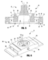
- Figures 3-5 illustrate an example of the first coupling component 28.
- the first coupling component 28 is realized as an adapter for attaching the air dryer body 22.
- the adapter 28 may be generally cylindrical having a bottom portion 40 and a top portion 42 centered on an axis 44 (see Figure 5).
- the bottom portion 40 may include an outer lip 46 and an inner lip 48 connected by a groove 50 for receiving a sealing element 52 (see Figure 2), such as for example, an o -ring.
- the bottom portion 40 may also include a first recessed area 54 and a second recessed area 56.
- the first recessed area 54 being radially outward of the second recessed area 56.
- the second recessed area 56 may include female threads 60 along an inner surface for threadably engaging the threaded extension 32 of the air dryer body 22 (Fig. 2).
- the top portion 42 of the adapter 28 may include an outer lip 62 and an inner lip 64 separated by a groove 66 for receiving a sealing member 52, such as for example an o-ring.
- the top portion 42 may also include a third recessed portion 68 radially separating the inner lip 64 from an axially extending center portion 70.
- the axially extending center portion 70 may include a generally cylindrical axially extending s ide surface 72.
- the side surface 72 may include a radially extending groove 74 for receiving a seal member 52 (Fig. 2).
- the top portion 42 may also include an axially extending stem 76 connected to the side surface 72 by a radially extending surface 78 .
- the stem 76 may include male threads 80 and a radial shoulder 82.
- the adapter 28 may also include one or more flow passages for communicating air through the arrangement 20.
- the adapter 28 may include a first and second pair 84, 86 of flow passages.
- the first pair of flow passages 84 may extend from the first recessed area 54 through the adapter 28 to the third recessed area 68.
- the first pair of flow passages 84 may, though not necessarily, be circumferentially spaced about 180 degrees apart, each passage a substantially equal distance radially from the axis 44.
- the second pair of flow passages 86 may extend from the second recessed area 56 through the adapter 28 to the radially extending surface 78 of the axially extending center portion 70.
- the second pair of flow passages 86 may, but not necessarily, be circumferentially spaced 180 degrees apart, each passage a substantially equal distance radially from the axis 44.
- FIGS. 6-8 illustrate an example of the second coupling component 30.
- the second coupling component 30 is realized as a manifold for attaching to the adapter 28 and for mounting the plurality of desiccant containing canisters 26.
- the manifold 30 may include a bottom portion 90, a top portion 92, and two generally parallel side surfaces 94.
- the manifold 30 may include a bore 96 extending from the bottom portion 90 to the top portion 92 and centered on an axis 98.
- the bottom portion 90 may include a first radially extending, generally planar surface 100 connected to a second radially extending, generally planar surface 102 by a first axially extending surface 104.
- the second radially extending, generally planar surface 102 may be connected to a third radially extending, gene rally planar surface 108 by a second axially extending surface 110.
- the bottom portion 90 may also include a first and second counter bore 112, 114 circumscribing the bore 96.
- the top portion 92 of the manifold 30 may include a generally planar surface 1 16 and two or more extensions 118, each configured to receive one of the desiccant - containing canisters 26. In the illustrated embodiment, a pair of threaded extensions 118a, 118b is provided.
- the top portion 92 may also include a counterbore 120 that circumscribes the bore 96.
- the manifold 30 may also include one or more flow passages for communicating air through the arrangement 20.
- a first flow passage 122 and a second flow passage 124 extend from the first and second threaded extensions 118a, 118b, respectively, through the manifold 30 to the second counter bore 114.
- a third flow passage 126 and a fourth flow passage 128 may extend from the generally planar surface 116, adjacent each extension 118a, 118b, respectively, through the manifold 30 to the first counter bore 112.
- the third and fourth flow passages 126, 128 meet to form a fifth flow passage 130 that extends to the first counter bore 112.
- a purge air flow path 132 also extends through the manifold 30 from a side surface 94 to the second counterbore 114.
- the female threads 60 on the adapter 28 may threadably mount to the extension 32 on the air dryer body 22.
- the adaptor 28 may be threaded onto the manifold extension 32 such that the outer lip 46 and the inner lip 48 engage a surface on the air dryer body 22 and the sealing element 52 in the groove 50 creates a fluid seal between the adapter 28 and the body 22.
- the manifold 30 may assemble onto the adapter 28, such that the stem 76 is received through the bore 96.
- the first radially extending surface 100 on the bottom portion 90 of the manifold 30 may engage the outer and inner lips 62, 64 of the top portion 42 of the adapter 28 such that th e manifold 30 rests on the adapter top portion 42.
- a fastener 128, such as a nut for example, may threadably engage the stem 76 to secure the adapter 28 and the manifold 30 together.
- Sealing elements 52 in the axially extending groove 66, in the radially extending groove 74, and on the shoulder 82 create fluid seals between the adapter 28 and the manifold 30.
- the desiccant containing canisters 26 may mount to the manifold 30, one each on each of the extensions 118a, 118b.
- the second counter bore 114 of the manifold 30 and the radially extending surface 78 of the adapter 28 define an inner chamber 131 (see Figure 2).
- compressed air from a source of compressed air may flow from the body 22, through the adapter 28 via flow passages 84, through the manifold 30 via flow passages 130, 128, and 126, and into each of the desiccant containing canisters 26 in parallel.
- the fifth flow passage 130 may split into the third and fourth flow passages 126, 128 at a location that is substantially an equal distance from each of the desiccant canisters 26. Therefore, a substantially equal amount of compressed air flows to each of the canisters.
- the purge air reservoirs 16 may supply the purge air to the canisters 26 to regenerate the canisters 26 and may receive dried air from the canisters to replenish the purge reservoirs.
- a first purge air reservoir may be in fluid communication with the air dryer body 22 such that air to flow between the body and the first purge reservoir.
- a second purge air reservoir 16 may be in fluid communication with the manifold 30 such that air may flow between the second purge air reservoir 16 and the manifold via the purge flow passage 126.
- purge air flows through the arrangement 2 0 in the reverse direction from the drying phase.
- the purge air reservoirs 16 may connect to the arrangement 20 to supply the purge air.
- a first purge air reservoir may be in fluid communication with the air dry er body 22 such that purge air may flow through the body and enter the coupling device 24 via the flow passage 34.
- a second purge air reservoir may also be in fluid communication with the manifold 30 such that purge air may flow into the coup ling device 24 via the purge flow passage 132. Both the purge air entering the coupling device 24 via the flow passage 34 and via the flow passage 132, flow into the inner chamber 131. In this sense, the inner chamber 131 acts as a mixing chamber for the purge air from the two purge air reservoir.
- the purge air in the inner chamber 131 splits and flows into each of the two desiccant canisters 26 is substantially equal amounts via flow passages 122, 124.
- the inner chamber 131 is configured as a mea ns for balancing the flow of purge air from the plurality of purge air sources to each of the desiccant containing canisters 26.
- the inner chamber 131 is substantially an equal distance from each of the desiccant containing can isters 26.
Landscapes
- Chemical & Material Sciences (AREA)
- Engineering & Computer Science (AREA)
- Analytical Chemistry (AREA)
- General Chemical & Material Sciences (AREA)
- Oil, Petroleum & Natural Gas (AREA)
- Chemical Kinetics & Catalysis (AREA)
- Transportation (AREA)
- Mechanical Engineering (AREA)
- Valves And Accessory Devices For Braking Systems (AREA)
- Drying Of Gases (AREA)
- Air-Conditioning For Vehicles (AREA)
Applications Claiming Priority (1)
| Application Number | Priority Date | Filing Date | Title |
|---|---|---|---|
| US11/595,710 US7981194B2 (en) | 2006-11-10 | 2006-11-10 | Air drying arrangement |
Publications (3)
| Publication Number | Publication Date |
|---|---|
| EP1920984A2 true EP1920984A2 (de) | 2008-05-14 |
| EP1920984A3 EP1920984A3 (de) | 2011-03-23 |
| EP1920984B1 EP1920984B1 (de) | 2018-04-25 |
Family
ID=39133019
Family Applications (1)
| Application Number | Title | Priority Date | Filing Date |
|---|---|---|---|
| EP07120286.5A Not-in-force EP1920984B1 (de) | 2006-11-10 | 2007-11-08 | Lufttrocknungsvorrichtung |
Country Status (4)
| Country | Link |
|---|---|
| US (2) | US7981194B2 (de) |
| EP (1) | EP1920984B1 (de) |
| CA (2) | CA2604447C (de) |
| MX (1) | MX2007013794A (de) |
Families Citing this family (7)
| Publication number | Priority date | Publication date | Assignee | Title |
|---|---|---|---|---|
| US8776834B2 (en) * | 2009-09-02 | 2014-07-15 | Rick Kirby | Device for the deflection of the air jet pulse from the air dryer of large truck air brakes |
| US9481482B2 (en) * | 2012-05-30 | 2016-11-01 | Multisorb Technologies, Inc. | Article dispensing |
| US9375679B2 (en) | 2013-08-30 | 2016-06-28 | Haldex Brake Products Corporation | Air dryer assembly with manifold system |
| DE102015013491A1 (de) * | 2015-10-16 | 2017-04-20 | Man Truck & Bus Ag | Vorrichtung zur lösbaren Befestigung einer Trockenmittelpatrone an einem Gehäuseabschnitt einer Druckluftaufbereitungsanlage eines Fahrzeugs |
| DE102015013493A1 (de) * | 2015-10-16 | 2017-04-20 | Man Truck & Bus Ag | Vorrichtung zur lösbaren Befestigung einer Trockenmittelpatrone an einem Gehäuse einer Druckluftaufbereitungsanlage eines Fahrzeugs |
| DE102015013487A1 (de) * | 2015-10-16 | 2017-04-20 | Man Truck & Bus Ag | Trockenmittelpatrone |
| CA3098157A1 (en) * | 2019-06-28 | 2020-12-28 | Milton Industries, Inc. | Brake de-icing agent insertion apparatus for an air line of a vehicle |
Citations (1)
| Publication number | Priority date | Publication date | Assignee | Title |
|---|---|---|---|---|
| EP0933118A1 (de) | 1998-02-02 | 1999-08-04 | Westinghouse Air Brake Company | Doppelturmlufttrockner |
Family Cites Families (10)
| Publication number | Priority date | Publication date | Assignee | Title |
|---|---|---|---|---|
| US5209764A (en) * | 1991-08-20 | 1993-05-11 | Allied Signal Inc. | Compressed air system with twin air dryers |
| US5378266A (en) * | 1993-08-02 | 1995-01-03 | Alliedsignal Inc. | Air dryer system |
| DE4429822C2 (de) * | 1994-08-23 | 1998-02-19 | Mann & Hummel Filter | Vorrichtung zum Abscheiden von Ölaerosol aus Luft |
| US5662727A (en) * | 1996-02-06 | 1997-09-02 | Westinghouse Air Brake Company | Twin tower air dryer for an air compressor unit |
| US6126724A (en) * | 1999-02-19 | 2000-10-03 | Hansen Inc. | Locomotive air processing apparatus |
| US6125553A (en) * | 1999-05-13 | 2000-10-03 | Alliedsignal Truth Brake Systems Company | Controller module for continuous flow twin air dryers and process of controlling same |
| US6581297B1 (en) | 2000-11-17 | 2003-06-24 | Graham-White Manufacturing Company | Drying apparatus and method |
| US6695893B2 (en) * | 2002-03-29 | 2004-02-24 | Bendix Commercial Vehicle Systems Llc | Continuous flow dryer reservoir module dryer system |
| US6743277B2 (en) * | 2002-05-16 | 2004-06-01 | Bendix Commercial Vehicle Systems Llc | Service reservoir purge of air dryers in pump-off mode |
| US7097696B2 (en) * | 2004-02-27 | 2006-08-29 | Skf Usa Inc. | Dual cartridge air dryer with oil separator and readily changeable valves |
-
2006
- 2006-11-10 US US11/595,710 patent/US7981194B2/en active Active
-
2007
- 2007-09-26 CA CA2604447A patent/CA2604447C/en not_active Expired - Fee Related
- 2007-09-26 CA CA2891230A patent/CA2891230C/en not_active Expired - Fee Related
- 2007-11-05 MX MX2007013794A patent/MX2007013794A/es active IP Right Grant
- 2007-11-08 EP EP07120286.5A patent/EP1920984B1/de not_active Not-in-force
-
2011
- 2011-06-23 US US13/167,232 patent/US8118911B2/en active Active
Patent Citations (1)
| Publication number | Priority date | Publication date | Assignee | Title |
|---|---|---|---|---|
| EP0933118A1 (de) | 1998-02-02 | 1999-08-04 | Westinghouse Air Brake Company | Doppelturmlufttrockner |
Also Published As
| Publication number | Publication date |
|---|---|
| US20110252966A1 (en) | 2011-10-20 |
| CA2604447C (en) | 2015-08-11 |
| CA2891230A1 (en) | 2008-05-10 |
| US7981194B2 (en) | 2011-07-19 |
| MX2007013794A (es) | 2009-02-13 |
| US20080110340A1 (en) | 2008-05-15 |
| EP1920984B1 (de) | 2018-04-25 |
| EP1920984A3 (de) | 2011-03-23 |
| CA2891230C (en) | 2016-12-13 |
| US8118911B2 (en) | 2012-02-21 |
| CA2604447A1 (en) | 2008-05-10 |
Similar Documents
| Publication | Publication Date | Title |
|---|---|---|
| EP1920984A2 (de) | Lufttrocknungsvorrichtung | |
| US8852327B1 (en) | Air dryer cartridge with integrated check valve | |
| US7892329B2 (en) | Air dryer cartridge | |
| EP3038872B1 (de) | Lufttrockneranordnung mit verteilersystem | |
| US20180236398A1 (en) | Air dryer cartridge, air dryer and commercial vehicle comprising an air dryer cartridge | |
| US6878194B2 (en) | Remote purge drying unit for compressed gas | |
| US8500885B2 (en) | Air drier for air suspension of vehicle | |
| US20250346083A1 (en) | Pneumatic control system for vehicle tire inflation | |
| US7100305B2 (en) | Air dryer mounting assembly | |
| US20070028777A1 (en) | Purge valve | |
| US20090025385A1 (en) | Master cylinder | |
| CN108568194A (zh) | 流优化的干燥剂筒 | |
| US20250269308A1 (en) | Air dryer cartridge, oil filter, kit, air dryer, and method of assembling an air dryer | |
| CN116829243B (zh) | 密封接口、空气干燥器筒和空气处理装置 | |
| EP4620557A1 (de) | Lufttrocknerpatrone, formteil für einen lufttrockner, lufttrockner, fahrzeug und verfahren zur herstellung einer lufttrocknerpatrone | |
| CN220785731U (zh) | 储气筒和具有其的车辆 | |
| US20240050887A1 (en) | Air Dryer Device and Air Treatment Device | |
| US20250281874A1 (en) | Air dryer cartridge, air dryer, vehicular air treatment system and vehicle | |
| CN115371307A (zh) | 一种气液分离器 | |
| CN116829243A (zh) | 密封接口、空气干燥器筒和空气处理装置 |
Legal Events
| Date | Code | Title | Description |
|---|---|---|---|
| PUAI | Public reference made under article 153(3) epc to a published international application that has entered the european phase |
Free format text: ORIGINAL CODE: 0009012 |
|
| AK | Designated contracting states |
Kind code of ref document: A2 Designated state(s): AT BE BG CH CY CZ DE DK EE ES FI FR GB GR HU IE IS IT LI LT LU LV MC MT NL PL PT RO SE SI SK TR |
|
| AX | Request for extension of the european patent |
Extension state: AL BA HR MK RS |
|
| PUAL | Search report despatched |
Free format text: ORIGINAL CODE: 0009013 |
|
| AK | Designated contracting states |
Kind code of ref document: A3 Designated state(s): AT BE BG CH CY CZ DE DK EE ES FI FR GB GR HU IE IS IT LI LT LU LV MC MT NL PL PT RO SE SI SK TR |
|
| AX | Request for extension of the european patent |
Extension state: AL BA HR MK RS |
|
| 17P | Request for examination filed |
Effective date: 20110919 |
|
| AKX | Designation fees paid |
Designated state(s): AT BE BG CH CY CZ DE DK EE ES FI FR GB GR HU IE IS IT LI LT LU LV MC MT NL PL PT RO SE SI SK TR |
|
| 17Q | First examination report despatched |
Effective date: 20170209 |
|
| GRAP | Despatch of communication of intention to grant a patent |
Free format text: ORIGINAL CODE: EPIDOSNIGR1 |
|
| INTG | Intention to grant announced |
Effective date: 20171219 |
|
| GRAA | (expected) grant |
Free format text: ORIGINAL CODE: 0009210 |
|
| GRAS | Grant fee paid |
Free format text: ORIGINAL CODE: EPIDOSNIGR3 |
|
| AK | Designated contracting states |
Kind code of ref document: B1 Designated state(s): AT BE BG CH CY CZ DE DK EE ES FI FR GB GR HU IE IS IT LI LT LU LV MC MT NL PL PT RO SE SI SK TR |
|
| REG | Reference to a national code |
Ref country code: GB Ref legal event code: FG4D |
|
| REG | Reference to a national code |
Ref country code: CH Ref legal event code: EP |
|
| REG | Reference to a national code |
Ref country code: AT Ref legal event code: REF Ref document number: 992531 Country of ref document: AT Kind code of ref document: T Effective date: 20180515 |
|
| REG | Reference to a national code |
Ref country code: IE Ref legal event code: FG4D |
|
| REG | Reference to a national code |
Ref country code: DE Ref legal event code: R096 Ref document number: 602007054654 Country of ref document: DE |
|
| REG | Reference to a national code |
Ref country code: NL Ref legal event code: FP |
|
| REG | Reference to a national code |
Ref country code: SE Ref legal event code: TRGR |
|
| REG | Reference to a national code |
Ref country code: LT Ref legal event code: MG4D |
|
| PG25 | Lapsed in a contracting state [announced via postgrant information from national office to epo] |
Ref country code: FI Free format text: LAPSE BECAUSE OF FAILURE TO SUBMIT A TRANSLATION OF THE DESCRIPTION OR TO PAY THE FEE WITHIN THE PRESCRIBED TIME-LIMIT Effective date: 20180425 Ref country code: BG Free format text: LAPSE BECAUSE OF FAILURE TO SUBMIT A TRANSLATION OF THE DESCRIPTION OR TO PAY THE FEE WITHIN THE PRESCRIBED TIME-LIMIT Effective date: 20180725 Ref country code: PL Free format text: LAPSE BECAUSE OF FAILURE TO SUBMIT A TRANSLATION OF THE DESCRIPTION OR TO PAY THE FEE WITHIN THE PRESCRIBED TIME-LIMIT Effective date: 20180425 Ref country code: ES Free format text: LAPSE BECAUSE OF FAILURE TO SUBMIT A TRANSLATION OF THE DESCRIPTION OR TO PAY THE FEE WITHIN THE PRESCRIBED TIME-LIMIT Effective date: 20180425 Ref country code: LT Free format text: LAPSE BECAUSE OF FAILURE TO SUBMIT A TRANSLATION OF THE DESCRIPTION OR TO PAY THE FEE WITHIN THE PRESCRIBED TIME-LIMIT Effective date: 20180425 |
|
| PG25 | Lapsed in a contracting state [announced via postgrant information from national office to epo] |
Ref country code: GR Free format text: LAPSE BECAUSE OF FAILURE TO SUBMIT A TRANSLATION OF THE DESCRIPTION OR TO PAY THE FEE WITHIN THE PRESCRIBED TIME-LIMIT Effective date: 20180726 Ref country code: LV Free format text: LAPSE BECAUSE OF FAILURE TO SUBMIT A TRANSLATION OF THE DESCRIPTION OR TO PAY THE FEE WITHIN THE PRESCRIBED TIME-LIMIT Effective date: 20180425 |
|
| REG | Reference to a national code |
Ref country code: AT Ref legal event code: MK05 Ref document number: 992531 Country of ref document: AT Kind code of ref document: T Effective date: 20180425 |
|
| PG25 | Lapsed in a contracting state [announced via postgrant information from national office to epo] |
Ref country code: PT Free format text: LAPSE BECAUSE OF FAILURE TO SUBMIT A TRANSLATION OF THE DESCRIPTION OR TO PAY THE FEE WITHIN THE PRESCRIBED TIME-LIMIT Effective date: 20180827 |
|
| REG | Reference to a national code |
Ref country code: DE Ref legal event code: R097 Ref document number: 602007054654 Country of ref document: DE |
|
| PG25 | Lapsed in a contracting state [announced via postgrant information from national office to epo] |
Ref country code: RO Free format text: LAPSE BECAUSE OF FAILURE TO SUBMIT A TRANSLATION OF THE DESCRIPTION OR TO PAY THE FEE WITHIN THE PRESCRIBED TIME-LIMIT Effective date: 20180425 Ref country code: AT Free format text: LAPSE BECAUSE OF FAILURE TO SUBMIT A TRANSLATION OF THE DESCRIPTION OR TO PAY THE FEE WITHIN THE PRESCRIBED TIME-LIMIT Effective date: 20180425 Ref country code: CZ Free format text: LAPSE BECAUSE OF FAILURE TO SUBMIT A TRANSLATION OF THE DESCRIPTION OR TO PAY THE FEE WITHIN THE PRESCRIBED TIME-LIMIT Effective date: 20180425 Ref country code: EE Free format text: LAPSE BECAUSE OF FAILURE TO SUBMIT A TRANSLATION OF THE DESCRIPTION OR TO PAY THE FEE WITHIN THE PRESCRIBED TIME-LIMIT Effective date: 20180425 Ref country code: DK Free format text: LAPSE BECAUSE OF FAILURE TO SUBMIT A TRANSLATION OF THE DESCRIPTION OR TO PAY THE FEE WITHIN THE PRESCRIBED TIME-LIMIT Effective date: 20180425 Ref country code: SK Free format text: LAPSE BECAUSE OF FAILURE TO SUBMIT A TRANSLATION OF THE DESCRIPTION OR TO PAY THE FEE WITHIN THE PRESCRIBED TIME-LIMIT Effective date: 20180425 |
|
| PLBE | No opposition filed within time limit |
Free format text: ORIGINAL CODE: 0009261 |
|
| STAA | Information on the status of an ep patent application or granted ep patent |
Free format text: STATUS: NO OPPOSITION FILED WITHIN TIME LIMIT |
|
| 26N | No opposition filed |
Effective date: 20190128 |
|
| PG25 | Lapsed in a contracting state [announced via postgrant information from national office to epo] |
Ref country code: SI Free format text: LAPSE BECAUSE OF FAILURE TO SUBMIT A TRANSLATION OF THE DESCRIPTION OR TO PAY THE FEE WITHIN THE PRESCRIBED TIME-LIMIT Effective date: 20180425 |
|
| REG | Reference to a national code |
Ref country code: CH Ref legal event code: PL |
|
| PG25 | Lapsed in a contracting state [announced via postgrant information from national office to epo] |
Ref country code: LU Free format text: LAPSE BECAUSE OF NON-PAYMENT OF DUE FEES Effective date: 20181108 Ref country code: MC Free format text: LAPSE BECAUSE OF FAILURE TO SUBMIT A TRANSLATION OF THE DESCRIPTION OR TO PAY THE FEE WITHIN THE PRESCRIBED TIME-LIMIT Effective date: 20180425 |
|
| REG | Reference to a national code |
Ref country code: BE Ref legal event code: MM Effective date: 20181130 |
|
| REG | Reference to a national code |
Ref country code: IE Ref legal event code: MM4A |
|
| PG25 | Lapsed in a contracting state [announced via postgrant information from national office to epo] |
Ref country code: LI Free format text: LAPSE BECAUSE OF NON-PAYMENT OF DUE FEES Effective date: 20181130 Ref country code: CH Free format text: LAPSE BECAUSE OF NON-PAYMENT OF DUE FEES Effective date: 20181130 |
|
| PG25 | Lapsed in a contracting state [announced via postgrant information from national office to epo] |
Ref country code: IE Free format text: LAPSE BECAUSE OF NON-PAYMENT OF DUE FEES Effective date: 20181108 |
|
| PG25 | Lapsed in a contracting state [announced via postgrant information from national office to epo] |
Ref country code: BE Free format text: LAPSE BECAUSE OF NON-PAYMENT OF DUE FEES Effective date: 20181130 |
|
| PG25 | Lapsed in a contracting state [announced via postgrant information from national office to epo] |
Ref country code: MT Free format text: LAPSE BECAUSE OF NON-PAYMENT OF DUE FEES Effective date: 20181108 |
|
| PGFP | Annual fee paid to national office [announced via postgrant information from national office to epo] |
Ref country code: DE Payment date: 20191121 Year of fee payment: 13 Ref country code: SE Payment date: 20191121 Year of fee payment: 13 Ref country code: NL Payment date: 20191120 Year of fee payment: 13 |
|
| PGFP | Annual fee paid to national office [announced via postgrant information from national office to epo] |
Ref country code: FR Payment date: 20191120 Year of fee payment: 13 Ref country code: IT Payment date: 20191128 Year of fee payment: 13 |
|
| PG25 | Lapsed in a contracting state [announced via postgrant information from national office to epo] |
Ref country code: TR Free format text: LAPSE BECAUSE OF FAILURE TO SUBMIT A TRANSLATION OF THE DESCRIPTION OR TO PAY THE FEE WITHIN THE PRESCRIBED TIME-LIMIT Effective date: 20180425 |
|
| PGFP | Annual fee paid to national office [announced via postgrant information from national office to epo] |
Ref country code: GB Payment date: 20191120 Year of fee payment: 13 |
|
| PG25 | Lapsed in a contracting state [announced via postgrant information from national office to epo] |
Ref country code: CY Free format text: LAPSE BECAUSE OF FAILURE TO SUBMIT A TRANSLATION OF THE DESCRIPTION OR TO PAY THE FEE WITHIN THE PRESCRIBED TIME-LIMIT Effective date: 20180425 Ref country code: HU Free format text: LAPSE BECAUSE OF FAILURE TO SUBMIT A TRANSLATION OF THE DESCRIPTION OR TO PAY THE FEE WITHIN THE PRESCRIBED TIME-LIMIT; INVALID AB INITIO Effective date: 20071108 |
|
| PG25 | Lapsed in a contracting state [announced via postgrant information from national office to epo] |
Ref country code: IS Free format text: LAPSE BECAUSE OF FAILURE TO SUBMIT A TRANSLATION OF THE DESCRIPTION OR TO PAY THE FEE WITHIN THE PRESCRIBED TIME-LIMIT Effective date: 20180825 |
|
| REG | Reference to a national code |
Ref country code: DE Ref legal event code: R119 Ref document number: 602007054654 Country of ref document: DE |
|
| REG | Reference to a national code |
Ref country code: SE Ref legal event code: EUG |
|
| REG | Reference to a national code |
Ref country code: NL Ref legal event code: MM Effective date: 20201201 |
|
| GBPC | Gb: european patent ceased through non-payment of renewal fee |
Effective date: 20201108 |
|
| PG25 | Lapsed in a contracting state [announced via postgrant information from national office to epo] |
Ref country code: SE Free format text: LAPSE BECAUSE OF NON-PAYMENT OF DUE FEES Effective date: 20201109 Ref country code: NL Free format text: LAPSE BECAUSE OF NON-PAYMENT OF DUE FEES Effective date: 20201201 |
|
| PG25 | Lapsed in a contracting state [announced via postgrant information from national office to epo] |
Ref country code: IT Free format text: LAPSE BECAUSE OF NON-PAYMENT OF DUE FEES Effective date: 20201108 Ref country code: FR Free format text: LAPSE BECAUSE OF NON-PAYMENT OF DUE FEES Effective date: 20201130 |
|
| PG25 | Lapsed in a contracting state [announced via postgrant information from national office to epo] |
Ref country code: DE Free format text: LAPSE BECAUSE OF NON-PAYMENT OF DUE FEES Effective date: 20210601 Ref country code: GB Free format text: LAPSE BECAUSE OF NON-PAYMENT OF DUE FEES Effective date: 20201108 |