EP1920992A1 - Elektrische servolenkvorrichtung - Google Patents
Elektrische servolenkvorrichtung Download PDFInfo
- Publication number
- EP1920992A1 EP1920992A1 EP06797320A EP06797320A EP1920992A1 EP 1920992 A1 EP1920992 A1 EP 1920992A1 EP 06797320 A EP06797320 A EP 06797320A EP 06797320 A EP06797320 A EP 06797320A EP 1920992 A1 EP1920992 A1 EP 1920992A1
- Authority
- EP
- European Patent Office
- Prior art keywords
- motor
- bus bars
- fixing base
- electric motor
- power steering
- Prior art date
- Legal status (The legal status is an assumption and is not a legal conclusion. Google has not performed a legal analysis and makes no representation as to the accuracy of the status listed.)
- Withdrawn
Links
- 238000003780 insertion Methods 0.000 claims description 21
- 230000037431 insertion Effects 0.000 claims description 21
- 206010070245 Foreign body Diseases 0.000 description 10
- 230000005855 radiation Effects 0.000 description 7
- 239000011347 resin Substances 0.000 description 6
- 229920005989 resin Polymers 0.000 description 6
- 239000000428 dust Substances 0.000 description 5
- 230000007246 mechanism Effects 0.000 description 5
- 230000006870 function Effects 0.000 description 4
- 238000004519 manufacturing process Methods 0.000 description 4
- 238000005516 engineering process Methods 0.000 description 3
- 239000002184 metal Substances 0.000 description 3
- 230000000694 effects Effects 0.000 description 2
- 230000002708 enhancing effect Effects 0.000 description 2
- 238000009434 installation Methods 0.000 description 2
- 238000005192 partition Methods 0.000 description 2
- 239000011248 coating agent Substances 0.000 description 1
- 238000000576 coating method Methods 0.000 description 1
- 239000012141 concentrate Substances 0.000 description 1
- 239000004020 conductor Substances 0.000 description 1
- 230000006378 damage Effects 0.000 description 1
- 239000004519 grease Substances 0.000 description 1
- 230000006872 improvement Effects 0.000 description 1
- 239000012212 insulator Substances 0.000 description 1
- 239000000696 magnetic material Substances 0.000 description 1
- 230000004048 modification Effects 0.000 description 1
- 238000012986 modification Methods 0.000 description 1
- 230000007659 motor function Effects 0.000 description 1
- 238000000465 moulding Methods 0.000 description 1
- 239000011295 pitch Substances 0.000 description 1
- 230000009467 reduction Effects 0.000 description 1
- 239000007787 solid Substances 0.000 description 1
- 239000000758 substrate Substances 0.000 description 1
- 238000004804 winding Methods 0.000 description 1
Images


Classifications
-
- B—PERFORMING OPERATIONS; TRANSPORTING
- B62—LAND VEHICLES FOR TRAVELLING OTHERWISE THAN ON RAILS
- B62D—MOTOR VEHICLES; TRAILERS
- B62D5/00—Power-assisted or power-driven steering
- B62D5/04—Power-assisted or power-driven steering electrical, e.g. using an electric servo-motor connected to, or forming part of, the steering gear
- B62D5/0403—Power-assisted or power-driven steering electrical, e.g. using an electric servo-motor connected to, or forming part of, the steering gear characterised by constructional features, e.g. common housing for motor and gear box
- B62D5/0406—Power-assisted or power-driven steering electrical, e.g. using an electric servo-motor connected to, or forming part of, the steering gear characterised by constructional features, e.g. common housing for motor and gear box including housing for electronic control unit
-
- H—ELECTRICITY
- H02—GENERATION; CONVERSION OR DISTRIBUTION OF ELECTRIC POWER
- H02K—DYNAMO-ELECTRIC MACHINES
- H02K11/00—Structural association of dynamo-electric machines with electric components or with devices for shielding, monitoring or protection
- H02K11/30—Structural association with control circuits or drive circuits
- H02K11/33—Drive circuits, e.g. power electronics
-
- H—ELECTRICITY
- H02—GENERATION; CONVERSION OR DISTRIBUTION OF ELECTRIC POWER
- H02K—DYNAMO-ELECTRIC MACHINES
- H02K5/00—Casings; Enclosures; Supports
- H02K5/04—Casings or enclosures characterised by the shape, form or construction thereof
- H02K5/22—Auxiliary parts of casings not covered by groups H02K5/06-H02K5/20, e.g. shaped to form connection boxes or terminal boxes
- H02K5/225—Terminal boxes or connection arrangements
-
- H—ELECTRICITY
- H02—GENERATION; CONVERSION OR DISTRIBUTION OF ELECTRIC POWER
- H02K—DYNAMO-ELECTRIC MACHINES
- H02K7/00—Arrangements for handling mechanical energy structurally associated with dynamo-electric machines, e.g. structural association with mechanical driving motors or auxiliary dynamo-electric machines
- H02K7/10—Structural association with clutches, brakes, gears, pulleys or mechanical starters
- H02K7/116—Structural association with clutches, brakes, gears, pulleys or mechanical starters with gears
Definitions
- the present invention relates to an electric power steering apparatus using an electric motor as a source for generating steering assisting torque and, more specifically, the invention relates to an electric power steering apparatus which is improved not only in a mounting structure for an electric motor and a control unit (ECU) disposed adjacent to the electric motor for controlling the drive of the electric motor, but also in a connecting structure for connecting together an electric motor for applying steering assisting torque to the steering system of a vehicle and a controller for controlling the drive of the electric motor.
- ECU control unit
- an electric motor is driven according to steering torque applied thereto through steering wheels, and the rotation of the electric motor is transmitted through a reduction mechanism to a steering mechanism to thereby assist the steering of the vehicle.
- This electric motor for steering assistance is electrically connected to an ECU including a motor drive circuit and the like, and can be driven and controlled by the ECU.
- This electric power steering apparatus generally, includes a torque sensor for detecting steering torque applied to rotating steering wheels, an electric motor for assisting the operation of a driver, and a controller for controlling the drive of the electric motor, in which the electric motor is driven according to the steering torque detected by the torque sensor.
- the rotation output of the electric motor functions as steering assisting torque, and this rotation output is transmitted to the output shaft of a steering mechanism while it is reduced by a gear mechanism. Owing to this, while a steering power applied to the steering wheels is being assisted, the steering of the vehicle is carried out.
- a connecting structure in which an electric motor (a brushless motor) and an ECU (a casing) are disposed adjacent to each other; and, Fig. 5 is an explanatory view of this connecting structure.
- a brushless motor 101 and a casing 102 are connected together by three bus bars; and, the three bus bars are respectively structured such that bus bars 103a - 103c projected from the interior of the brushless motor 101 and bus bars 104a - 104c projected from the interior of the casing 102 are connected together by switches 105a - 105c respectively shown in Fig. 5(b) .
- the bus bars 103a - 103c are respectively made of magnetic material and, to the sides of the bus bars 104a - 104c that do not face the bus bars 103a - 103c, there are fixed electromagnets 107a -107c through an insulating member 106.
- the bus bars 103a - 103c arranged on the brushless motor 101 side are attracted to the bus bars 104a - 104c arranged on the casing 102 side, so that these bus bars are connected together.
- Patent Reference 1 JP-A-2005-206084
- the harness is sometimes hard to mount.
- the required degree of the performance of the electric power steering apparatus to be carried on the vehicle has been increasing year after year and, especially, the electric power steering apparatus has been required that it can enhance the rotating steering performance and heat radiating performance as well as it can reduce radio noises.
- a connector highly resistant to the radio noises is used, the cost of the structure is high.
- Patent Reference 2 JP-A-2003-267233
- the present invention aims at solving the above problems found in the conventional connecting structures.
- ECU control unit
- the conventional technology there is employed a structure for unifying an electric motor and a controller into an integral body. Specifically, when connecting together the electric motor and controller, there is employed a structure in which the bus bars are projected externally from a power substrate stored within the housing of the controller, and these bus bars are inserted into the housing of the electric motor and are screwed within the housing of the electric motor. Therefore, after mounted on a gear box, the ECU is difficult to mount and remove as a single part, which is not sufficient to enhance the efficiency of an assembling operation. Further, in the conventional technology, the bus bar insertion opening on the electric motor side is open and thus, when delivery or transporting the electric motor as a single part, it is necessary to separately provide means for preventing dust and the like from entering the bus bar insertion opening.
- the present invention is made to solve the above problems found in the conventional technology.
- it is an object of the invention to enhance the assembling efficiency of an electric power steering apparatus when the electric motor and controller thereof are connected together.
- an electric power steering apparatus including an electric motor to be connected to a control unit through bus bars respectively projected from the inside of the electric motor, the control unit controlling drive of the electric motor to assist a steering of a vehicle, wherein the control unit is fixed to a fixing base made as a composing element of the electric motor, and the fixing base covers the connecting portion between the bus bars and the control unit.
- the above object is attained effectively by the electric power steering apparatus wherein the fixing base in such a manner that the fixing base shields electromagnetic waves generated in the connecting portion between the bus bars and the control unit.
- the fixing base includes a bus bar recessed portion in which the bus bars projected from the inside of the electric motor is disposed, and the opening of the bus bar recessed portion is closed by the control unit to be fixed to the fixing base.
- the bus bar recessed portion includes in the bottom surface thereof bolt insertion holes into which bolts for connecting the bus bars to connecting terminals of the control unit are inserted, and the bolt insertion holes are closed by a seal member after the bolts are respectively inserted into the bolt insertion holes to connect together the bus bars and the connecting terminals respectively.
- the above object can be accomplished more effectively by an electric power steering apparatus in which the inside of the above bus bar recessed portion is insulated by a non-conductive member.
- an electric power steering apparatus including: an electric motor for applying steering assisting torque to a steering system of a vehicle; a controller for controlling drive of the electric motor; and a fixing base as a composing element of the electric motor for fixing the electric motor and the controller thereto, wherein the fixing base includes two or more motor bus bars for transmitting a motor drive current to the respective motor coils of the electric motor, the connecting terminal portions of the respective motor bus bars are projected from the fixing base, the respective motor coils of the electric motor fixed to the fixing base are connected to the motor bus bars, and the respective power line bus bars of the controller fixed to the fixing base for transmitting the drive current are electrically connected to the connecting terminal portions of the motor bus bars.
- the controller and electric motor can be electrically connected to each other without using a harness. Therefore, after the controller and electric motor are assembled to a gear box, without removing the electric motor, the controller can be replaced easily as a single part, thereby being able to contributing toward enhancing the assembling efficiency of the electric motor and controller.
- screw insertion slotted holes are respectively formed in such a manner that the longitudinal directions thereof intersect with each other. This makes it possible not only to absorb an installation error occurring when the power line bus bars are respectively connected to the connecting terminal portions of the motor bus bars by screws, but also to ease stresses produced in the mounting operation.
- each of the motor bus bars includes a bent portion formed in the portion thereof projected from the fixing base, even when a force caused by vibrations is applied to the leading end side of each bus bar, the bent portion is deformed according to such vibrations to thereby be able to prevent stresses from concentrating on the base end side of each bus bar.
- the motor bus bars except for the connecting terminal portions thereof are covered with an insulating member, and also since an insulating member is interposed between the respective motor bus bars, it is possible to prevent the bus bars from touching each other and prevent the bus bars from touching the conductive member, thereby being able to prevent the occurrence of short-circuiting.
- the connecting terminal portions of the motor bus bars are covered with a conductive member and a protect cover for covering the surface of the conductive member, and the conductive member of the protect cover is electrically connected to the casing of the controller.
- This structure can cut off noises coming from the outside and can cut off the radiation of noises to the outside, thereby being able to enhance the shield performance of the present electric power steering apparatus. Also, it is possible not only to prevent the occurrence of short-circuiting that could be otherwise caused by contact between other parts and the respective bus bars and terminals, but also to prevent a foreign object such as dust from sticking to the respective motor bus bars and the like.
- the electric motor and controller are mounted on a gear box under the condition that the electric motor and the controller have been fixed to the fixing base, there can be carried out an operation to assemble together the electric motor and controller before they are mounted onto the gear box. This can contribute toward enhancing the efficiency of the assembling operation.
- the fixing base which is structured as a composing element of the electric motor, can be used not only to fix the control unit (ECU) but also to cover the connecting portion between the bus bars and control unit.
- This structure not only can prevent electromagnetic noises generated in the connecting portion from having ill influences on electric parts provided outside the connecting portion but also can prevent a foreign object from touching the connecting portion to thereby cause short-circuiting.
- the number of parts and the number of assembling steps can be reduced, thereby being able to reduce the manufacturing cost of the electric power steering apparatus.
- the space of the electric power steering apparatus can be saved, the freedom of the mounting layout of the electric power steering apparatus onto a vehicle can be enhanced.
- the fixing base includes a bus bar recessed portion and the opening of the bus bar recessed portion is closed by a control unit which is fixed to the fixing base, electromagnetic waves can be shielded easily without increasing the number of parts and the number of assembling steps.
- the bolt insertion holes are closed by the seal member. This can shield the electromagnetic waves more positively.
- the power line is electrically connected without using a harness or a connector, there can be provided the following effects: that is, the output performance of the electric power steering apparatus can be enhanced and the manufacturing cost thereof can be reduced; radiation noises can be reduced; the anti-noise performance and assembling efficiency of the electric power steering apparatus can be enhanced; the efficiency of an operation to mount and remove the controller as a single part after it is mounted on the gear box can be enhanced; and, the heat radiation performance of the electric power steering apparatus can be enhanced. Also, an improvement over the patent reference 1 is that the efficiency of the operation to mount and remove the controller as a single part after it is mounted on the gear box is enhanced.
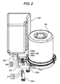
- FIG. 1 is a perspective view of a mounting structure for mounting the electric motor and control unit (ECU) of an electric power steering apparatus according to an embodiment of the invention.
- an electric motor 201 for steering assistance includes a fixing base 202 formed by extending a motor flange which is an element of the composing parts of the electric motor 201.
- a control unit (ECU) 203 for controlling the drive of the electric motor 201 through fixing bolts 204a, 204b. That is, according to the present mounting structure, the electric motor 201 and ECU 203 are disposed adjacent to each other.
- the ECU 203 is connected to other electric parts such as a power source and various sensors through harnesses (not shown) to be connected to connectors 205 which are provided in the bottom portion of the ECU 203.
- the fixing base 202 is formed by extending the motor flange; however, this is not limitative but, for example, the fixing base 202 may also be formed by extending a motor case.
- Fig. 2 is an exploded perspective view of the mounting structure shown in Fig. 1 .
- Fig. 3 (a) is a section view of the main portions of a connecting portion between the electric motor 201 and ECU 203 shown in Fig. 1 .
- a bus bar recessed portion 207 in the surface of the fixing base 202 to which the ECU 203 is to be fixed, there is formed a bus bar recessed portion 207 in which there can be provided three bus bars 206 (206a, 206b and 206c) respectively projected from the interior of the electric motor 201.
- the upper surface of the bus bar recessed portion 207 is formed as an opening in order to be able to connect together the electric motor 201 and ECU 203, while this opening can be closed by mounting the ECU 203 onto the fixing base 202.
- the connecting bolt insertion holes 209 which are opened up in the bottom surface of the bus bar recessed portion 207, after the connecting bolts 210 are inserted through the connecting bolt insertion holes 209 to thereby connect together the bus bars 206 and terminal base 211, the connecting bolt insertion holes 209 are closed by a conductive seal member 212 such as seal tape (see Fig. 4 ).
- the bus bars 206 and terminal base 211 which function as the connecting portion between the electric motor 201 and ECU 203, are covered with the fixing base 202, whereby not only the connecting portion is shielded such that electromagnetic waves are prevented from leaking to the outside but also a foreign object is prevented from touching the connecting portion from the outside.
- an insulating member 213 composed of a non-conductive member on the inner surface of the bus bar recessed portion 207. In this case, even when the connecting bolt 210 happens to loosen, it is possible to prevent the connecting bolt 210 and bus bar recessed portion 207 from touching each other to thereby cause grounding.
- the fixing base 202 which is formed by extending a motor flange which is an element of the composing parts of the electric motor 201, includes the bus bar recessed portion 207 in which the bus bars 206 projected from the interior of the electric motor 201 can be disposed, fixes and supports the ECU 203, and covers the bus bars 206 and terminal base 211 which function as the connecting portion between the electric motor 201 and ECU 203.
- This structure not only can shield electromagnetic waves generated in the connecting portion but also can eliminate the need for separate provision of a cover member for preventing a foreign object from touching the connecting portion.
- the present embodiment can reduce the number of parts and the number of assembling steps to thereby be able not only to reduce the manufacturing cost thereof but also to save the space of a vehicle for carrying the electric power steering apparatus and thus enhance the freedom of the carrying layout of the electric power steering apparatus in the vehicle.
- the bolt insertion holes 209 opened in the bottom surface of the bus bar recessed portion 207 of the fixing base 202 are closed by the conductive seal member 212 after the bus bars 206 and the terminal base 211 of the ECU 203 are connected together by the connecting bolts 210.
- the seal member 212 is made of conductive material, more positive electromagnetic wave shielding can be realized.
- the non-conductive insulating member 213 is disposed on the inner surface of the bus bar recessed portion 207, it is possible to prevent the bus bar recessed portion 207 and connecting bolt 210 from touching each other and thus to prevent the occurrence of grounding.
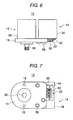
- Fig. 6 is a side view of an electric power steering apparatus according to the present invention
- Fig. 7 is a bottom view of the electric power steering apparatus shown in Fig. 6
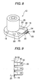
- Fig. 8 is a perspective view of an electric motor and a fixing base
- Fig. 9 is a perspective view of the fixing base and bus bars when they are viewed from above
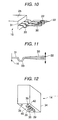
- Fig. 10 is a perspective view of the fixing base and bus bars when they are viewed from laterally
- Fig. 11 is a side view of a bus bar
- Fig. 12 is a perspective view of a controller
- Fig. 6 is a side view of an electric power steering apparatus according to the present invention
- Fig. 7 is a bottom view of the electric power steering apparatus shown in Fig. 6
- Fig. 8 is a perspective view of an electric motor and a fixing base
- Fig. 9 is a perspective view of the fixing base and bus bars when they are viewed from above
- Fig. 10 is a perspective view of the fixing base and bus bars when
- FIG. 13 is a perspective view of a connecting terminal when it is viewed from ahead
- Fig. 14 is an internal structure view of the connecting terminal
- Fig. 15 is an internal structure view of the connecting terminal, showing a state in which nuts are mounted
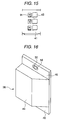
- Fig. 16 is a perspective view of a protect cover.
- an electric power steering (EPS) apparatus 10 includes an electric motor 12, a controller (ECU) 14, and the composing parts of the electric motor 12 such as a fixing base 16 which is formed by extending a motor flange or a motor casing, while the controller 14 is fixed on the fixing base 16 by a screw.
- a fixing base 16 which is a composing part of the electric motor 12
- a groove 24 into which there can be inserted three motor bus bars 22; insulating resin 25 is loaded into the groove 24; and, the motor bus bars 22 are respectively covered with the insulating resin 25 and also they are insulated from each other by the insulating resin 25.
- the electric motor 12 as a motor for applying steering assisting torque to the steering system of a vehicle, is composed of, for example, a three-phase brushless motor; and, an output shaft 28 is rotatably inserted into a main body (motor casing) 26 which is formed in a cylindrical shape and is fixed to the fixing base 16.
- This output shaft 28 is structured such that it can be connected to a steering mechanism (not shown) functioning as a steering system.
- the main body 26 there are stored a rotor (not shown) to which a permanent magnet constituting a magnetic pole is fixed, and a stator (not shown) which is disposed in the periphery of the rotor and is fixed to the main body 26.
- the stator includes, for example, motor coils (armature windings) respectively composed of three phases, namely, U phase, V phase and W phase, while the motor coils are respectively connected to three motor bus bars 22 electrically.
- Each of the three motor bus bars 22 is made of conductive metal, has a rectangular-shaped section, and is arranged in a linear manner.
- Each motor bus bar 22 includes a terminal connecting portion 30 formed on the leading end side thereof and a flat portion 31 formed on the base end side thereof; and, between the terminal connecting portion 30 and flat portion 31, there is formed a bent portion 33 which is bent worked in a horseshoe shape.
- the flat portion 31 of each motor bus bar 22 is disposed within the groove 24, while a portion of the flat portion 31 is projected from the fixing base 16 together with the bent portion 33 and connecting terminal portion 30.
- each bus bar 22 there is formed a slotted hole 32 for insertion.
- the screw hole of the motor bus bar 22 is formed along the longitudinal direction (a direction perpendicular to the motor shaft) of the bus bar in order that, when connecting together the electric motor 12 and controller 14 by a screw, their mounting accuracy errors can be absorbed.
- the controller 14 includes a casing 34 formed in an almost rectangular solid shape.
- a casing 34 formed in an almost rectangular solid shape.
- the insulating connecting terminal 40 includes a terminal hold base 41 formed in a flat plate shape, two or more insulating partition walls 43 respectively formed in the terminal hold base 41, and power line bus bars 45 respectively interposed between the respective insulating partition walls.
- each of the power line bus bars 45 there is formed a screw insertion slotted hole 42 in correspondence to the slotted hole 32 of the motor bus bar 22; and, on the back surface side of each slotted hole 42, there is provided a nut 64.
- Each slotted hole 42 is formed such that the longitudinal direction thereof intersects with the longitudinal direction of the slotted hole 32 of the bus bar 22.
- the motor bus bar 22 and insulating connecting terminal 40 can be connected together positively without applying any stress to the motor bus bar 22 and the power line bus bar 45, the slotted hole 42 of the terminal 45 and the slotted hole 32 of the motor bus bar 22 are formed in such a manner that their respective longitudinal directions intersect with each other.
- a drive circuit (not shown) which receives a signal from a torque sensor (not shown) used to detect a steering power and information expressing the running states of a vehicle such as a steering angle and a vehicle speed and generates a motor drive current, and other elements.
- This drive circuit is allowed to output a motor driving current to the connecting terminal 40 through the power line bus bars (45, 45, and 45) of U phase, V phase and W phase; and, each power line bus bar 45 includes the slotted hole 42 on the side of the surface thereof that is connected to the motor.
- the casing 34 is made of metal, since the insulating connecting terminal 40 is disposed in such a manner that it is projected from the bottom portion of the casing 34, even when the casing 34 is fixed on the fixing base 16 by a screw, it is possible to prevent the casing 34 from touching the respective motor bus bars 22 to thereby cause shorting.
- the protect cover 38 is formed as an integral body of a projecting portion 44 and two flat-plate-shaped fixed portions 46 and 48 respectively disposed on the two sides of the projecting portion 44; and, the projecting portion 44 is formed to have a shape capable of covering the connecting terminal portions 30 of the respective motor bus bars 22.
- the protect cover 38 is made mainly of a conductive member (metal) 52 and, on the front and back surfaces of the conductive member 52, there are coated or molded insulating members (insulator) 54.
- insulator molded insulating members
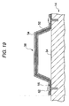
- Fig. 18(a) the main body 26 of the electric motor 12 is placed on the fixing base 16 formed of a composing element of the electric motor 12, the motor bus bars 22 are respectively disposed in the groove 24, and the main body 26 is fixed to the fixing base 16 using a screw.
- the controller 14 is placed onto the fixing base 16 adjacently to the main body 26 of the electric motor 12.
- a screw 58 is inserted into the screw hole 20 of the fixing base 16 and the case 14 is fixed onto the fixing base 16 using the screw 58.
- the motor bus bars 22 are arranged so as to face the connecting terminal 40.
- the main body 26 functioning as a motor casing is connected to the casing 14 through the fixing base 16 and screw 58, whereby common noises generated in the electric motor 12 are fed back to the casing 34 of the controller 14 to thereby be able to control the radiation of the common noises.
- the conductive member 52 of the protect cover 38 can be electrically connected to the casing 34 through the screws 62. This can cut off noises coming from the outside and can cut off the radiation of the noises to the outside, thereby being able to enhance the shield performance. Also, according to this structure, shorting due to contact between the other parts and the respective motor bus bars 22 or terminals can be prevented, and also the sticking of a foreign object such as dust to the respective motor bus bars 22 or the like can be prevented.
- the electric motor 12 and controller 14 when the electric motor 12 and controller 14 are fixed to the fixing base 16, since the connecting terminal portions 30 of the respective motor bus bars 22 respectively projected from the fixing base 16 are connected to their associated power line bus bars within the casing 34 using the screws 60, the electric motor 12 and controller 14 can be electrically connected to each other, thereby being able to enhance the assembling performance of the present embodiment.
- the controller 14 since the controller 14 is fixed on the fixing base 16 that is formed of a composing element of the electric motor 12, the controller 14 can be fixed onto the fixing base 16 before the electric motor 12 and controller 14 are mounted onto the gear box, which can enhance the efficiency of an assembling operation to mount the electric motor 12 and controller 14 onto the gear box.
- the fixing base 16 functions as a heat radiating portion capable of radiating heat generated from the electric motor 12 and controller 14, the heat radiating performance of the present embodiment can be enhanced. Also, when grease is applied onto the contact surfaces of the main body 26 of the electric motor 12 and fixing base 16 as well as onto the contact surfaces of the casing 34 of the controller 14 and fixing base 16, the heat radiating performance of the present embodiment can be enhanced further.
- the electric motor 12 and controller 14 are unified together while they are fixed to the fixing base 16, the electric motor 12 and controller 14 can be electrically connected to each other without using a harness, thereby being able to contributing toward reducing electric noises.
- the fixing base 16 can also made of a different element (a separate element) from the composing element of the electric motor 12.
- the slotted holes 32 of the motor bus bars 22 are formed in the longitudinal direction of the bus bars 22, and the slotted holes 42 of the power line bus bars 45 are formed in the lateral arrangement direction of the terminals 45.
- the slotted holes of the respective bus bars may also be formed in such a manner that the slotted holes shown in the above-mentioned embodiments are combined with slotted holes formed in a direction which intersects with the former slotted holes in a plane direction.
- either of the screw holes of the motor bus bars or the screw holes of the power line bus bars may be formed as slotted holes, or both of them may be formed in any other shape than the shape of the slotted holes, for example in a circular shape.
- the invention can improve a mounting structure for mounting an electric motor and a control unit (ECU) disposed adjacent the electric motor for controlling the drive of the electric motor, can enhance the efficiency of an assembling operation to connect together the electric motor and controller, and can reduce the space and cost of an electric power steering apparatus.
- ECU control unit
Landscapes
- Engineering & Computer Science (AREA)
- Power Engineering (AREA)
- Microelectronics & Electronic Packaging (AREA)
- Chemical & Material Sciences (AREA)
- Combustion & Propulsion (AREA)
- Transportation (AREA)
- Mechanical Engineering (AREA)
- Motor Or Generator Frames (AREA)
- Power Steering Mechanism (AREA)
Applications Claiming Priority (3)
| Application Number | Priority Date | Filing Date | Title |
|---|---|---|---|
| JP2005254162 | 2005-09-01 | ||
| JP2005362658 | 2005-12-16 | ||
| PCT/JP2006/317378 WO2007026894A1 (ja) | 2005-09-01 | 2006-09-01 | 電動パワーステアリング装置 |
Publications (2)
| Publication Number | Publication Date |
|---|---|
| EP1920992A1 true EP1920992A1 (de) | 2008-05-14 |
| EP1920992A4 EP1920992A4 (de) | 2010-04-28 |
Family
ID=37808978
Family Applications (1)
| Application Number | Title | Priority Date | Filing Date |
|---|---|---|---|
| EP06797320A Withdrawn EP1920992A4 (de) | 2005-09-01 | 2006-09-01 | Elektrische servolenkvorrichtung |
Country Status (4)
| Country | Link |
|---|---|
| US (1) | US20090267430A1 (de) |
| EP (1) | EP1920992A4 (de) |
| JP (1) | JP5045439B2 (de) |
| WO (1) | WO2007026894A1 (de) |
Cited By (7)
| Publication number | Priority date | Publication date | Assignee | Title |
|---|---|---|---|---|
| FR2930380A1 (fr) * | 2008-04-07 | 2009-10-23 | Mitsubishi Electric Corp | Dispositif formant moteur electrique pour direction assistee et dispositif de direction assistee |
| EP2159131A3 (de) * | 2008-09-02 | 2010-12-22 | Hitachi Ltd. | Steuervorrichtung für ein elektrisch betriebenes Servolenkungssystem |
| EP2251242A4 (de) * | 2008-02-12 | 2011-11-23 | Jtekt Corp | Fahrzeuglenkvorrichtung und herstellungsverfahren dafür |
| US8368266B2 (en) | 2007-04-19 | 2013-02-05 | Nsk Ltd. | Electric power steering device |
| EP3157143A4 (de) * | 2015-08-10 | 2018-01-10 | NSK Ltd. | Bürstenloser motor und elektrische servolenkvorrichtung sowie fahrzeug, in dem der besagte bürstenlose motor installiert ist |
| EP2449656A4 (de) * | 2009-06-30 | 2018-02-21 | Nissan Motor Co., Ltd. | Struktur für elektrische komponenten |
| EP3736947A4 (de) * | 2018-01-04 | 2021-03-10 | Nsk Ltd. | Motoreinheit und elektrische servolenkuung |
Families Citing this family (32)
| Publication number | Priority date | Publication date | Assignee | Title |
|---|---|---|---|---|
| JP5194527B2 (ja) * | 2007-04-06 | 2013-05-08 | 日本精工株式会社 | 電動パワーステアリング装置及び車両 |
| JP2008037131A (ja) * | 2006-08-01 | 2008-02-21 | Nsk Ltd | 電動パワーステアリング装置 |
| JP4646940B2 (ja) * | 2007-03-30 | 2011-03-09 | ジヤトコ株式会社 | コントロールユニット |
| JP5040522B2 (ja) * | 2007-08-21 | 2012-10-03 | 日本精工株式会社 | 電動パワーステアリング装置 |
| JP2009132174A (ja) * | 2007-11-28 | 2009-06-18 | Mitsubishi Electric Corp | 電動パワーステアリング装置 |
| JP2009137479A (ja) * | 2007-12-07 | 2009-06-25 | Jtekt Corp | 電動パワーステアリング装置 |
| JP2010100217A (ja) * | 2008-10-24 | 2010-05-06 | Jtekt Corp | 電動パワーステアリング装置 |
| CN102123902A (zh) | 2009-10-30 | 2011-07-13 | 日本精工株式会社 | 电动转向装置 |
| WO2011055806A1 (ja) * | 2009-11-06 | 2011-05-12 | 矢崎総業株式会社 | モータケースに設置されたインバータ端子台 |
| JP2011157037A (ja) * | 2010-02-03 | 2011-08-18 | Nsk Ltd | 電動パワーステアリング装置 |
| JP5446045B2 (ja) * | 2010-02-04 | 2014-03-19 | 日本精工株式会社 | 回転電機及び電動パワーステアリング装置 |
| JP2011160642A (ja) * | 2010-02-04 | 2011-08-18 | Nsk Ltd | 回転電機及び電動パワーステアリング装置 |
| JP5334923B2 (ja) * | 2010-07-05 | 2013-11-06 | 三菱電機株式会社 | 電動パワーステアリング装置 |
| JP5403064B2 (ja) * | 2010-10-06 | 2014-01-29 | 日本精工株式会社 | 電動パワーステアリング装置 |
| CN102639386A (zh) * | 2010-12-02 | 2012-08-15 | 日本精工株式会社 | 电动助力转向装置 |
| JP2012153243A (ja) * | 2011-01-26 | 2012-08-16 | Hitachi Automotive Systems Ltd | 電動パワーステアリングの制御装置 |
| JP2012186913A (ja) | 2011-03-04 | 2012-09-27 | Asmo Co Ltd | モータ及び電動パワーステアリング用モータ |
| JP5725343B2 (ja) | 2011-05-11 | 2015-05-27 | 株式会社デンソー | 駆動装置 |
| JP5764459B2 (ja) | 2011-10-19 | 2015-08-19 | 株式会社デンソー | 駆動装置 |
| JP5927836B2 (ja) | 2011-10-19 | 2016-06-01 | 株式会社デンソー | 駆動装置 |
| JP5785309B2 (ja) * | 2014-06-11 | 2015-09-30 | 日立オートモティブシステムズステアリング株式会社 | 電動パワーステアリング装置 |
| JP6527751B2 (ja) * | 2015-05-26 | 2019-06-05 | 株式会社ミツバ | モータ装置 |
| WO2018025990A1 (ja) * | 2016-08-05 | 2018-02-08 | 日本電産株式会社 | モータ |
| DE102016225291A1 (de) * | 2016-12-16 | 2018-06-21 | Zf Friedrichshafen Ag | Entkopplungselement zur Verbindung einer Leistungselektronik mit einer elektrischen Maschine |
| DE102018214104A1 (de) * | 2018-08-21 | 2020-02-27 | Volkswagen Aktiengesellschaft | Elektromaschine und Montageverfahren |
| EP3863157B1 (de) * | 2020-02-04 | 2025-08-27 | Mahle International GmbH | Deckel zum verschliessen eines gehäuses einer elektrischen maschine |
| US11509188B2 (en) * | 2020-02-06 | 2022-11-22 | Caterpillar Inc. | End plate for motor casing |
| JP7404915B2 (ja) * | 2020-02-13 | 2023-12-26 | 日本精工株式会社 | モータユニット及び電動パワーステアリング装置 |
| JP2023051603A (ja) * | 2021-09-30 | 2023-04-11 | 日本電産株式会社 | モータ |
| DE102022201260A1 (de) | 2022-02-08 | 2023-08-10 | Zf Friedrichshafen Ag | Gehäuseteil mit einem Servicezugang |
| JP2024144952A (ja) | 2023-03-31 | 2024-10-15 | ニデック株式会社 | 回転電機、および回転電機の製造方法 |
| DE102024104519A1 (de) * | 2024-02-19 | 2025-08-21 | Voith Patent Gmbh | Motoreinheit |
Family Cites Families (13)
| Publication number | Priority date | Publication date | Assignee | Title |
|---|---|---|---|---|
| JPH08159888A (ja) * | 1994-12-05 | 1996-06-21 | Koyo Seiko Co Ltd | トルクセンサ |
| JPH11115775A (ja) * | 1997-10-20 | 1999-04-27 | Mitsubishi Electric Corp | 電動式パワーステアリング制御装置 |
| JP2002125348A (ja) * | 2000-10-12 | 2002-04-26 | Suzuki Motor Corp | 配線接続装置 |
| JP2002127921A (ja) * | 2000-10-23 | 2002-05-09 | Omron Corp | 電動パワーステアリング装置 |
| US6824432B2 (en) * | 2000-10-26 | 2004-11-30 | Fanuc Ltd. | Terminal unit for electric motor |
| JP4618474B2 (ja) * | 2001-04-16 | 2011-01-26 | 株式会社ジェイテクト | 電動パワーステアリング装置 |
| JP3593102B2 (ja) * | 2002-01-08 | 2004-11-24 | 三菱電機株式会社 | 電動パワーステアリング装置 |
| JP3638269B2 (ja) | 2002-03-14 | 2005-04-13 | 三菱電機株式会社 | 電動式パワーステアリング装置 |
| JP2004023841A (ja) * | 2002-06-13 | 2004-01-22 | Mitsuba Corp | モータ |
| JP4235892B2 (ja) * | 2003-03-25 | 2009-03-11 | 株式会社ジェイテクト | 電動パワーステアリング装置 |
| JP2005206084A (ja) | 2004-01-23 | 2005-08-04 | Koyo Seiko Co Ltd | 電動パワーステアリング装置 |
| JP4274473B2 (ja) * | 2004-06-14 | 2009-06-10 | ミネベア株式会社 | アクチュエータ |
| JP4556651B2 (ja) * | 2004-12-08 | 2010-10-06 | オムロン株式会社 | 電子制御装置、電子制御装置付電動機 |
-
2006
- 2006-09-01 US US12/065,534 patent/US20090267430A1/en not_active Abandoned
- 2006-09-01 JP JP2007533366A patent/JP5045439B2/ja not_active Expired - Fee Related
- 2006-09-01 EP EP06797320A patent/EP1920992A4/de not_active Withdrawn
- 2006-09-01 WO PCT/JP2006/317378 patent/WO2007026894A1/ja not_active Ceased
Non-Patent Citations (2)
| Title |
|---|
| No further relevant documents disclosed * |
| See also references of WO2007026894A1 * |
Cited By (11)
| Publication number | Priority date | Publication date | Assignee | Title |
|---|---|---|---|---|
| US8368266B2 (en) | 2007-04-19 | 2013-02-05 | Nsk Ltd. | Electric power steering device |
| EP2251242A4 (de) * | 2008-02-12 | 2011-11-23 | Jtekt Corp | Fahrzeuglenkvorrichtung und herstellungsverfahren dafür |
| FR2930380A1 (fr) * | 2008-04-07 | 2009-10-23 | Mitsubishi Electric Corp | Dispositif formant moteur electrique pour direction assistee et dispositif de direction assistee |
| EP2159131A3 (de) * | 2008-09-02 | 2010-12-22 | Hitachi Ltd. | Steuervorrichtung für ein elektrisch betriebenes Servolenkungssystem |
| US7989997B2 (en) | 2008-09-02 | 2011-08-02 | Hitachi, Ltd. | Control device for electrically operated power steering system |
| EP2449656A4 (de) * | 2009-06-30 | 2018-02-21 | Nissan Motor Co., Ltd. | Struktur für elektrische komponenten |
| EP3157143A4 (de) * | 2015-08-10 | 2018-01-10 | NSK Ltd. | Bürstenloser motor und elektrische servolenkvorrichtung sowie fahrzeug, in dem der besagte bürstenlose motor installiert ist |
| CN108093665A (zh) * | 2015-08-10 | 2018-05-29 | 日本精工株式会社 | 无刷电动机及搭载无刷电动机的电动助力转向装置和车辆 |
| US10315686B2 (en) | 2015-08-10 | 2019-06-11 | Nsk Ltd. | Brushless motor, and electric power steering apparatus and vehicle equipped with the same |
| CN108093665B (zh) * | 2015-08-10 | 2020-03-03 | 日本精工株式会社 | 无刷电动机及搭载无刷电动机的电动助力转向装置和车辆 |
| EP3736947A4 (de) * | 2018-01-04 | 2021-03-10 | Nsk Ltd. | Motoreinheit und elektrische servolenkuung |
Also Published As
| Publication number | Publication date |
|---|---|
| JP5045439B2 (ja) | 2012-10-10 |
| WO2007026894A1 (ja) | 2007-03-08 |
| JPWO2007026894A1 (ja) | 2009-03-12 |
| EP1920992A4 (de) | 2010-04-28 |
| US20090267430A1 (en) | 2009-10-29 |
Similar Documents
| Publication | Publication Date | Title |
|---|---|---|
| EP1920992A1 (de) | Elektrische servolenkvorrichtung | |
| US11597430B2 (en) | Electric drive device and electric power steering device | |
| EP3512078B1 (de) | Motorsteuerungsvorrichtung und steuerungsvorrichtung für eine elektrische servolenkung | |
| CN111717274B (zh) | 电动驱动装置 | |
| US6107716A (en) | Power-assisted steering assemblies | |
| CN101043160B (zh) | 电动动力转向装置用电机 | |
| US10668944B2 (en) | Electric drive device and electric power steering device | |
| CN107925315A (zh) | 电动驱动装置及电动动力转向装置 | |
| US11956900B2 (en) | Electronic control unit and method for assembling electronic control unit | |
| KR20180064521A (ko) | 전동 구동 장치 및 전동 파워 스티어링 장치 | |
| CN111971880B (zh) | 电动助力转向装置 | |
| JP6983338B2 (ja) | 電動駆動装置 | |
| JP2004153897A (ja) | インバータ付き電気機械 | |
| CN113316881B (zh) | 驱动装置 | |
| JP2012186913A (ja) | モータ及び電動パワーステアリング用モータ | |
| CN101258067A (zh) | 电动转向装置 | |
| JP2001106097A (ja) | 電動式舵取装置 | |
| WO2008035755A1 (fr) | Moteur sans balai | |
| CN116018745B (zh) | 旋转电机装置以及电动助力转向装置 | |
| JP7321361B2 (ja) | 回転電機装置および電動パワーステアリング装置 | |
| JP2008290675A (ja) | 電動パワーステアリング装置 | |
| JP7484646B2 (ja) | モータユニット及び電動パワーステアリング装置 | |
| KR20190010995A (ko) | 모터 및 이를 포함하는 조향 장치 | |
| JP2008079469A (ja) | モータの端子構造 | |
| JPWO2012098703A1 (ja) | 電動パワーステアリング用電動モータ装置及び電動パワーステアリング装置 |
Legal Events
| Date | Code | Title | Description |
|---|---|---|---|
| PUAI | Public reference made under article 153(3) epc to a published international application that has entered the european phase |
Free format text: ORIGINAL CODE: 0009012 |
|
| 17P | Request for examination filed |
Effective date: 20080228 |
|
| AK | Designated contracting states |
Kind code of ref document: A1 Designated state(s): DE FR |
|
| DAX | Request for extension of the european patent (deleted) | ||
| RBV | Designated contracting states (corrected) |
Designated state(s): DE FR |
|
| A4 | Supplementary search report drawn up and despatched |
Effective date: 20100326 |
|
| STAA | Information on the status of an ep patent application or granted ep patent |
Free format text: STATUS: THE APPLICATION IS DEEMED TO BE WITHDRAWN |
|
| 18D | Application deemed to be withdrawn |
Effective date: 20100624 |