EP1920996A1 - Structure avant pour un véhicule automobile - Google Patents
Structure avant pour un véhicule automobile Download PDFInfo
- Publication number
- EP1920996A1 EP1920996A1 EP07021165A EP07021165A EP1920996A1 EP 1920996 A1 EP1920996 A1 EP 1920996A1 EP 07021165 A EP07021165 A EP 07021165A EP 07021165 A EP07021165 A EP 07021165A EP 1920996 A1 EP1920996 A1 EP 1920996A1
- Authority
- EP
- European Patent Office
- Prior art keywords
- frame
- thrust element
- profile
- coupling device
- support
- Prior art date
- Legal status (The legal status is an assumption and is not a legal conclusion. Google has not performed a legal analysis and makes no representation as to the accuracy of the status listed.)
- Withdrawn
Links
- 230000008878 coupling Effects 0.000 claims description 28
- 238000010168 coupling process Methods 0.000 claims description 28
- 238000005859 coupling reaction Methods 0.000 claims description 28
- 239000002184 metal Substances 0.000 claims description 6
- 230000000694 effects Effects 0.000 abstract description 2
- 238000010276 construction Methods 0.000 description 4
- 238000004519 manufacturing process Methods 0.000 description 3
- 230000009286 beneficial effect Effects 0.000 description 1
- 230000005540 biological transmission Effects 0.000 description 1
- 238000002485 combustion reaction Methods 0.000 description 1
- 150000001875 compounds Chemical class 0.000 description 1
- 238000004049 embossing Methods 0.000 description 1
Images
Classifications
-
- B—PERFORMING OPERATIONS; TRANSPORTING
- B62—LAND VEHICLES FOR TRAVELLING OTHERWISE THAN ON RAILS
- B62D—MOTOR VEHICLES; TRAILERS
- B62D25/00—Superstructure or monocoque structure sub-units; Parts or details thereof not otherwise provided for
- B62D25/08—Front or rear portions
- B62D25/082—Engine compartments
-
- B—PERFORMING OPERATIONS; TRANSPORTING
- B62—LAND VEHICLES FOR TRAVELLING OTHERWISE THAN ON RAILS
- B62D—MOTOR VEHICLES; TRAILERS
- B62D21/00—Understructures, i.e. chassis frame on which a vehicle body may be mounted
- B62D21/15—Understructures, i.e. chassis frame on which a vehicle body may be mounted having impact absorbing means, e.g. a frame designed to permanently or temporarily change shape or dimension upon impact with another body
- B62D21/152—Front or rear frames
- B62D21/155—Sub-frames or underguards
Definitions
- the invention relates to a front structure for a motor vehicle with a frame and with an associated with the frame subframe, with a guided over a Radausappelung strut and with a coupling device for connecting the frame to the subframe and guided over the Radausappelung strut.
- Such front structures are commonly used in today's motor vehicles and are known in practice.
- the coupling device of the known front structures is essential for the connection of structurally relevant components of the frame, the guided over the Radaussein strut on each side of the front and the connection of the subframe.
- the arranged on both sides of the front body coupling devices must therefore be as stiff as possible for vehicle dynamics properties of the motor vehicle.
- the invention is based on the problem, a front end of the type mentioned in such a way that it has the highest possible rigidity of the compounds of the structure-relevant components and is as easy to produce.
- the coupling device has a planar thrust element and that the thrust element with further components of the coupling device forms a frame with a leading to the auxiliary frame support box profile.
- the thrust element forms an integral component of the coupling device, which connects the structurally relevant components of the front structure according to the invention directly to each other.
- stiffness losses and notch effects on connections are reliably avoided by connections between individual components.
- the box profile produced by means of the push element leads to a particularly high rigidity of the coupling device. Therefore, the structurally relevant components of the front structure according to the invention are associated with a high rigidity. Since the coupling device also has few components, it is particularly inexpensive to manufacture.
- the box profile is closed and thus contributes to further increase the stability of the coupling device.
- connection of the guided over the Radausappelung strut with other components of the frame has a particularly high stability, when the thrust element connects the guided over the Radausappelung strut with the frame.
- the front construction according to the invention has a particularly small number of components when the thrust element is arranged transversely to the direction of travel of the motor vehicle and shoots the pointing in the direction of travel end of the guided over the Radaus predominantlyung strut. hereby the push element is in the optimum position for the transmission of a thrust load.
- the thrust element terminates an opposite to the direction of travel end of the support for the subframe.
- the coupling device has a standing on the thrust element box-shaped support profile and a transversely arranged to the support and also standing on the thrust element box-shaped cross profile and if the support profile and the Cross profile are connected together or made in one piece with each other.
- a particularly rigid box section for connecting the subframe can be easily produced according to another advantageous development of the invention, when the support has a closing element on its side facing away from the thrust element.
- the closing element has a flange for connecting a bumper.
- a crash box may additionally be arranged between the closing element and the bumper.
- the production of the coupling device designed according to another advantageous embodiment of the invention is particularly cost-effective when arranged between the thrust element and the closing element walls of the support are formed by a U-shaped support member and when the U-shaped support member each has bends for connection to the pusher and the closure member.
- Another advantage of this design is that, as a result, the wall thicknesses of the thrust element and the closing element can be chosen freely regardless of the wall thickness of the U-shaped support member.
- the coupling device can be optimally designed for high stiffness and low weight.
- the coupling device has a boom leading to a front element that delimits the front end.
- the thrust element is made as a substantially flat sheet metal part and has an angling or embossing to its stiffening. Furthermore, this makes it possible to transmit particularly high shear forces between the individual components connected to the pusher element.
- the closing element in the region of the flange for connection of the bumper and in the region of the support for the subframe is also flat.
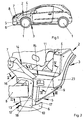
- FIG. 1 shows a motor vehicle with wheels 1 and with a front construction 2.
- the front construction 2 is shown schematically in FIG. 1 and has a strut 4 guided over a wheel recess 3 and pointing in the direction of travel.
- the end of the strut 4 pointing in the direction of travel is provided with a coupling device 5 connected.
- the coupling device 5 supports a front end of a subframe 6.
- the subframe 6 is preferably designed annular and holds an internal combustion engine, not shown, of the motor vehicle.
- the coupling device 5 holds a front element 7 of the front structure 2 and a bumper 8.
- FIG. 2 shows in a perspective view the coupling device 5 arranged on one side of the motor vehicle from FIG
- the coupling device 5 has a free end of the guided over the Radausappelung 3 strut 4 occlusive and guided to the subframe 6 thrust element 9 and the bumper 8 halterndes, guided to the subframe 6 closing element 10.
- the thrust element connects the guided over the Radausappelung 3 strut 4 with other areas of a frame 11 of the motor vehicle.
- the coupling device 5 has a support 12 with a box-shaped support section 13 for connecting the subframe 6 and a boom 14 for connection of the front element 7.
- the coupling device 5 has a box-shaped also cross-section 15, which is guided by the guided over the Radaus Principleung 3 strut 4 up to the support profile 13 is guided.
- a likewise box-shaped boom profile 16 of the boom 14 is guided to the front element 7.
- the thrust element 9 and the closing element 10 are connected to each other via a U-shaped support member 17 of the support 12 and held at a distance from each other.
- the thrust element 9, the closure element 10 and the support member 17 generate the box-shaped support section 13.
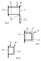
- FIG. 3 shows in a sectional illustration through the support 12 from FIG. 2 along the line III-III, the U-shaped support part 17 has bends 19 for connection to the push element 9 and the closure element 10.
- the push element 9 also has an angled portion 20 to his stiffening.
- In the sectional view of the U-shaped support member 17 only legs are shown. A base connecting the legs lies behind the drawing plane close to the auxiliary frame 6 shown in FIG.
- FIG. 4 shows the transverse profile 15 from FIG. 2 in a sectional view along the line IV-IV from FIG. 2. It can be seen here that the transverse profile 15 likewise has a U-shaped sheet metal part 21 which is connected to the thrust element 9 via angled portions 22 , The end of the transverse profile 15 is covered by a side plate 23 of the strut 4 shown in Figure 2, guided over the Radausnaturalung 3.
- FIG. 5 shows, in a sectional representation through the arm 14 from FIG. 2 along the line V - V, that the boom profile 16 has a U-shaped sheet metal part 24, which is connected to the closing element 10.
Landscapes
- Engineering & Computer Science (AREA)
- Chemical & Material Sciences (AREA)
- Combustion & Propulsion (AREA)
- Transportation (AREA)
- Mechanical Engineering (AREA)
- Body Structure For Vehicles (AREA)
- Filling Or Discharging Of Gas Storage Vessels (AREA)
Applications Claiming Priority (1)
| Application Number | Priority Date | Filing Date | Title |
|---|---|---|---|
| DE200610052383 DE102006052383A1 (de) | 2006-11-07 | 2006-11-07 | Vorderbau für ein Kraftfahrzeug |
Publications (1)
| Publication Number | Publication Date |
|---|---|
| EP1920996A1 true EP1920996A1 (fr) | 2008-05-14 |
Family
ID=38983762
Family Applications (1)
| Application Number | Title | Priority Date | Filing Date |
|---|---|---|---|
| EP07021165A Withdrawn EP1920996A1 (fr) | 2006-11-07 | 2007-10-30 | Structure avant pour un véhicule automobile |
Country Status (3)
| Country | Link |
|---|---|
| EP (1) | EP1920996A1 (fr) |
| DE (1) | DE102006052383A1 (fr) |
| WO (1) | WO2008055637A1 (fr) |
Families Citing this family (1)
| Publication number | Priority date | Publication date | Assignee | Title |
|---|---|---|---|---|
| DE102018212137A1 (de) * | 2018-07-20 | 2020-01-23 | Bayerische Motoren Werke Aktiengesellschaft | Tankanordnung |
Citations (2)
| Publication number | Priority date | Publication date | Assignee | Title |
|---|---|---|---|---|
| EP1281603A2 (fr) * | 2001-07-31 | 2003-02-05 | Nissan Motor Company, Limited | Structure avant de véhicule automobile |
| DE10309627A1 (de) * | 2003-03-04 | 2004-09-23 | Audi Ag | Tragstruktur eines Kraftfahrzeugs mit einer Frontlängsträger aufweisenden Fronttragstruktur |
Family Cites Families (7)
| Publication number | Priority date | Publication date | Assignee | Title |
|---|---|---|---|---|
| US2564295A (en) * | 1946-07-30 | 1951-08-14 | Phillips Petroleum Co | Relieving pressure vessels when subjected to high temperatures |
| DE2704961C2 (de) * | 1977-02-07 | 1982-06-16 | Johann Baptist Rombach Gmbh & Co Kg, 7500 Karlsruhe | Dichtungsanordnung |
| GB2029050A (en) * | 1978-08-17 | 1980-03-12 | Birkett Ltd S | Improvements in or Relating to Pressure Relief Valves |
| US4972965A (en) * | 1989-03-14 | 1990-11-27 | Swiss Aluminium Ltd. | Protective device for gas pressure vessels |
| CH681170A5 (fr) * | 1989-08-08 | 1993-01-29 | Alusuisse Lonza Services Ag | |
| US5848604A (en) * | 1997-10-29 | 1998-12-15 | Technical Products Group, Inc. | Thermally responsive pressure relief system |
| US6382232B1 (en) * | 2001-03-09 | 2002-05-07 | Dynetek Industries Ltd. | Remote triggering system and retrofit kit for thermal-pressure relief devices |
-
2006
- 2006-11-07 DE DE200610052383 patent/DE102006052383A1/de not_active Withdrawn
-
2007
- 2007-10-30 EP EP07021165A patent/EP1920996A1/fr not_active Withdrawn
- 2007-11-05 WO PCT/EP2007/009565 patent/WO2008055637A1/fr not_active Ceased
Patent Citations (2)
| Publication number | Priority date | Publication date | Assignee | Title |
|---|---|---|---|---|
| EP1281603A2 (fr) * | 2001-07-31 | 2003-02-05 | Nissan Motor Company, Limited | Structure avant de véhicule automobile |
| DE10309627A1 (de) * | 2003-03-04 | 2004-09-23 | Audi Ag | Tragstruktur eines Kraftfahrzeugs mit einer Frontlängsträger aufweisenden Fronttragstruktur |
Also Published As
| Publication number | Publication date |
|---|---|
| WO2008055637A1 (fr) | 2008-05-15 |
| DE102006052383A1 (de) | 2008-05-15 |
Similar Documents
| Publication | Publication Date | Title |
|---|---|---|
| DE10314905B4 (de) | Stoßfängersystem für engen Bauraum | |
| EP2773549B1 (fr) | Châssis auxiliaire muni de moulures | |
| DE102004012804B4 (de) | Kraftfahrzeuglängsträger | |
| DE102016121254B4 (de) | Batterieträger mit Toleranzausgleichselement | |
| DE102008020694A1 (de) | Kraftfahrzeugrahmen | |
| EP2540575A2 (fr) | Agencement de pare-chocs pour un véhicule automobile | |
| DE102019134712B4 (de) | Karosserieteilstruktur für ein wenigstens teilweise batteriebetriebenes Kraftfahrzeug | |
| DE102009050495A1 (de) | Hilfsrahmen | |
| DE102010020304A1 (de) | Hilfsträger | |
| DE102009028447A1 (de) | Abgasrohranordnung für ein Fahrzeug | |
| DE102010021574A1 (de) | Vorderbau für ein Kraftfahrzeug | |
| DE102008013832A1 (de) | Energie absorbierendes Verbindungselement | |
| EP1880924B1 (fr) | Poutre en tant que traverse ou longeron dans un véhicule automobile | |
| DE102012023946A1 (de) | Querträger, insbesondere Stirnwandquerträger für ein Kraftfahrzeug und korrespondierende Stirnwandstruktur | |
| WO2006079482A1 (fr) | Composant de carrosserie d'un vehicule | |
| EP3348457B1 (fr) | Appui de renforcement pour un véhicule automobile | |
| DE102013002537A1 (de) | Schweller-Bodenstruktur-Anordnung | |
| DE102009039805A1 (de) | Vorderbau zur Verbindung mit einer Karosserie eines Kraftfahrzeuges | |
| EP1920996A1 (fr) | Structure avant pour un véhicule automobile | |
| DE202014004746U1 (de) | Verstärkungsmittel, Rahmenstruktur und Kraftfahrzeug | |
| DE102018211554B3 (de) | Fahrzeug mit einem Seitenschweller | |
| DE102020205713A1 (de) | Karosseriestruktur für ein Fahrzeug | |
| EP2289772B1 (fr) | Dispositif pour l'assemblage d'un élément porteur et une pièce coulée | |
| DE102015013708A1 (de) | Querträger für einen Stoßfänger eines Kraftwagens, Stoßfänger und Kraftwagen | |
| DE102004044476A1 (de) | Kraftfahrzeug |
Legal Events
| Date | Code | Title | Description |
|---|---|---|---|
| PUAI | Public reference made under article 153(3) epc to a published international application that has entered the european phase |
Free format text: ORIGINAL CODE: 0009012 |
|
| AK | Designated contracting states |
Kind code of ref document: A1 Designated state(s): AT BE BG CH CY CZ DE DK EE ES FI FR GB GR HU IE IS IT LI LT LU LV MC MT NL PL PT RO SE SI SK TR |
|
| AX | Request for extension of the european patent |
Extension state: AL BA HR MK RS |
|
| 17P | Request for examination filed |
Effective date: 20081114 |
|
| AKX | Designation fees paid |
Designated state(s): AT BE BG CH CY CZ DE DK EE ES FI FR GB GR HU IE IS IT LI LT LU LV MC MT NL PL PT RO SE SI SK TR |
|
| 17Q | First examination report despatched |
Effective date: 20090109 |
|
| STAA | Information on the status of an ep patent application or granted ep patent |
Free format text: STATUS: THE APPLICATION IS DEEMED TO BE WITHDRAWN |
|
| 18D | Application deemed to be withdrawn |
Effective date: 20090520 |