EP1921012B1 - Konstruktionsverfahren für eine modulare Tafel - Google Patents
Konstruktionsverfahren für eine modulare Tafel Download PDFInfo
- Publication number
- EP1921012B1 EP1921012B1 EP07021926A EP07021926A EP1921012B1 EP 1921012 B1 EP1921012 B1 EP 1921012B1 EP 07021926 A EP07021926 A EP 07021926A EP 07021926 A EP07021926 A EP 07021926A EP 1921012 B1 EP1921012 B1 EP 1921012B1
- Authority
- EP
- European Patent Office
- Prior art keywords
- sheets
- frame
- container
- sheet
- arms
- Prior art date
- Legal status (The legal status is an assumption and is not a legal conclusion. Google has not performed a legal analysis and makes no representation as to the accuracy of the status listed.)
- Not-in-force
Links
Images

Classifications
-
- A—HUMAN NECESSITIES
- A47—FURNITURE; DOMESTIC ARTICLES OR APPLIANCES; COFFEE MILLS; SPICE MILLS; SUCTION CLEANERS IN GENERAL
- A47G—HOUSEHOLD OR TABLE EQUIPMENT
- A47G7/00—Flower holders or the like
-
- B—PERFORMING OPERATIONS; TRANSPORTING
- B65—CONVEYING; PACKING; STORING; HANDLING THIN OR FILAMENTARY MATERIAL
- B65D—CONTAINERS FOR STORAGE OR TRANSPORT OF ARTICLES OR MATERIALS, e.g. BAGS, BARRELS, BOTTLES, BOXES, CANS, CARTONS, CRATES, DRUMS, JARS, TANKS, HOPPERS, FORWARDING CONTAINERS; ACCESSORIES, CLOSURES, OR FITTINGS THEREFOR; PACKAGING ELEMENTS; PACKAGES
- B65D15/00—Containers having bodies formed by interconnecting or uniting two or more rigid, or substantially rigid, sections made of different materials
- B65D15/02—Containers having bodies formed by interconnecting or uniting two or more rigid, or substantially rigid, sections made of different materials of curved, or partially curved, cross-section, e.g. cans, drums
-
- A—HUMAN NECESSITIES
- A47—FURNITURE; DOMESTIC ARTICLES OR APPLIANCES; COFFEE MILLS; SPICE MILLS; SUCTION CLEANERS IN GENERAL
- A47G—HOUSEHOLD OR TABLE EQUIPMENT
- A47G19/00—Table service
- A47G19/12—Vessels or pots for table use
-
- A—HUMAN NECESSITIES
- A47—FURNITURE; DOMESTIC ARTICLES OR APPLIANCES; COFFEE MILLS; SPICE MILLS; SUCTION CLEANERS IN GENERAL
- A47G—HOUSEHOLD OR TABLE EQUIPMENT
- A47G7/00—Flower holders or the like
- A47G7/02—Devices for supporting flower-pots or cut flowers
- A47G7/06—Flower vases
-
- B—PERFORMING OPERATIONS; TRANSPORTING
- B22—CASTING; POWDER METALLURGY
- B22D—CASTING OF METALS; CASTING OF OTHER SUBSTANCES BY THE SAME PROCESSES OR DEVICES
- B22D19/00—Casting in, on, or around objects which form part of the product
- B22D19/0009—Cylinders, pistons
-
- B—PERFORMING OPERATIONS; TRANSPORTING
- B22—CASTING; POWDER METALLURGY
- B22D—CASTING OF METALS; CASTING OF OTHER SUBSTANCES BY THE SAME PROCESSES OR DEVICES
- B22D19/00—Casting in, on, or around objects which form part of the product
- B22D19/0045—Casting in, on, or around objects which form part of the product household utensils
-
- B—PERFORMING OPERATIONS; TRANSPORTING
- B22—CASTING; POWDER METALLURGY
- B22D—CASTING OF METALS; CASTING OF OTHER SUBSTANCES BY THE SAME PROCESSES OR DEVICES
- B22D19/00—Casting in, on, or around objects which form part of the product
- B22D19/04—Casting in, on, or around objects which form part of the product for joining parts
-
- B—PERFORMING OPERATIONS; TRANSPORTING
- B29—WORKING OF PLASTICS; WORKING OF SUBSTANCES IN A PLASTIC STATE IN GENERAL
- B29C—SHAPING OR JOINING OF PLASTICS; SHAPING OF MATERIAL IN A PLASTIC STATE, NOT OTHERWISE PROVIDED FOR; AFTER-TREATMENT OF THE SHAPED PRODUCTS, e.g. REPAIRING
- B29C33/00—Moulds or cores; Details thereof or accessories therefor
- B29C33/12—Moulds or cores; Details thereof or accessories therefor with incorporated means for positioning inserts, e.g. labels
-
- B—PERFORMING OPERATIONS; TRANSPORTING
- B29—WORKING OF PLASTICS; WORKING OF SUBSTANCES IN A PLASTIC STATE IN GENERAL
- B29C—SHAPING OR JOINING OF PLASTICS; SHAPING OF MATERIAL IN A PLASTIC STATE, NOT OTHERWISE PROVIDED FOR; AFTER-TREATMENT OF THE SHAPED PRODUCTS, e.g. REPAIRING
- B29C33/00—Moulds or cores; Details thereof or accessories therefor
- B29C33/12—Moulds or cores; Details thereof or accessories therefor with incorporated means for positioning inserts, e.g. labels
- B29C33/14—Moulds or cores; Details thereof or accessories therefor with incorporated means for positioning inserts, e.g. labels against the mould wall
-
- B—PERFORMING OPERATIONS; TRANSPORTING
- B29—WORKING OF PLASTICS; WORKING OF SUBSTANCES IN A PLASTIC STATE IN GENERAL
- B29C—SHAPING OR JOINING OF PLASTICS; SHAPING OF MATERIAL IN A PLASTIC STATE, NOT OTHERWISE PROVIDED FOR; AFTER-TREATMENT OF THE SHAPED PRODUCTS, e.g. REPAIRING
- B29C39/00—Shaping by casting, i.e. introducing the moulding material into a mould or between confining surfaces without significant moulding pressure; Apparatus therefor
- B29C39/02—Shaping by casting, i.e. introducing the moulding material into a mould or between confining surfaces without significant moulding pressure; Apparatus therefor for making articles of definite length, i.e. discrete articles
- B29C39/10—Shaping by casting, i.e. introducing the moulding material into a mould or between confining surfaces without significant moulding pressure; Apparatus therefor for making articles of definite length, i.e. discrete articles incorporating preformed parts or layers, e.g. casting around inserts or for coating articles
-
- B—PERFORMING OPERATIONS; TRANSPORTING
- B29—WORKING OF PLASTICS; WORKING OF SUBSTANCES IN A PLASTIC STATE IN GENERAL
- B29C—SHAPING OR JOINING OF PLASTICS; SHAPING OF MATERIAL IN A PLASTIC STATE, NOT OTHERWISE PROVIDED FOR; AFTER-TREATMENT OF THE SHAPED PRODUCTS, e.g. REPAIRING
- B29C45/00—Injection moulding, i.e. forcing the required volume of moulding material through a nozzle into a closed mould; Apparatus therefor
- B29C45/14—Injection moulding, i.e. forcing the required volume of moulding material through a nozzle into a closed mould; Apparatus therefor incorporating preformed parts or layers, e.g. injection moulding around inserts or for coating articles
- B29C45/14065—Positioning or centering articles in the mould
-
- B—PERFORMING OPERATIONS; TRANSPORTING
- B29—WORKING OF PLASTICS; WORKING OF SUBSTANCES IN A PLASTIC STATE IN GENERAL
- B29C—SHAPING OR JOINING OF PLASTICS; SHAPING OF MATERIAL IN A PLASTIC STATE, NOT OTHERWISE PROVIDED FOR; AFTER-TREATMENT OF THE SHAPED PRODUCTS, e.g. REPAIRING
- B29C45/00—Injection moulding, i.e. forcing the required volume of moulding material through a nozzle into a closed mould; Apparatus therefor
- B29C45/14—Injection moulding, i.e. forcing the required volume of moulding material through a nozzle into a closed mould; Apparatus therefor incorporating preformed parts or layers, e.g. injection moulding around inserts or for coating articles
- B29C45/14336—Coating a portion of the article, e.g. the edge of the article
-
- B—PERFORMING OPERATIONS; TRANSPORTING
- B29—WORKING OF PLASTICS; WORKING OF SUBSTANCES IN A PLASTIC STATE IN GENERAL
- B29C—SHAPING OR JOINING OF PLASTICS; SHAPING OF MATERIAL IN A PLASTIC STATE, NOT OTHERWISE PROVIDED FOR; AFTER-TREATMENT OF THE SHAPED PRODUCTS, e.g. REPAIRING
- B29C45/00—Injection moulding, i.e. forcing the required volume of moulding material through a nozzle into a closed mould; Apparatus therefor
- B29C45/14—Injection moulding, i.e. forcing the required volume of moulding material through a nozzle into a closed mould; Apparatus therefor incorporating preformed parts or layers, e.g. injection moulding around inserts or for coating articles
- B29C45/14467—Joining articles or parts of a single article
-
- B—PERFORMING OPERATIONS; TRANSPORTING
- B29—WORKING OF PLASTICS; WORKING OF SUBSTANCES IN A PLASTIC STATE IN GENERAL
- B29C—SHAPING OR JOINING OF PLASTICS; SHAPING OF MATERIAL IN A PLASTIC STATE, NOT OTHERWISE PROVIDED FOR; AFTER-TREATMENT OF THE SHAPED PRODUCTS, e.g. REPAIRING
- B29C70/00—Shaping composites, i.e. plastics material comprising reinforcements, fillers or preformed parts, e.g. inserts
- B29C70/68—Shaping composites, i.e. plastics material comprising reinforcements, fillers or preformed parts, e.g. inserts by incorporating or moulding on preformed parts, e.g. inserts or layers, e.g. foam blocks
- B29C70/681—Component parts, details or accessories; Auxiliary operations
- B29C70/682—Preformed parts characterised by their structure, e.g. form
-
- B—PERFORMING OPERATIONS; TRANSPORTING
- B29—WORKING OF PLASTICS; WORKING OF SUBSTANCES IN A PLASTIC STATE IN GENERAL
- B29C—SHAPING OR JOINING OF PLASTICS; SHAPING OF MATERIAL IN A PLASTIC STATE, NOT OTHERWISE PROVIDED FOR; AFTER-TREATMENT OF THE SHAPED PRODUCTS, e.g. REPAIRING
- B29C70/00—Shaping composites, i.e. plastics material comprising reinforcements, fillers or preformed parts, e.g. inserts
- B29C70/68—Shaping composites, i.e. plastics material comprising reinforcements, fillers or preformed parts, e.g. inserts by incorporating or moulding on preformed parts, e.g. inserts or layers, e.g. foam blocks
- B29C70/685—Shaping composites, i.e. plastics material comprising reinforcements, fillers or preformed parts, e.g. inserts by incorporating or moulding on preformed parts, e.g. inserts or layers, e.g. foam blocks by laminating inserts between two plastic films or plates
- B29C70/686—Shaping composites, i.e. plastics material comprising reinforcements, fillers or preformed parts, e.g. inserts by incorporating or moulding on preformed parts, e.g. inserts or layers, e.g. foam blocks by laminating inserts between two plastic films or plates the inserts being sheets or documents, e.g. ID cards
-
- B—PERFORMING OPERATIONS; TRANSPORTING
- B29—WORKING OF PLASTICS; WORKING OF SUBSTANCES IN A PLASTIC STATE IN GENERAL
- B29C—SHAPING OR JOINING OF PLASTICS; SHAPING OF MATERIAL IN A PLASTIC STATE, NOT OTHERWISE PROVIDED FOR; AFTER-TREATMENT OF THE SHAPED PRODUCTS, e.g. REPAIRING
- B29C70/00—Shaping composites, i.e. plastics material comprising reinforcements, fillers or preformed parts, e.g. inserts
- B29C70/68—Shaping composites, i.e. plastics material comprising reinforcements, fillers or preformed parts, e.g. inserts by incorporating or moulding on preformed parts, e.g. inserts or layers, e.g. foam blocks
- B29C70/74—Moulding material on a relatively small portion of the preformed part, e.g. outsert moulding
-
- B—PERFORMING OPERATIONS; TRANSPORTING
- B29—WORKING OF PLASTICS; WORKING OF SUBSTANCES IN A PLASTIC STATE IN GENERAL
- B29C—SHAPING OR JOINING OF PLASTICS; SHAPING OF MATERIAL IN A PLASTIC STATE, NOT OTHERWISE PROVIDED FOR; AFTER-TREATMENT OF THE SHAPED PRODUCTS, e.g. REPAIRING
- B29C70/00—Shaping composites, i.e. plastics material comprising reinforcements, fillers or preformed parts, e.g. inserts
- B29C70/68—Shaping composites, i.e. plastics material comprising reinforcements, fillers or preformed parts, e.g. inserts by incorporating or moulding on preformed parts, e.g. inserts or layers, e.g. foam blocks
- B29C70/74—Moulding material on a relatively small portion of the preformed part, e.g. outsert moulding
- B29C70/76—Moulding on edges or extremities of the preformed part
- B29C70/763—Moulding on edges or extremities of the preformed part the edges being disposed in a substantial flat plane
-
- B—PERFORMING OPERATIONS; TRANSPORTING
- B29—WORKING OF PLASTICS; WORKING OF SUBSTANCES IN A PLASTIC STATE IN GENERAL
- B29D—PRODUCING PARTICULAR ARTICLES FROM PLASTICS OR FROM SUBSTANCES IN A PLASTIC STATE
- B29D22/00—Producing hollow articles
- B29D22/003—Containers for packaging, storing or transporting, e.g. bottles, jars, cans, barrels, tanks
-
- B—PERFORMING OPERATIONS; TRANSPORTING
- B65—CONVEYING; PACKING; STORING; HANDLING THIN OR FILAMENTARY MATERIAL
- B65D—CONTAINERS FOR STORAGE OR TRANSPORT OF ARTICLES OR MATERIALS, e.g. BAGS, BARRELS, BOTTLES, BOXES, CANS, CARTONS, CRATES, DRUMS, JARS, TANKS, HOPPERS, FORWARDING CONTAINERS; ACCESSORIES, CLOSURES, OR FITTINGS THEREFOR; PACKAGING ELEMENTS; PACKAGES
- B65D11/00—Containers having bodies formed by interconnecting or uniting two or more rigid, or substantially rigid, components made wholly or mainly of plastics material
- B65D11/02—Containers having bodies formed by interconnecting or uniting two or more rigid, or substantially rigid, components made wholly or mainly of plastics material of curved cross-section
-
- B—PERFORMING OPERATIONS; TRANSPORTING
- B65—CONVEYING; PACKING; STORING; HANDLING THIN OR FILAMENTARY MATERIAL
- B65D—CONTAINERS FOR STORAGE OR TRANSPORT OF ARTICLES OR MATERIALS, e.g. BAGS, BARRELS, BOTTLES, BOXES, CANS, CARTONS, CRATES, DRUMS, JARS, TANKS, HOPPERS, FORWARDING CONTAINERS; ACCESSORIES, CLOSURES, OR FITTINGS THEREFOR; PACKAGING ELEMENTS; PACKAGES
- B65D11/00—Containers having bodies formed by interconnecting or uniting two or more rigid, or substantially rigid, components made wholly or mainly of plastics material
- B65D11/10—Containers having bodies formed by interconnecting or uniting two or more rigid, or substantially rigid, components made wholly or mainly of plastics material of polygonal cross-section and all parts being permanently connected to each other
-
- B—PERFORMING OPERATIONS; TRANSPORTING
- B65—CONVEYING; PACKING; STORING; HANDLING THIN OR FILAMENTARY MATERIAL
- B65D—CONTAINERS FOR STORAGE OR TRANSPORT OF ARTICLES OR MATERIALS, e.g. BAGS, BARRELS, BOTTLES, BOXES, CANS, CARTONS, CRATES, DRUMS, JARS, TANKS, HOPPERS, FORWARDING CONTAINERS; ACCESSORIES, CLOSURES, OR FITTINGS THEREFOR; PACKAGING ELEMENTS; PACKAGES
- B65D15/00—Containers having bodies formed by interconnecting or uniting two or more rigid, or substantially rigid, sections made of different materials
- B65D15/22—Containers having bodies formed by interconnecting or uniting two or more rigid, or substantially rigid, sections made of different materials of polygonal cross-section
-
- B—PERFORMING OPERATIONS; TRANSPORTING
- B29—WORKING OF PLASTICS; WORKING OF SUBSTANCES IN A PLASTIC STATE IN GENERAL
- B29C—SHAPING OR JOINING OF PLASTICS; SHAPING OF MATERIAL IN A PLASTIC STATE, NOT OTHERWISE PROVIDED FOR; AFTER-TREATMENT OF THE SHAPED PRODUCTS, e.g. REPAIRING
- B29C45/00—Injection moulding, i.e. forcing the required volume of moulding material through a nozzle into a closed mould; Apparatus therefor
- B29C45/14—Injection moulding, i.e. forcing the required volume of moulding material through a nozzle into a closed mould; Apparatus therefor incorporating preformed parts or layers, e.g. injection moulding around inserts or for coating articles
- B29C45/14336—Coating a portion of the article, e.g. the edge of the article
- B29C45/14344—Moulding in or through a hole in the article, e.g. outsert moulding
-
- B—PERFORMING OPERATIONS; TRANSPORTING
- B29—WORKING OF PLASTICS; WORKING OF SUBSTANCES IN A PLASTIC STATE IN GENERAL
- B29L—INDEXING SCHEME ASSOCIATED WITH SUBCLASS B29C, RELATING TO PARTICULAR ARTICLES
- B29L2031/00—Other particular articles
- B29L2031/712—Containers; Packaging elements or accessories, Packages
- B29L2031/713—Baskets
Definitions
- the present invention relates to a method of constructing objects out of modular panels or sheets of material.
- sheets of steel, aluminium, silver or copper between 0.3 mm and 5mm thick have been used in the construction of the both domestic and commercial objects; for example, vases, bowls, containers, fruit bowls, work surfaces, cookers and refrigerators.
- Sheet metal is generally used in the construction of such objects because it is aesthetically pleasing, is easy to clean, it is very versatile and allows a large number of different construction techniques and shaping methods to be used.
- the surface of the sheet metal can be damaged.
- any damage to the surfaces of the sheet metal can be detrimental to the value of the object. Processes which are required to remove any of this damage increase the expense of producing the object along with quantity of equipment which is required - for example, in some cases it is necessary to use sand or bead blasting on damaged surfaces of an object to remove the unsightly marks caused by welding or soldering; this process requires additional equipment and is labour intensive.
- Document DE-A-2 750 982 discloses a container structure comprising a frame made of two pieces of mouldable material.
- the present invention seeks to ameliorate the problems associated with the prior art by providing a method of constructing complex objects in a modular manner, requiring fewer complicated working steps and less raw material.
- one aspect of the present invention provides a modularly constructed container comprising: a frame formed from a single piece of mouldable material; and two or more rigid sheets of material, each having at least part of one edge embedded in the frame so that the two or more sheets of material are held in place by the frame to form a receptacle wherein the two or more sheets of material include one or more fixing holes which are at least partially filled with the mouldable material of the frame and the one or more fixing holes are through only part of an entire thickness of the sheet of material in which they are included.
- the two or more sheets of material are curved.
- the frame comprises a base section and one or more arms extending therefrom.
- the base section includes a hole through its entire depth.
- the one or more arms extend at an angle relative to the plane of the base section.
- the arms are of substantially equal length.
- At least one of the arms is of a different length to the other arms.
- the one or more of the sheets of material each have a pair of opposing edges which are embedded in respective arms of the frame.
- each of the one or more sheets of material is embedded in the base section of the frame.
- the base section and sheets of material define a receptacle.
- At least one of the one or more sheets of material are substantially planar.
- At least one of the one or more sheets of material contains one or more attachment holes.
- a further object is received by at least one of the attachment holes.
- Another aspect of the present invention provides a method of manufacturing a container comprising the steps of: providing a mould having a mould body with one or more injection holes and one or more sheet receiving slots; providing two or more rigid sheets of material inserting at least part of one edge of each of the sheets of material into one or more of the sheet receiving slots; and injecting a mouldable material into the mould to form a frame so that least part of one edge of each of the sheets of material is embedded in the mouldable material of the frame to form a receptacle wherein the two or more sheets of material include one or more fixing holes which are at least partially filled with the mouldable material of the frame, the one or more fixing holes are through only part of an entire thickness of the sheet of material in which they are included, and the frame is formed from a single piece of mouldable material.
- the step of inserting comprises clamping the mould around the at least part of one edge of each of the sheets of material.
- the step of providing two or more rigid sheets of material comprises providing two or more curved sheets of material.
- the frame has a base section and one or more arms extending therefrom.
- the bass section includes a hole through its entire depth.
- the frame with one or more arms extend at an angle relative to the plane of the base section.
- the arms are of substantially equal length.
- At least one of the arms is of a different length to the other arms.
- the two or more of the sheets of material each have a pair of opposing edges which are embedded in respective arms of the frame.
- each of the two or more sheets of material is embedded in the base section of the frame.
- the base section and sheets of material define a receptacle.
- the step of providing two or more sheets of material comprises the step of providing at least one sheet of sheet metal.
- the step of providing two or more sheets of material comprises the step of providing at least one sheet of a plastic material.
- the step of providing two or more sheets of material comprises the step of providing at least one sheet of slate.
- the step of providing two or more sheets of material comprises the step of providing at least one planar sheet of material.
- the step of providing two or more sheets of rigid material comprises the step of providing at least one of the two or more sheets of material having a depth of 0.3 mm to 5mm.
- One embodiment of the present invention comprises a method of manufacturing an object out of modular sections of material secured together using a frame of plastic material.
- Another embodiment of the present invention comprises an object manufactured according to the aforementioned method.
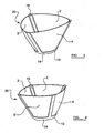
- FIG. 1 this figure shows a fruit bowl 1 constructed out of sheet metal according to the prior art methods.
- the fruit bowl 1 comprises five separate sheets of sheet metal 2-6: four of the sheet metal sheets are truncated triangular shaped sections of sheet metal 2-5; the fifth sheet metal sheet 6 is a square shaped section of sheet metal.
- Each sheet of sheet metal 2-6 preferably has a thickness between 0.3 mm and 5mm thick.
- each sheet of sheet metal 2-6 has a thickness between 0.3 mm and 3.5mm.
- Each of the truncated triangular sections 2-5 has two angled side edges 7,8 which extend from a long base edge 9 to a short top edge 10 - the short top edge 10 being the edge along which the triangle has been truncated.
- the length of the short top edge 10 is substantially equal to the length of one of the sides 11 of the square section 6 of sheet metal of the prior art bowl 1 described above.
- each of the four truncated triangular sections 2-5 are each secured to a respective edge 11 of the square sheet 6 along their short top edges 10.
- Each triangular section 2-5 is also secured, by welding or soldering, to two of the other truncated triangular sections 2-5 - one along each of the angled side edges 7,8; thus forming a shallow bowl 1.
- any of the welded joints 12 which may be visible to the end user must be polished and subjected to other treatments in order to maintain their aesthetic appearance and to remove any sharp or dangerous burrs.
- a fruit bowl 1 constructed according to an embodiment of the present invention is shown in figure 2 .
- the fruit bowl 1 shown in figure 2 comprises four truncated triangular sheets 2-5 of metal which are generally of the same dimensions as the truncated triangular sheets 2-5 of the fruit bowl 1 of the prior art (as shown in figure 1 ).
- truncated triangular sheets 2-5 of metal which are generally of the same dimensions as the truncated triangular sheets 2-5 of the fruit bowl 1 of the prior art (as shown in figure 1 ).
- fixing holes not shown
- fixing holes there are four or more such fixing holes on each side of the angled sides of each sheet 2-5.
- One or more similar fixing holes extend through the entire thickness of the triangular sheet 2-5 near the short top edge 10 thereof. It will be appreciated that in other embodiments of the present invention the fixing holes need not go through an entire depth of the sheet of material 2-5. Indeed, the fixing holes could comprise one or more etched or embossed lines or shapes in the surface of the sheet of material 2-5.
- a frame 13 of plastic material comprising a substantially square base section 14 with four elongate plastic arms 15 extending radially away from the base section 14 from each corner thereof. Each of the arms 15 extend at the same angle of elevation away from the plane of the base section 14.
- the space defined between each arm 15, one of the adjacent arms 15, and the square base section 14 of the frame 13 is generally the same shape as, but smaller than, one of the truncated triangular sheets 2-5.
- the frame 13 is preferably manufactured out of thermoplastic material. It will be appreciated that a large number of different colour and texture variations can be achieved by utilising different materials for construction of the frame 13 or varying additives which are incorporated into the material used to construct the frame 13. Materials other than plastics can be used in the construction of objects in accordance with the present invention. In particular, it may be necessary to alter the material of the frame 13 in order to suit the nature of the sheets of material 2-5 being held by the frame 13.
- the frame 13 and truncated triangular sheets 2-5 are secured together such that three edges 7,8,10 of each of the truncated triangular sheets 2-5 are embedded in the frame 13, the short top edge 10 thereof being embedded in the square base section 14, and each angled side edge 7,8 being embedded in a different arm 15 of the frame 13.
- the frame 13 has a first, a second, a third and a fourth arm 15; the first and second arms 15 extend from opposing corners of the square base 14 section, one from each end of a first edge of the square base section 14. Similarly, the second and third arms 15 of the frame 13 extend from opposing corners of the square base section 14, one from each end of a second edge of the base section 14. As will be appreciated, there are thus four edges of the square base section 14 and at the ends of each edge, an arm 15 extends.
- a first truncated triangular sheet 2 is embedded in the frame 13 such that a first angled side edge 7 thereof is embedded in the first arm 15 of the frame 13 and a second angled side edge 8 thereof is embedded in the second arm 15 of the frame 13.
- the short top edge 10 of the first truncated triangular sheet 2 is embedded in the first edge of the square base section 14 of the frame 13. This construction is repeated around the frame 13 with a second truncated triangular sheet 3 being embedded in the second and third arms 15 of the frame 13 and the second edge of the square base section 14, and so on.
- the truncated triangular sheets 2-5 are embedded in the plastic to the extent that the fixing holes which extend through the depth thereof are at least partially filled with the plastic of the frame 13.
- edges of the truncated triangular sheets 2-5 may be embedded in the frame 13 and that the disparate ends of the arms may be linked together by further arms.
- a fruit bowl 1 can be formed with a minimum amount of welding, polishing and de-burring of the individual sheets of metal which are used in its construction (all of which are complicated and expensive processes).
- the present invention can be utilised to manufacture a large number of different objects that would have previously been constructed out of sheets of material. Indeed, the present invention allows alternative materials to be used to manufacture such objects that would not have previously been considered; for example, slate.
- the alternative materials also include materials which are difficult to work, of a high value, or difficult to secure to other materials.
- the sheets of material are preferably rigid but it is envisaged that the objects may be made having sheets of non-rigid material, for instance canvas, paper or flexible plastic, if the supporting frame is sufficiently strong.
- Figure 3 shows a first type of bowl 20 comprising a frame 13 with three arms 15, and three sheets of material 2-4. Each sheet of material 2-4 is curved and embedded in the frame 13 along three edges.
- Figure 4 shows a second type of bowl 30 similar to the first type of bowl 20 but having a frame 13 with four arms 15, and four sheets of material 2-5.
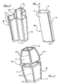
- Figure 5 shows a first type of vase 40 comprising a frame 13 and a number of generally rectangular sheets of material 2.
- the sheets 2 and frame 13 are arranged to form a vase 40 with a large number of side surfaces. It will be understood that prior methods of constructing such an object would require large amounts of welding, polishing and sand-blasting. All of these processes are expensive and require specialist equipment.
- Figure 6 shows a second type of vase 50 with a frame 13 having two arms 15 and two sheets 2,3 of material.
- the sheets 2,3 of material are embedded in the frame 13 and curve to form a receptacle.
- Figure 7 shows a third type of vase 60 having and upper 61 and a lower 62 portion. Both portions 61,62 are constructed in accordance with the present invention. The upper portion 61 is detachable from the lower portion 62 and both portions can be used separately or, when attached to each other, as one vase 60.
- attachment holes there are one or more attachment holes (not shown) in each of the truncated triangular sheets 2-5.
- These attachment holes can be used to attach various other objects 16 and features to the truncated triangular sections 2-5.
- the attachment holes could be used to secure rubber pads 16 to the truncated triangular sheets 2-5. These rubber pads 16 provide additional friction between the fruit bowl 1 and any fruit (not shown) held therein; this can prevent the fruit from excessive movement within the bowl 1 or prevent the fruit from falling out of the bowl 1 when the bowl is, for example moved.
- the other objects 16 and features 16 could include ornaments.
- one or more of the attachment holes extend through an entire depth of the sheet of material 2-5.
- the one or more of the attachment holes could comprise an etched or embossed line or shape in the surface of the truncated triangular sheets 2-5 - the embossed or etched line or shape being suitable to allow one or more objects 16 to be attached to the truncated triangular sheets 2-5.
- each rubber pad 16 can comprise a piece of rubber of circular cross-section.
- the piece of rubber comprises three parts: two outer cushions and a central column connecting the two cushions - the diameter of the two outer cushions being larger than that of the column and generally large than the diameter of the attachment hole.
- the diameter of the column is generally equal to the diameter of the attachment hole.
- the rubber pad 16 can be placed over the attachment hole such that one of the cushions (the first cushion) rests on the area of the truncate triangular sheet 2-5 surrounding the attachment hole.
- the first cushion of the pad 16 is on one side of the sheet 2-5 and the second cushion is on the other side of the sheet 2-5 with the column section of the pad 16 being within the attachment hole. It will be appreciated that a secure fitting can be achieved by using a pad 16 which has a column with a height which is substantially equal to the depth of the sheet 2-5.
- Embodiments of the present invention include methods of manufacturing objects such as the fruit bowl 1 discussed above.
- an embodiment of the present invention comprising a method of manufacturing an object will be described in relation to the fruit bowl 1 of the above embodiment of the present invention.
- the truncated triangular sheets 2-5 as described above, are heated to a temperature which is substantially the same as the melting temperature of the thermoplastic material used to construct the frame 13.
- the truncated triangular sheets 2-5 are subsequently pressed into the frame 13, which softens upon contact with the metal of the truncated triangular sheets 2-5.
- the angled side edges 7,8 of the truncated triangular sheets 2-5 are pressed into two adjacent arms 15 of the frame 13.
- the short top edge 10 of each of the truncated triangular sheets 2-5 is pressed into a side edge of the square base section 14.
- the truncated triangular sheets 2-5 are, thus, pressed into the frame 15 until the fixing holes which extend through the depth of the truncated triangular sections 2-5 are within the frame 15.
- the truncated triangular sheets 2-5 are immovably embedded in the frame 15.
- the truncated sheets 2-5 and frame 15 are then left to cool and the thermoplastic of the frame 15 to harden.
- the truncated triangular sections 2-5 can be clamped in a fixed position relative to each other in the relative positions which they have in the completed fruit bowl 1.
- a mould (not shown) is clamped around the adjacent edges 7,8 of the truncated triangular sections 2-5 and around the square base area which is defined by the short top edges 10 of all four of the truncated triangular sections 2-5. Subsequently a plastic is injected into the mould thus securing the truncated triangular sheets 2-5 together.
- a mould in other embodiments of the present invention a mould is provided.
- the mould comprises a mould body having one or more injection holes and one or more sheet receiving slots.
- One or more sheets of material 2-5 are inserted into one or more of the sheet receiving slots such that at least part of one edge of each sheet 2-5 is within the mould body.
- a plastic material may then be injected into the mould body through the one or more injection holes.
- the plastic material will, thus, flow into the mould and any edges of sheets 2-5 which are within the mould body will be embedded in the plastic material.
- the plastic material can be allowed to set at least partially and the mould then removed. If necessary further setting processes can be applied to the object to set the frame 13 of plastic material. It may be necessary to clamp the sheets of material 2-5 in a fixed position with respect to the mould.
- thermoplastic Although the embodiments of the invention which have been described above recite the use of thermoplastic, it will be appreciated that some embodiments of the present invention could utilise other types of plastic - such as thermosetting plastic.
- the frames 13 discussed above are described as constructed from a plastic material, it will be understood that the frames 13 could equally be constructed out of any mouldable material.
- the frames 13 which are used in the construction of objects according to the present invention can be manufactured out of any suitable mouldable material including: general purpose polystyrene (GPPS), high impact polystyrene (HIPS), acrylonitrile butadiene styrene (ABS), acrylonitrile styrene (SAN), butadiene styrene (BDS), methly-methacrylate styrene (MS), polymethly methacrylate (PMMA), polypropylene (PP), high-density polyethylene (HDPE), polyvinyl chloride (PVC), cellulose acetate (CA), cellulose nitrate (CN), polyethylene terephthalate (PETG), polyamide-6 (PA-6), polycarbonate (PC), polycarbonate+ABS (PC/ABS), polyacetal (POM), polythal
- references to a "mouldable material” include references to materials which are capable of being moulded (for example, when they are heated) and which, after moulding, are sufficiently stiff and viscous to hold a substantially fixed shape; of course, some flexibility in the frame may be advantageous.
- the frame 13 may be constructed out of a single piece of mouldable material.
- embodiments of the present invention relate to a fruit bowl 1 and methods of its manufacture.
- the present invention is, however, not limited to the production of fruit bowls 1.
- embodiments of the present invention include general modular construction methods using a frame and sheets of material. These methods can be applied to a large number of different objects which do not merely include household objects such as the vases and bowls shown in the figures (see figures 3 to 7 ); other objects to which the present invention is equally applicable include work surfaces, refrigerators, cases, computer cases, speaker cases, lamps and the like.
- the present invention is not limited to the construction of objects out of truncated triangular sheets of material; indeed, any shape of sheet material may be used in accordance with embodiments of the invention.
- the sheets of material can be processed prior to or after they are embedded in the frame; for example, the sheet material can be bent into a particular shape, polished, etched or painted.
- polishing is carried out before the sheets are embedded in the frame.
- etching of the sheets of material is carried out after they have been embedded into the frame.
- the base of the fruit bowl 1 was formed from a square base section 14 of the frame 13, it will be appreciated that this need not be the case.
- the base section 14 of the frame 13 could comprise a square section of plastic material with a hole through the entire depth thereof. A sheet of material could be embedded in the base section 14 to substantially or partially cover the hole therethrough.
- arms 15 of the frame 13 can be of different lengths, and extend away from the base section 14 of the frame 13 at different angles of elevation and take any desired arrangement of distribution around the base section 14.
- stock frames 13 can be manufactured for use in the construction of a particular object.
- the stock frames 13 can then be used in conjunction with sheets of a number of different materials in order to manufacture a variety of different products of the same generic type. Indeed, it will be understood that more than one type of sheet material can be used in conjunction with a single frame 13.
- the frame 13 is manufactured with one or more grooves or ridges which act as a guide of the embedding of one or more sheets or material therein.
- embodiments of the present invention can be used to form modularly constructed objects using thinner sheets of raw material with fewer difficult processing steps - thus, reducing the overall manufacturing costs for producing the objects.
- the term "embedded” may be defined as the moulding of a first material around at least a portion of, for example, a sheet of material. Specifically, the definition of the term should be distinguished from the sandwiching of a sheet of material between two portions of a first material.
Landscapes
- Engineering & Computer Science (AREA)
- Mechanical Engineering (AREA)
- Manufacturing & Machinery (AREA)
- Chemical & Material Sciences (AREA)
- Composite Materials (AREA)
- Laminated Bodies (AREA)
- Panels For Use In Building Construction (AREA)
- Making Paper Articles (AREA)
- Packaging Of Annular Or Rod-Shaped Articles, Wearing Apparel, Cassettes, Or The Like (AREA)
- Supplying Of Containers To The Packaging Station (AREA)
- Moulds For Moulding Plastics Or The Like (AREA)
- Steroid Compounds (AREA)
- Separation By Low-Temperature Treatments (AREA)
- Transition And Organic Metals Composition Catalysts For Addition Polymerization (AREA)
- Food-Manufacturing Devices (AREA)
- Blow-Moulding Or Thermoforming Of Plastics Or The Like (AREA)
Claims (15)
- Modular aufgebauter Behälter (1), umfassend:einen Rahmen (13), der aus einem einzigen Stück formbaren Materials ausgebildet ist; sowie zwei oder mehr starre Werkstoffbleche (2-6), wobei die jeweils zumindest einen Teil einer Kante aufweisen, die im Rahmen (13) eingebettet ist, so dass die zwei oder mehr Werkstoffbleche (2-6) von dem Rahmen (13) festgehalten werden, um ein Gefäß (1) zu bilden, wobei die zwei oder mehr Werkstoffbleche (2-6) ein oder mehrere Befestigungslöcher einschließen, die zumindest teilweise mit dem formbaren Material des Rahmens (13) gefüllt sind, und die zwei oder mehreren Befestigungslöcher nur durch einen Teil der Gesamtdicke des Werkstoffblechs (2-6) führen, in dem sie eingeschlossen sind.
- Behälter (1) nach Anspruch 1, wobei die zwei oder mehr Werkstoffbleche (2-6) gebogen sind.
- Behälter (1) nach irgendeinem vorhergehenden Anspruch, wobei der Rahmen (13) einen Basisabschnitt (14) und einen oder mehrere von demselben sich erstreckende Arme (15) umfasst.
- Behälter (1) nach Anspruch 3, wobei der Basisabschnitt (14) ein Loch durch seine gesamte Tiefe einschließt.
- Behälter (1) nach Anspruch 3 oder 4, wobei der eine oder die mehreren Arme (15) sich in einem Winkel relativ zur Ebene des Basisabschnitts (14) erstrecken.
- Behälter (1) nach irgendeinem der Ansprüche 3 bis 5, wobei die Arme (15) von im Wesentlichen gleicher Länge sind.
- Behälter (1) nach irgendeinem der Ansprüche 3 bis 5, wobei zumindest einer der Arme (15) von unterschiedlicher Länge zu den anderen Armen (15) ist.
- Behälter (1) nach irgendeinem der Ansprüche 3 bis 7, wobei die zwei oder mehr Werkstoffbleche (2-6) jeweils ein Paar gegenüberliegender Kanten aufweisen, die in jeweiligen Armen (15) des Rahmens (13) eingebettet sind.
- Behälter (1) nach Anspruch 8, wobei eine weitere Kante von jedem der zwei oder mehr Werkstoffbleche (2-6) im Basisabschnitt (14) des Rahmens (13) eingebettet ist.
- Behälter (1) nach Anspruch 8 oder 9, wobei der Basisabschnitt (14) und die Werkstoffbleche (2-6) ein Gefäß (1) begrenzen.
- Behälter (1) nach irgendeinem vorhergehenden Anspruch, wobei zumindest eines der zwei oder mehr Werkstoffbleche (2-6) im Wesentlichen plan sind.
- Behälter (1) nach irgendeinem vorhergehenden Anspruch, wobei zumindest eines der einen oder mehr Werkstoffbleche (2-6) ein oder mehrere Anbringungslöcher enthält.
- Behälter (1) nach Anspruch 12, wobei ein weiterer Gegenstand (16) von zumindest einem der Anbringungslöcher aufgenommen ist.
- Verfahren zur Herstellung eines Behälters (1), umfassend die folgenden Schritte:Vorsehen einer Form, die einen Formkörper mit einem oder mehreren Einspritzlöchern und einem oder mehreren blechaufnehmenden Schlitzen aufweist;Bereitstellen von zwei oder mehr starren Werkstoffblechen (2-6);Einfügen zumindest eines Teils einer Kante von jedem der Werkstoffbleche (2-6) in einen oder mehrere der blechaufnehmenden Schlitze; undEinspritzen eines formbaren Materials in die Form zur Ausbildung eines Rahmens (13), so dass zumindest ein Teil einer Kante von jedem der Werkstoffbleche (2-6) in das formbare Material des Rahmens (13) eingebettet ist, um ein Gefäß (1) zu bilden, wobei die zwei oder mehr Werkstoffbleche (2-6) ein oder mehrere Befestigungslöcher einschließen, die zumindest teilweise mit dem formbaren Material des Rahmens (13) gefüllt sind, das eine oder die mehreren Befestigungslöcher nur durch einen Teil der Gesamtdicke des Werkstoffblechs (2-6) führen, in dem sie eingeschlossen sind, und der Rahmen aus einem einzigen Stück formbaren Materials ausgebildet wird.
- Verfahren nach Anspruch 14, wobei der Schritt des Einfügens das Festklemmen der Form rund um den zumindest einen Teil einer Kante von jedem der Werkstoffbleche umfasst.
Applications Claiming Priority (1)
| Application Number | Priority Date | Filing Date | Title |
|---|---|---|---|
| GB0622467A GB2443611A (en) | 2006-11-10 | 2006-11-10 | Embedding a sheet in a frame |
Publications (2)
| Publication Number | Publication Date |
|---|---|
| EP1921012A1 EP1921012A1 (de) | 2008-05-14 |
| EP1921012B1 true EP1921012B1 (de) | 2011-12-07 |
Family
ID=37594716
Family Applications (1)
| Application Number | Title | Priority Date | Filing Date |
|---|---|---|---|
| EP07021926A Not-in-force EP1921012B1 (de) | 2006-11-10 | 2007-11-12 | Konstruktionsverfahren für eine modulare Tafel |
Country Status (7)
| Country | Link |
|---|---|
| US (1) | US20080110907A1 (de) |
| EP (1) | EP1921012B1 (de) |
| CN (1) | CN201309628Y (de) |
| AT (1) | ATE536314T1 (de) |
| ES (1) | ES2376120T3 (de) |
| GB (1) | GB2443611A (de) |
| HK (5) | HK1106661A2 (de) |
Families Citing this family (6)
| Publication number | Priority date | Publication date | Assignee | Title |
|---|---|---|---|---|
| US10022856B2 (en) | 2010-01-28 | 2018-07-17 | The Stanley Works Israel Ltd. | Metal and plastic container |
| DE202010002198U1 (de) * | 2010-02-10 | 2011-06-09 | Rotho Kunststoff Ag | Behälter |
| EP2420374A1 (de) * | 2010-08-20 | 2012-02-22 | Nestec S.A. | Spritzgussetikettierter Behälter |
| DE202012009628U1 (de) * | 2012-10-09 | 2012-11-14 | Robert Veit | Blechschale |
| GB2566328B (en) * | 2017-09-12 | 2020-02-12 | Bloom In Box Ltd | Receptacles |
| USD857460S1 (en) * | 2018-07-26 | 2019-08-27 | Radio Systems Corporation | Collapsible triangle bowl |
Family Cites Families (14)
| Publication number | Priority date | Publication date | Assignee | Title |
|---|---|---|---|---|
| US2604579A (en) * | 1939-06-01 | 1952-07-22 | Deneboudes Clement | Ice bucket |
| US2456929A (en) * | 1944-04-28 | 1948-12-21 | Woodall Industries Inc | Tray structure |
| GB1222908A (en) * | 1969-10-15 | 1971-02-17 | Ford Motor Co | Seats |
| IT975693B (it) * | 1972-11-10 | 1974-08-10 | Olivetti & Co Spa | Pannello e relativo collegamento amovibile ad esempio per contenito ri per ufficio |
| US4366905A (en) * | 1981-03-23 | 1983-01-04 | Syn-Trac Systems Inc. | Plastic material handling rack |
| JPH02147310A (ja) * | 1988-11-30 | 1990-06-06 | Konbi Kk | 網状織布を張設した合成樹脂成型品の製造方法 |
| FR2666496B1 (fr) * | 1990-09-06 | 1994-10-14 | Bruant Delahousse | Dispositif d'accrochage d'une bande de rappel notamment pour la coiffe d'un siege et coiffe munie d'un tel dispositif. |
| DE19615371C2 (de) * | 1996-04-19 | 1998-09-10 | Schott Glaswerke | Formkörper aus Glas oder Glaskeramik, eingefaßt in einem umspritzten Kunststoff-Halterahmen und Verfahren zum Einfassen des Formkörpers mit dem Halterahmen |
| US5638973A (en) * | 1996-05-09 | 1997-06-17 | Western Poly Corporation | Storage container with interlocking corner members |
| US6065600A (en) * | 1999-05-17 | 2000-05-23 | Chen; Hsing-Yi | Plate |
| CA2322673A1 (en) * | 2000-10-10 | 2002-04-10 | Grant Maxwell Coones | Knock-down container |
| US6419103B1 (en) * | 2001-04-17 | 2002-07-16 | Wen-Tsan Wang | Bamboo basket |
| DE20309214U1 (de) * | 2003-06-14 | 2004-10-21 | Maßgefertigte Koffer und Transportgehäuse, Spezialbeschläge GmbH | Rahmensystem zum Aufbau von Koffern u.dgl. Transportbehältern sowie damit aufgebauter Transportbehälter |
| DE202004007736U1 (de) * | 2004-05-11 | 2004-09-02 | Gebhardt Transport- Und Lagersysteme Gmbh | Behälter, insbesondere Isolierbehälter |
-
2006
- 2006-11-10 GB GB0622467A patent/GB2443611A/en not_active Withdrawn
-
2007
- 2007-11-08 HK HK07112195A patent/HK1106661A2/xx not_active IP Right Cessation
- 2007-11-08 HK HK07112194A patent/HK1106660A2/xx not_active IP Right Cessation
- 2007-11-08 HK HK07112197A patent/HK1106663A2/xx not_active IP Right Cessation
- 2007-11-08 US US11/936,992 patent/US20080110907A1/en not_active Abandoned
- 2007-11-08 HK HK07112196A patent/HK1106662A2/xx not_active IP Right Cessation
- 2007-11-09 CN CNU2007201934184U patent/CN201309628Y/zh not_active Expired - Lifetime
- 2007-11-12 EP EP07021926A patent/EP1921012B1/de not_active Not-in-force
- 2007-11-12 AT AT07021926T patent/ATE536314T1/de active
- 2007-11-12 ES ES07021926T patent/ES2376120T3/es active Active
- 2007-12-06 HK HK07113382A patent/HK1106659A2/xx not_active IP Right Cessation
Also Published As
| Publication number | Publication date |
|---|---|
| HK1106661A2 (zh) | 2008-03-14 |
| GB2443611A (en) | 2008-05-14 |
| CN201309628Y (zh) | 2009-09-16 |
| ES2376120T3 (es) | 2012-03-09 |
| HK1106659A2 (zh) | 2008-03-14 |
| ATE536314T1 (de) | 2011-12-15 |
| HK1106660A2 (zh) | 2008-03-14 |
| EP1921012A1 (de) | 2008-05-14 |
| HK1106662A2 (zh) | 2008-03-14 |
| GB0622467D0 (en) | 2006-12-20 |
| HK1106663A2 (zh) | 2008-03-14 |
| US20080110907A1 (en) | 2008-05-15 |
Similar Documents
| Publication | Publication Date | Title |
|---|---|---|
| EP1921012A1 (de) | Konstruktionsverfahren für eine modulare Tafel | |
| CN107756722B (zh) | 手机外壳及其制备方法 | |
| EP0514541A4 (en) | Method of manufacturing door trim of motor vehicle | |
| CN1108786A (zh) | 一体成型全圆式十字铃铛的制造方法 | |
| CN205165542U (zh) | 旋压组合模 | |
| CN201022408Y (zh) | 金属链成型编织机 | |
| JP2004181722A5 (de) | ||
| GB1599708A (en) | Composite articles | |
| US9630280B2 (en) | Method for producing single-sided mold and double-sided coining mold thereof | |
| CN216504549U (zh) | 一种模具加工用夹持装置 | |
| CN213485167U (zh) | 听筒装饰件及其制造模具 | |
| CN105563756A (zh) | 成型模具及该成型模具的制作方法 | |
| CN101862776B (zh) | 电子装置的壳体及其制造方法 | |
| CN222873174U (zh) | 一种五金件翻边攻牙装置 | |
| WO2003062709A8 (de) | Verfahren zur herstellung einer halterung | |
| CN216729133U (zh) | 一种异形多步成型模具 | |
| CN215303521U (zh) | 手镯镜面立体精密成型机 | |
| JP7774005B2 (ja) | 起伏状ポリマーパネルのトリミング | |
| KR101514632B1 (ko) | 사출 성형 방법 | |
| CN203901570U (zh) | 滑雪板模具 | |
| CN210758682U (zh) | 一种便于固定的塑料模具 | |
| CN210188267U (zh) | 一种精密模具用安装结构 | |
| CN206343530U (zh) | 带定位装置的汽车外覆盖件模具 | |
| KR101530588B1 (ko) | 락볼트 제조방법 | |
| CN104028626A (zh) | 一种盆架生产工艺 |
Legal Events
| Date | Code | Title | Description |
|---|---|---|---|
| PUAI | Public reference made under article 153(3) epc to a published international application that has entered the european phase |
Free format text: ORIGINAL CODE: 0009012 |
|
| AK | Designated contracting states |
Kind code of ref document: A1 Designated state(s): AT BE BG CH CY CZ DE DK EE ES FI FR GB GR HU IE IS IT LI LT LU LV MC MT NL PL PT RO SE SI SK TR |
|
| AX | Request for extension of the european patent |
Extension state: AL BA HR MK RS |
|
| 17P | Request for examination filed |
Effective date: 20081107 |
|
| AKX | Designation fees paid |
Designated state(s): AT BE BG CH CY CZ DE DK EE ES FI FR GB GR HU IE IS IT LI LT LU LV MC MT NL PL PT RO SE SI SK TR |
|
| 17Q | First examination report despatched |
Effective date: 20090209 |
|
| GRAP | Despatch of communication of intention to grant a patent |
Free format text: ORIGINAL CODE: EPIDOSNIGR1 |
|
| GRAS | Grant fee paid |
Free format text: ORIGINAL CODE: EPIDOSNIGR3 |
|
| GRAA | (expected) grant |
Free format text: ORIGINAL CODE: 0009210 |
|
| AK | Designated contracting states |
Kind code of ref document: B1 Designated state(s): AT BE BG CH CY CZ DE DK EE ES FI FR GB GR HU IE IS IT LI LT LU LV MC MT NL PL PT RO SE SI SK TR |
|
| REG | Reference to a national code |
Ref country code: GB Ref legal event code: FG4D |
|
| REG | Reference to a national code |
Ref country code: CH Ref legal event code: EP |
|
| REG | Reference to a national code |
Ref country code: IE Ref legal event code: FG4D |
|
| REG | Reference to a national code |
Ref country code: DE Ref legal event code: R096 Ref document number: 602007019176 Country of ref document: DE Effective date: 20120223 |
|
| REG | Reference to a national code |
Ref country code: ES Ref legal event code: FG2A Ref document number: 2376120 Country of ref document: ES Kind code of ref document: T3 Effective date: 20120309 |
|
| REG | Reference to a national code |
Ref country code: NL Ref legal event code: VDEP Effective date: 20111207 |
|
| PG25 | Lapsed in a contracting state [announced via postgrant information from national office to epo] |
Ref country code: LT Free format text: LAPSE BECAUSE OF FAILURE TO SUBMIT A TRANSLATION OF THE DESCRIPTION OR TO PAY THE FEE WITHIN THE PRESCRIBED TIME-LIMIT Effective date: 20111207 |
|
| LTIE | Lt: invalidation of european patent or patent extension |
Effective date: 20111207 |
|
| PG25 | Lapsed in a contracting state [announced via postgrant information from national office to epo] |
Ref country code: NL Free format text: LAPSE BECAUSE OF FAILURE TO SUBMIT A TRANSLATION OF THE DESCRIPTION OR TO PAY THE FEE WITHIN THE PRESCRIBED TIME-LIMIT Effective date: 20111207 Ref country code: SI Free format text: LAPSE BECAUSE OF FAILURE TO SUBMIT A TRANSLATION OF THE DESCRIPTION OR TO PAY THE FEE WITHIN THE PRESCRIBED TIME-LIMIT Effective date: 20111207 Ref country code: SE Free format text: LAPSE BECAUSE OF FAILURE TO SUBMIT A TRANSLATION OF THE DESCRIPTION OR TO PAY THE FEE WITHIN THE PRESCRIBED TIME-LIMIT Effective date: 20111207 Ref country code: LV Free format text: LAPSE BECAUSE OF FAILURE TO SUBMIT A TRANSLATION OF THE DESCRIPTION OR TO PAY THE FEE WITHIN THE PRESCRIBED TIME-LIMIT Effective date: 20111207 Ref country code: GR Free format text: LAPSE BECAUSE OF FAILURE TO SUBMIT A TRANSLATION OF THE DESCRIPTION OR TO PAY THE FEE WITHIN THE PRESCRIBED TIME-LIMIT Effective date: 20120308 |
|
| PG25 | Lapsed in a contracting state [announced via postgrant information from national office to epo] |
Ref country code: BE Free format text: LAPSE BECAUSE OF FAILURE TO SUBMIT A TRANSLATION OF THE DESCRIPTION OR TO PAY THE FEE WITHIN THE PRESCRIBED TIME-LIMIT Effective date: 20111207 Ref country code: CY Free format text: LAPSE BECAUSE OF FAILURE TO SUBMIT A TRANSLATION OF THE DESCRIPTION OR TO PAY THE FEE WITHIN THE PRESCRIBED TIME-LIMIT Effective date: 20111207 |
|
| PG25 | Lapsed in a contracting state [announced via postgrant information from national office to epo] |
Ref country code: EE Free format text: LAPSE BECAUSE OF FAILURE TO SUBMIT A TRANSLATION OF THE DESCRIPTION OR TO PAY THE FEE WITHIN THE PRESCRIBED TIME-LIMIT Effective date: 20111207 Ref country code: SK Free format text: LAPSE BECAUSE OF FAILURE TO SUBMIT A TRANSLATION OF THE DESCRIPTION OR TO PAY THE FEE WITHIN THE PRESCRIBED TIME-LIMIT Effective date: 20111207 Ref country code: IS Free format text: LAPSE BECAUSE OF FAILURE TO SUBMIT A TRANSLATION OF THE DESCRIPTION OR TO PAY THE FEE WITHIN THE PRESCRIBED TIME-LIMIT Effective date: 20120407 Ref country code: CZ Free format text: LAPSE BECAUSE OF FAILURE TO SUBMIT A TRANSLATION OF THE DESCRIPTION OR TO PAY THE FEE WITHIN THE PRESCRIBED TIME-LIMIT Effective date: 20111207 Ref country code: BG Free format text: LAPSE BECAUSE OF FAILURE TO SUBMIT A TRANSLATION OF THE DESCRIPTION OR TO PAY THE FEE WITHIN THE PRESCRIBED TIME-LIMIT Effective date: 20120307 |
|
| PG25 | Lapsed in a contracting state [announced via postgrant information from national office to epo] |
Ref country code: RO Free format text: LAPSE BECAUSE OF FAILURE TO SUBMIT A TRANSLATION OF THE DESCRIPTION OR TO PAY THE FEE WITHIN THE PRESCRIBED TIME-LIMIT Effective date: 20111207 Ref country code: PL Free format text: LAPSE BECAUSE OF FAILURE TO SUBMIT A TRANSLATION OF THE DESCRIPTION OR TO PAY THE FEE WITHIN THE PRESCRIBED TIME-LIMIT Effective date: 20111207 Ref country code: PT Free format text: LAPSE BECAUSE OF FAILURE TO SUBMIT A TRANSLATION OF THE DESCRIPTION OR TO PAY THE FEE WITHIN THE PRESCRIBED TIME-LIMIT Effective date: 20120409 |
|
| REG | Reference to a national code |
Ref country code: AT Ref legal event code: MK05 Ref document number: 536314 Country of ref document: AT Kind code of ref document: T Effective date: 20111207 |
|
| PLBE | No opposition filed within time limit |
Free format text: ORIGINAL CODE: 0009261 |
|
| STAA | Information on the status of an ep patent application or granted ep patent |
Free format text: STATUS: NO OPPOSITION FILED WITHIN TIME LIMIT |
|
| PG25 | Lapsed in a contracting state [announced via postgrant information from national office to epo] |
Ref country code: DK Free format text: LAPSE BECAUSE OF FAILURE TO SUBMIT A TRANSLATION OF THE DESCRIPTION OR TO PAY THE FEE WITHIN THE PRESCRIBED TIME-LIMIT Effective date: 20111207 |
|
| 26N | No opposition filed |
Effective date: 20120910 |
|
| REG | Reference to a national code |
Ref country code: DE Ref legal event code: R097 Ref document number: 602007019176 Country of ref document: DE Effective date: 20120910 |
|
| PG25 | Lapsed in a contracting state [announced via postgrant information from national office to epo] |
Ref country code: AT Free format text: LAPSE BECAUSE OF FAILURE TO SUBMIT A TRANSLATION OF THE DESCRIPTION OR TO PAY THE FEE WITHIN THE PRESCRIBED TIME-LIMIT Effective date: 20111207 |
|
| PG25 | Lapsed in a contracting state [announced via postgrant information from national office to epo] |
Ref country code: FI Free format text: LAPSE BECAUSE OF FAILURE TO SUBMIT A TRANSLATION OF THE DESCRIPTION OR TO PAY THE FEE WITHIN THE PRESCRIBED TIME-LIMIT Effective date: 20111207 |
|
| REG | Reference to a national code |
Ref country code: CH Ref legal event code: PL |
|
| PG25 | Lapsed in a contracting state [announced via postgrant information from national office to epo] |
Ref country code: LI Free format text: LAPSE BECAUSE OF NON-PAYMENT OF DUE FEES Effective date: 20121130 Ref country code: CH Free format text: LAPSE BECAUSE OF NON-PAYMENT OF DUE FEES Effective date: 20121130 |
|
| PG25 | Lapsed in a contracting state [announced via postgrant information from national office to epo] |
Ref country code: MT Free format text: LAPSE BECAUSE OF FAILURE TO SUBMIT A TRANSLATION OF THE DESCRIPTION OR TO PAY THE FEE WITHIN THE PRESCRIBED TIME-LIMIT Effective date: 20111207 |
|
| PG25 | Lapsed in a contracting state [announced via postgrant information from national office to epo] |
Ref country code: MC Free format text: LAPSE BECAUSE OF NON-PAYMENT OF DUE FEES Effective date: 20121130 Ref country code: TR Free format text: LAPSE BECAUSE OF FAILURE TO SUBMIT A TRANSLATION OF THE DESCRIPTION OR TO PAY THE FEE WITHIN THE PRESCRIBED TIME-LIMIT Effective date: 20111207 |
|
| PG25 | Lapsed in a contracting state [announced via postgrant information from national office to epo] |
Ref country code: LU Free format text: LAPSE BECAUSE OF NON-PAYMENT OF DUE FEES Effective date: 20121112 |
|
| PG25 | Lapsed in a contracting state [announced via postgrant information from national office to epo] |
Ref country code: HU Free format text: LAPSE BECAUSE OF FAILURE TO SUBMIT A TRANSLATION OF THE DESCRIPTION OR TO PAY THE FEE WITHIN THE PRESCRIBED TIME-LIMIT Effective date: 20071112 |
|
| REG | Reference to a national code |
Ref country code: FR Ref legal event code: PLFP Year of fee payment: 9 |
|
| PGFP | Annual fee paid to national office [announced via postgrant information from national office to epo] |
Ref country code: IE Payment date: 20160823 Year of fee payment: 10 Ref country code: GB Payment date: 20160902 Year of fee payment: 10 |
|
| REG | Reference to a national code |
Ref country code: FR Ref legal event code: PLFP Year of fee payment: 10 |
|
| PGFP | Annual fee paid to national office [announced via postgrant information from national office to epo] |
Ref country code: FR Payment date: 20161118 Year of fee payment: 10 Ref country code: DE Payment date: 20161121 Year of fee payment: 10 |
|
| PGFP | Annual fee paid to national office [announced via postgrant information from national office to epo] |
Ref country code: ES Payment date: 20161110 Year of fee payment: 10 Ref country code: IT Payment date: 20161123 Year of fee payment: 10 |
|
| REG | Reference to a national code |
Ref country code: DE Ref legal event code: R119 Ref document number: 602007019176 Country of ref document: DE |
|
| GBPC | Gb: european patent ceased through non-payment of renewal fee |
Effective date: 20171112 |
|
| REG | Reference to a national code |
Ref country code: FR Ref legal event code: ST Effective date: 20180731 |
|
| REG | Reference to a national code |
Ref country code: IE Ref legal event code: MM4A |
|
| PG25 | Lapsed in a contracting state [announced via postgrant information from national office to epo] |
Ref country code: IE Free format text: LAPSE BECAUSE OF NON-PAYMENT OF DUE FEES Effective date: 20171112 Ref country code: IT Free format text: LAPSE BECAUSE OF NON-PAYMENT OF DUE FEES Effective date: 20171112 Ref country code: DE Free format text: LAPSE BECAUSE OF NON-PAYMENT OF DUE FEES Effective date: 20180602 Ref country code: FR Free format text: LAPSE BECAUSE OF NON-PAYMENT OF DUE FEES Effective date: 20171130 |
|
| PG25 | Lapsed in a contracting state [announced via postgrant information from national office to epo] |
Ref country code: GB Free format text: LAPSE BECAUSE OF NON-PAYMENT OF DUE FEES Effective date: 20171112 |
|
| PG25 | Lapsed in a contracting state [announced via postgrant information from national office to epo] |
Ref country code: ES Free format text: LAPSE BECAUSE OF NON-PAYMENT OF DUE FEES Effective date: 20171113 |