EP1921230A2 - Cabine de grande taille pour le traitement, en particulier pour la pulvérisation et/ou le séchage de pièces à usiner - Google Patents
Cabine de grande taille pour le traitement, en particulier pour la pulvérisation et/ou le séchage de pièces à usiner Download PDFInfo
- Publication number
- EP1921230A2 EP1921230A2 EP07019308A EP07019308A EP1921230A2 EP 1921230 A2 EP1921230 A2 EP 1921230A2 EP 07019308 A EP07019308 A EP 07019308A EP 07019308 A EP07019308 A EP 07019308A EP 1921230 A2 EP1921230 A2 EP 1921230A2
- Authority
- EP
- European Patent Office
- Prior art keywords
- cabin
- ceiling
- walls
- elements
- module
- Prior art date
- Legal status (The legal status is an assumption and is not a legal conclusion. Google has not performed a legal analysis and makes no representation as to the accuracy of the status listed.)
- Granted
Links
- 238000001035 drying Methods 0.000 title claims abstract description 6
- 238000005507 spraying Methods 0.000 title claims abstract description 5
- 238000011282 treatment Methods 0.000 claims abstract description 6
- XLYOFNOQVPJJNP-UHFFFAOYSA-N water Substances O XLYOFNOQVPJJNP-UHFFFAOYSA-N 0.000 claims abstract description 5
- 229910052751 metal Inorganic materials 0.000 claims description 5
- 239000002184 metal Substances 0.000 claims description 5
- 239000000463 material Substances 0.000 claims description 4
- 230000006835 compression Effects 0.000 description 21
- 238000007906 compression Methods 0.000 description 21
- 239000003381 stabilizer Substances 0.000 description 6
- 238000005192 partition Methods 0.000 description 4
- 125000006850 spacer group Chemical group 0.000 description 4
- 238000009423 ventilation Methods 0.000 description 4
- 229910000831 Steel Inorganic materials 0.000 description 3
- 239000010959 steel Substances 0.000 description 3
- 239000002131 composite material Substances 0.000 description 2
- 238000010276 construction Methods 0.000 description 2
- 230000003014 reinforcing effect Effects 0.000 description 2
- 230000007704 transition Effects 0.000 description 2
- 229910052782 aluminium Inorganic materials 0.000 description 1
- XAGFODPZIPBFFR-UHFFFAOYSA-N aluminium Chemical compound [Al] XAGFODPZIPBFFR-UHFFFAOYSA-N 0.000 description 1
- 230000009977 dual effect Effects 0.000 description 1
- 230000002349 favourable effect Effects 0.000 description 1
- 239000012530 fluid Substances 0.000 description 1
- 239000011521 glass Substances 0.000 description 1
- 238000005286 illumination Methods 0.000 description 1
- 238000009434 installation Methods 0.000 description 1
- 238000012986 modification Methods 0.000 description 1
- 230000004048 modification Effects 0.000 description 1
- 238000003032 molecular docking Methods 0.000 description 1
- 238000000465 moulding Methods 0.000 description 1
- 239000003973 paint Substances 0.000 description 1
- 238000010422 painting Methods 0.000 description 1
- 239000007921 spray Substances 0.000 description 1
- 230000003068 static effect Effects 0.000 description 1
- 238000009966 trimming Methods 0.000 description 1
Images


Classifications
-
- E—FIXED CONSTRUCTIONS
- E04—BUILDING
- E04H—BUILDINGS OR LIKE STRUCTURES FOR PARTICULAR PURPOSES; SWIMMING OR SPLASH BATHS OR POOLS; MASTS; FENCING; TENTS OR CANOPIES, IN GENERAL
- E04H5/00—Buildings or groups of buildings for industrial or agricultural purposes
- E04H5/02—Buildings or groups of buildings for industrial purposes, e.g. for power-plants or factories
-
- B—PERFORMING OPERATIONS; TRANSPORTING
- B05—SPRAYING OR ATOMISING IN GENERAL; APPLYING FLUENT MATERIALS TO SURFACES, IN GENERAL
- B05B—SPRAYING APPARATUS; ATOMISING APPARATUS; NOZZLES
- B05B16/00—Spray booths
- B05B16/40—Construction elements specially adapted therefor, e.g. floors, walls or ceilings
Definitions
- the invention relates to a large-capacity cabin for the treatment, in particular for spraying and / or drying, of workpieces, in particular of power, rail, air or water vehicles, with at least two opposite cabin walls and a cabin ceiling.
- Well-known open-plan cabins are used where workpieces with relatively large areas have to be treated.
- workpieces with relatively large areas have to be treated.
- rail vehicles, buses and aircraft are pretreated in such large cabins, painted and dried.
- Object of the present invention is to design a large cubicle of the type mentioned so that it is easy to install and self-supporting.
- the cabin walls each have at least two vertical supports of open profile elements, which are connected to each other via wall elements, and the cabin ceiling at least two vertically extended lattice girder substantially of open profile elements, and the lattice girders facing each other Connect supports of the cabin walls such that the cabin walls and the car ceiling stabilize each other.
- the open profile elements are mutually stabilizingly connected to one another in such a way that they form a self-supporting skeleton for the large-capacity cabin. Massive walls or connections with the hall are therefore not required.
- Open profile elements preferably C- or U-shaped profile elements are lighter than closed profile elements, in particular hollow profiles, and also easy to produce from coil material by trimming and edges.
- they have in contrast to I-beams an interior, for example, for the implementation of lines, which is accessible from outside, and over which the profile elements can also be easily bolted or riveted to their walls.
- the cabin ceiling and / or the cabin walls can be composed of modules. In this way they can be preassembled at the factory, transported to the installation site and quickly and easily assembled into finished large capacity cabins.
- each cabin ceiling module may include one of the lattice girders, at least on the side adjacent to an adjacent cabin ceiling module, which is closely connected to the corresponding lattice girder of the adjacent cabin ceiling module.
- connections of the supports with the wall elements and the lattice girders can be releasably, in particular screwed. In this way, the large cubicle can be easily converted or dismantled.
- the wall elements may be SBS walls and / or C-walls that are lightweight, robust, and easy to install.
- the profile elements of the lattice girders may have U-shaped profiles so that they are particularly light but nevertheless stable.
- the profile elements of the supports may also have C-shaped profiles, so that they are transversely stable in all directions and have webs for securing the wall elements.
- the profile elements can be easily bent from flat material, in particular cut sheet metal Kant parts.
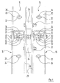
- FIG. 1 a generally provided with the reference numeral 10 ceiling-wall module of an otherwise not shown large capacity cabin for pretreatment, painting and drying of motor vehicles, rail, air and water vehicles is shown.
- the ceiling-wall module 10 comprises two opposite vertical cabin wall modules 12, which are connected to each other via a horizontal cabin ceiling module 14.
- the cabin ceiling of the full-size cabin is composed of a plurality of such cabin ceiling modules 14, and the cabin walls of the full-size cabin are composed of a plurality of cabin wall modules 12.
- the car ceiling module 14 has the shape of a cuboid box.
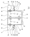
- the vertical, perpendicular to the cabin walls extending transverse sides (front and rear sides) of the car ceiling module 14 are each formed by a lattice girder 16, which expands in area.
- a second lattice girder 16 of an adjacent cabin ceiling module 14, which is otherwise not shown in FIG. 2, is additionally shown on the right of the cabin ceiling module 14.
- Each lattice girder 16 comprises a straight top band 18 and a straight bottom band 20 which extend in a horizontal direction parallel to each other and perpendicular to each other and perpendicular to the cabin walls.
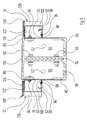
- FIG. 3 shows the two lattice girders 16 from FIG. 2 of the two adjacent cabin ceiling modules 14, which are screwed detachably by means of spacers 24 at a distance from one another with through-bolts 22, which in turn are shown in FIG. 4, so that a total of Lattice girder 16 is realized.
- the legs of the U of the upper band 18 and the lower band 20 are of different lengths.
- the upper band 18 and the lower band 20 are each open to the other band.
- the short legs of the upper belt 18 and the lower belt 20 are vertical and located on the inside of the cabin ceiling module 14 facing side.
- the closed base walls of the upper belt 18 and the lower belt 20 are arranged horizontally.
- the upper belt 18 and the lower belt 20 are connected to each other via twelve mutually parallel, perpendicular to the upper belt 18 and the lower belt 20 extending tension and compression rods 26 ( Figures 1 and 2).
- the tension and compression bars 26 are also cut Blechkantprofile with a doppelrechtwinkligen, U-shaped cross-section, which is apparent from Figure 4, wherein the legs of the tension and compression bars 26 are the same length.
- the legs of the tension and compression bars 26 are parallel to the legs of the upper belt 18 and the lower belt 20. Their base walls extend perpendicular to the legs and the base walls of the upper belt 18 and the lower belt 20th
- the distance of the outer surfaces of the two legs of the tension and compression rods 26 is smaller than the distance between the inner surfaces of the two legs of the upper belt 18 and the lower belt 20.
- Each pull and push rod 26 dives with its ends in the area between the legs of the upper belt 18th or the lower belt 20, wherein between the long leg of the upper belt 18 and the lower belt 20 and the corresponding leg of the tension and compression rod 26 each have an end of a tension rod 28 explained in more detail below is arranged.
- Each pull and push rod 26 is bolted to its two legs each with a through-bolt 30 shown in Figures 3, 4 and 6 with the corresponding leg of the upper belt 18 and the lower belt 20.
- the through-bolt 30 in the long legs of the upper belt 18 and the lower belt 20 also passes through the end of the corresponding tie rod 28 therethrough.
- the two outer pull and push rods 26a (FIG. 2), which are concealed in FIG. 1, terminate with the respective ends of the upper band 18 and the lower band 20 and thus bound the transverse sides of the lattice girder 16.
- the distances between the inner ten tension and compression bars 26 are the same size and slightly larger than the distances between the outer tension and compression bars 26 a and their respective adjacent inner tension and compression bars 26th
- tension rods 28 are flat elongated metal plates. They each extend obliquely from the upper band 18 facing the end of a tension and compression rod 26 to the lower band 20 facing the end of the other tension and compression rod 26. Those tension rods 28 which are connected to the outer tension and compression rods 26 a, each lead to their upper band 18 facing the end.
- the orientation relative to the tensile and compressive bars 26 of each of the next outer tensile bars 28 as viewed from the outer tensile and compression bars 26a towards the other outer tensile and compression bars 26a corresponds to the orientation of the respective outer tensile and spring bars Push rod 26a nearest outer tie rod 28a.
- the tie rod 28b located in the middle of the lattice girder 16 between the fifth and the sixth pull and push rods 26 is oriented so as to cross perpendicular to the transverse sides of the cabin ceiling module 14 with the corresponding tie bar 28b of the lattice girder 16 of the adjacent cabin ceiling module 14 , which is apparent from Figure 2.
- the base walls of the upper belt 18 and the lower belt 20 also have a plurality of visible in the figures 4 and 6 continuous slots 32.
- the elongated holes 32 are arranged lying in the transverse direction in the middle between the legs of the upper belt 18 and the lower belt 20. In their longitudinal directions, the elongated holes 32 are perpendicular to the median plane, ie perpendicular to the longitudinal direction of the upper band 18 or of the lower band 20. In the region of the tension and compression bars 26, two of the elongated holes 32 are arranged closely to one another at the same distance from the plane, which is perpendicular to the base wall of the upper belt 18 and the lower belt 20 and contains the axes of the through-bolts 30 at the ends of the tension and compression rods 26.
- the hidden in the figure 3 oblong holes in the upper bands 18 are used to carry through bolts 34 for fixing eleven flat trough-shaped, elongated ceiling elements 36.
- the cover elements 36 carry insulating elements and are closed at the top with lids.
- the elongated holes 32 in the lower bands 20 are used to carry out corresponding through-bolts 34 for fastening a total of eleven filter ceiling elements 38, lighting ceiling elements 40 and inner ceiling elements 42, which are shown in cross-section in Figure 5 and described in more detail below.
- the ceiling elements 36 are fastened in each case to their end regions on the upper belt 18 of the two lattice girders 16 of the cabin ceiling module 14. They lie there on the base walls of the upper bands 18.
- the ceiling elements 36 In the assembled state of the cabin ceiling module 14 (FIG. 1), the ceiling elements 36 extend horizontally.
- the width of the ceiling elements 36 corresponds to the distance between the two adjacent tension and compression bars 26, over which it is arranged.
- the two outer ceiling elements 36 are therefore narrower than the inner.
- the ceiling elements 36 are arranged close to each other and close the cabin ceiling module 14 tightly. Adjacent ceiling elements 36 are on their long sides screwed with through-bolts not shown in Figures 1 to 9.
- the narrow sides of the ceiling elements 36 project beyond the base walls of the upper strips 18 such that they abut against the narrow sides of the corresponding ceiling elements 36 of the adjacent cabin ceiling module 14 (FIG. 3).
- the adjoining ceiling elements 36 of adjacent cabin ceiling modules 14 are screwed at their end faces with through-bolts 44.
- the six filter ceiling elements 38, three lighting ceiling elements 40 and two interior ceiling elements 42 are arranged, all have the same outer dimensions as the corresponding ceiling elements 36 ( Figures 1, 2, 3 and 5).
- the filter cover elements 38 contain folded, filter elements supporting coil plates with recesses so that they are permeable to air.
- the recesses are about 150 mm x 150 mm in size. They are limited by bars, which have a web width of 10 mm.
- the lighting ceiling elements 40 carry known lighting elements for illuminating the cabin interior.
- the longitudinal edges of the filter cover elements 38, the lighting ceiling elements 40 and the inner ceiling elements 42 are aligned with the corresponding tension and compression bars 26.
- the inner ceiling elements 42 each adjoin the cabin walls.
- each inner ceiling element 42 is one of the lighting ceiling elements 40, which in each case a group of three filter ceiling elements 38 is adjacent. Between the two groups of filter element elements 38 lies the third illumination ceiling element 40.
- each group of filter ceiling elements 38 On both sides of each group of filter ceiling elements 38 a partition wall 46 shown in Figure 5 is arranged in each case, which runs parallel to the cabin walls.
- the partition walls 46 extend in the vertical direction from the corresponding filter cover elements 38 to the ceiling elements 36 and in the horizontal direction in each case up to the lattice girders 16.
- the partition walls 46 thus delimit, together with the filter ceiling elements 38 and the corresponding ceiling elements 36, a total of two ventilation channels 48, via which air can be supplied to the interior of the large-capacity cabin for ventilation through the filter ceiling elements 38.
- the central lighting ceiling element 40 together with the adjacent partitions 46 and the corresponding ceiling element 36, defines a central channel 50.
- the central channel 50 When the large-capacity cabin is used for handling aircraft fuselages, two below the central channel 50 project into the interior of the large-capacity cabin during operation the figures 1 to 9, not shown, rear channels for internal ventilation of the fuselage air supplied.
- the rear channels have jet nozzles, with which the air is blown horizontally into the cabin interior.
- the rear channels are each slidable to the nearest cabin wall to provide a passage for retracting the fuselage.
- the sides of the car ceiling module 14 that run perpendicular to the lattice girders 16 in the extension of the cabin walls are each closed by four plate-shaped side wall elements 52 (see FIG. Sidewall members 52 extend vertically across the entire height of cabin ceiling module 14 from inner liner member 42 to the corresponding outer liner member 36.
- the side wall elements 52 are placed close to each other and bolted to the corresponding inner ceiling element 42 and the corresponding ceiling element 36 with through bolts, not shown in FIGS. 1 to 9.
- the respective outer longitudinal edges of the two outer side wall elements 52 terminate shortly before the lattice girders 16. There, the respective outer pull and push rods 26a are freely accessible from the transverse side of the cabin ceiling module 14 and respectively abut against a support profile 56 of the cabin walls, of which the cabin roof module 14 is worn in the manner described below.
- a composite of the support profiles 56 of two adjacent cabin wall modules 12 double support 54 is shown in Figures 6 to 9 in different horizontal sections.
- the double support 54 carries the adjacent car ceiling modules 14.
- the horizontal sectional plane in FIG. 6 runs parallel to the cover elements 36 between the upper belts 18 and the lower belts 20 of the lattice girders 16 interconnected in the manner described above.
- the support profiles 56 have the shape of Blechkantprofilen with doppelrechtwinklige, approximately C-shaped, so open cross-sections. Double right angle C-shaped here means that the Blechkantprofile have a rectangular cross-section and one of the walls so interrupted in its center, that is open, that on both sides of the opening in each case a web 58 remains.
- the support profiles 56 face each other with their closed rear walls. They are closed at their ends in each case with a front plate 60; in the figures 6 to 9, only the end plates 60 on the cabin ceiling modules 14 facing away from the lower end face of the support profiles 56 are shown.
- the end plates 60 each have a central bore 62 for a screw, not shown, with which the double support 54 can be screwed to a hall floor or a hall ceiling.
- a sword 64 Between the rear walls of the two support profiles 56 is a sword 64, to which the lattice girders 16 of the cabin ceiling module 14 are attached.
- the sword 64 on one of the double supports 54 is shown in detail in FIG.
- the sword 64 is plate-shaped and made of sturdy material, such as steel. Viewed perpendicularly to the rear walls of the support profiles 56, the sword 64 is approximately rectangular. Its length in the longitudinal direction of the double support 54 corresponds to the distance between the mutually facing closed base walls of the upper bands 18 and the lower bands 20 of the lattice girders 16, as shown in Figures 1, 2 and 10. Its width parallel to the rear walls of the support profiles 56 is about twice as large as the local width of the support profiles 56 (FIG. 6). It protrudes about halfway, so over the entire width of the support profiles 56, in the limited by the two rear walls area.
- the blade 64 On its longitudinal side facing away from the double support 54, the blade 64 has a projection 70 shown in detail in FIG. 10 in the region of the long legs of the upper belts 18 and the lower belts 20.
- the projections 70 protrude beyond the otherwise straight longitudinal side of the sword 64.
- Each protrusion 70 projects beyond the long leg of the upper belt 18 or the lower belt 20 on its side facing the respective other protrusion 70 in the longitudinal direction of the sword 64.
- the upper belt 18 and the lower belt 20 are, as shown in Figure 6, respectively connected by the through-bolts 30 and further through-bolts 76 with the sword 64.
- the through-bolts 30 pass through the balancing plates 68 and the second continuous bore 74 in the sword 64 therethrough.
- the lattice girders 16 thus connect opposing double supports 54 of the cabin wall modules 12 in such a way that the cabin wall modules 12 and the cabin ceiling module 14 stabilize each other.
- the double support 54 is surrounded over its entire length with a cover.
- the cover is composed of an inner cover housing part 78 and an outer cover housing part 80, as shown in FIGS. 6 to 9.
- the inner cover housing part 78 surrounds the approximately half-area of the double support 54 facing the interior (FIGS. 6 to 9 above) of the large-capacity cabin from approximately the middle of the open wall of one support profile 56 to approximately the middle of the open wall of the other support profile 56.
- the inner cover housing part 78 is bent at right angles. In the area of the sword 64 it has a correspondingly dimensioned slot 82, shown in FIG. 6, through which the sword 64 passes.
- the inner cover housing part 78 is screwed with a plurality of through-bolts 84 with the interior of the large cabin facing webs 58 of the open walls of the support profiles 56. Between the webs 58 and the inner Abdeckgeophuseteil 78 each a spacer-compensating plate 85 is arranged with a suitable thickness.
- the heads of the through-bolts 84 are located in the respective interior of the support profiles 56.
- the length of the through-bolts 84 is dimensioned such that it additionally extends through a side edge of a coil plate 86 of a C-plate 88.
- the C-plate 88 is a plate that is folded double right angles at opposite edges.
- the C-plates 88 are in the direction perpendicular to the double supports 54 of equal width and in each case in the plane of the overlying side wall elements 52 of the cabin ceiling module 14 is arranged ( Figures 1 and 2).
- the inner cover housing part 78 is bent away from the double support 54 at right angles, so that in each case an attachment region 90 for the outer cover housing part 80 is realized.
- the attachment areas 90 is in the longitudinal direction the double support 54 a plurality of continuous, hidden in Figures 6 to 9 holes mounted at the cabin ceiling modules 14 openings facing each a nut 92 for a through-bolt 94 for fixing the outer Abdeckgephinuseteils 80 with a retaining spring 96 is held without the through-bolt 94 ,
- the outer Abdeckgekoruseteil 80 is constructed except for its mounting portions 98 corresponding to the inner Abdeckgekoruseteil 78.
- the outer Abdeckgekoruseteil 80 is not bolted to the interior of the large capacity cabin facing away from webs 58 on the open sides of the support profiles 56. Instead, it is placed on the outside of the double support 54, which faces away from the interior of the cabin, and is screwed to the attachment regions 90 of the inner cover housing part 78 at its attachment regions 98 with the push-through screws 94 described above.
- the outer cover housing part 80 continues in each case after a 90 ° bend in the direction of the interior of the large-capacity cabin and merges into an overlap area 100, which extends to a cover plate 102 for an insulating layer 104 of the C-plate 88 extends.
- the overlapping areas 100 conceal the corresponding side edges of the C-plates 88 and the above-mentioned screw connections with the webs 58 of the open walls of the support profiles 56.
- U-shaped stabilizers 106 are also arranged in the profile. Each stabilizer 106 extends in the longitudinal direction of the double supports 54 over the entire height of the coil plates 86. Its closed wall abuts against the abutting on the web 58 of the support section 56 region of the side edge of the coil plate 86.
- One leg of the stabilizer 106 abuts the leg of the coil plate 86 facing away from the cylinder and is bolted to this with through-bolts 108.
- the nuts for this through-bolts 108 are held with retaining springs in the unassembled state on the legs of the stabilizers 106, which facilitates assembly.
- the other leg presses against the inside of the cabin facing away from the surface of the cover plate 102 of the C-plate 88 and thus holds the insulating layer 104 on the inner wall of the coil plate 86 fixed.
- the sword 64 extends over the height of the cabin ceiling module 14. Below the sword 64, each double support 54 instead of the sword 64 a the thickness of the sword 64 corresponding spacer plate 110, which is shown in Figures 7 to 9.
- FIG. 7 shows a cross section of the double support 54 from FIG. 6 below the sword 64 in the region of the C plates 88.
- each one Reinforcing plate 112 arranged through which lead the local through-bolts 66.
- FIG. 8 shows a cross section of the double support 54 from FIGS. 6 and 7 below the C-plates 88 in the region of locking profiles 116 which connect the two double supports 54 of the corresponding cabin wall module 12 horizontally.
- Each bar profile 116 is connected to a side edge with a through-bolt 118 with the legs of the corresponding pillar profile 56 facing the cabin interior.
- each cabin wall module 12 comprises a spray booth system plate (SBS plate 120) which extends in a planar manner between the two double supports 54.
- SBS panels which are used as walls for cabins of a paint shop, are for example in the DE 197 39 642 C2 , Column 4, line 12 to column 6, line 4 described.
- Each SBS plate 120 has two extending in the longitudinal direction of the double supports 54 of the cabin wall module 12 SBS supports 122 ( Figure 9), where it is screwed analogously to the C-plates 88 with one of the double supports 54 of the cabin wall module 12.
- the SBS pillars 122 are made of sheet metal bent in cross section along a rectangle.
- the edge of the SBS supports 122 which corresponds to the interior of the cabin and the double support 54 of the cabin wall module 12 facing corner of the imaginary rectangle is missing.
- the wall adjacent to the overlap area 100 of the inner cover housing part 78 is bent in an approximately S-shaped manner such that it forms a kind of labyrinth with the overlapping area 100.
- the two SBS supports 122 of the SBS plate 120 carry a glass wall 124. In the region of their ends, the two SBS supports 122 are each connected by a horizontally extending transverse bar 126.
- the overlap area 100 of the outer cover housing part 80 is shorter in the area of the latching profiles 116 and SBS plates 120 shown in FIGS. 1, 2 and 9 than in the area of the C plates 88. This is necessary because the SBS plates 120 are thicker as the C-plates 88. In the area of the bar profiles 116, a transition to the respective SBS supports 122 of the SBS plates 120 is thus already created.
- the gaps between the inner cover body part 78 and the C plates 88, the SBS plates 120 and the bar profiles 116 are sealed.
- the spacer plate 110 and optionally the reinforcing plates 112 lead at required points in the figures 1 to 9 holes not shown for the passage of fluid, power supply or control / signal lines.
- the lines can already be installed in the prefabricated cabin wall modules 12 and provided with prefabricated connections, which can be easily connected in the final assembly of the large-capacity cabin.
- One of the end faces of the large-capacity cabin can be closed by a docking wall for the treatment of aircraft fuselages, to which the aircraft fuselage is docked and which one Has outlet for the internal ventilation of the fuselage.
- the other end face can be closed with a gate, also not shown in FIGS. 1 to 9, by means of which the workpiece to be treated can be moved in and out.
- the use of the large cubicle is not limited to the treatment of power, rail, air or water vehicles. Rather, other large workpieces, such as turbines, can be treated in it. Instead of spraying and drying, other treatments can be done.
- the open-plan cabin can also be open at the ends or closed with curtains.
- the large-capacity cabin can consist of only one single ceiling-wall module 10.
- the cabin walls may also have intermediate supports in addition to the lateral support profiles 56.
- the cabin ceilings may also have intermediate lattice girders arranged therebetween.
- the car ceiling modules 14 may also include dual lattice girders 16 on the side where they are not adjacent to an adjacent cabin ceiling module 14.
- the cabin wall modules 12 can also have double supports 54 on the side on which they do not adjoin an adjacent cabin wall module 12.
- connection of wall and ceiling elements 36, 52, 88, 116, 120 may be screwed to the support profiles 56 or the lattice girders 16. All other, preferably the factory made connections may for example be riveted or welded.
- SBS plates 120 and C plates 88 instead of SBS plates 120 and C plates 88, other types of wall elements may be used.
- the upper bands 18, the lower bands 20 and / or the tension and compression rods 26 may be instead of U-shaped, for example, C-shaped profile elements.
- the support profiles 56 of the double supports 54 may for example also be U-shaped.
- the upper bands 18, the lower bands 20, the tension and compression bars 26, the tension rods 28 and the support profiles 56 may be instead of cut sheet metal cantilevers, for example, manufactured in other ways moldings. For example, aluminum or composite materials may be used.
- a lifting platform and / or static elements such as cross members may be provided.
Landscapes
- Engineering & Computer Science (AREA)
- Architecture (AREA)
- Civil Engineering (AREA)
- Structural Engineering (AREA)
- Body Structure For Vehicles (AREA)
- Ventilation (AREA)
- Drying Of Solid Materials (AREA)
- Details Or Accessories Of Spraying Plant Or Apparatus (AREA)
Applications Claiming Priority (1)
| Application Number | Priority Date | Filing Date | Title |
|---|---|---|---|
| DE102006052854A DE102006052854B4 (de) | 2006-11-09 | 2006-11-09 | Großraumkabine zur Behandlung von Werkstücken |
Publications (3)
| Publication Number | Publication Date |
|---|---|
| EP1921230A2 true EP1921230A2 (fr) | 2008-05-14 |
| EP1921230A3 EP1921230A3 (fr) | 2013-07-31 |
| EP1921230B1 EP1921230B1 (fr) | 2014-09-10 |
Family
ID=39113942
Family Applications (1)
| Application Number | Title | Priority Date | Filing Date |
|---|---|---|---|
| EP07019308.1A Not-in-force EP1921230B1 (fr) | 2006-11-09 | 2007-10-02 | Cabine de grande taille pour le traitement, en particulier pour la pulvérisation et/ou le séchage de pièces à usiner |
Country Status (3)
| Country | Link |
|---|---|
| US (1) | US8156689B2 (fr) |
| EP (1) | EP1921230B1 (fr) |
| DE (1) | DE102006052854B4 (fr) |
Cited By (1)
| Publication number | Priority date | Publication date | Assignee | Title |
|---|---|---|---|---|
| WO2014071904A1 (fr) * | 2012-11-07 | 2014-05-15 | Berliner Wartungs- und Kundendienst GmbH | Boîtier ou caisson destiné à recevoir des filtres, des échangeurs de chaleur, des humidificateurs, des vaporisateurs, des climatiseurs, des ventilateurs, des dispositifs de soufflerie et d'aspiration, ainsi que paroi légère pour la réparation de boîtiers de ce type |
Families Citing this family (8)
| Publication number | Priority date | Publication date | Assignee | Title |
|---|---|---|---|---|
| WO2012136666A1 (fr) * | 2011-04-05 | 2012-10-11 | 3/3Nestec S.A. | Ensemble de machines de préparation de boisson de tailles différentes |
| US8756827B1 (en) * | 2011-05-12 | 2014-06-24 | The Paint Booth Guys, Inc. | Spray booth system and methods |
| US11136771B2 (en) * | 2016-04-14 | 2021-10-05 | Zgf Architects Llp | Modular booth |
| USD824537S1 (en) * | 2016-05-31 | 2018-07-31 | Pivab Ab | Paint spray booth |
| US11002037B2 (en) | 2018-04-30 | 2021-05-11 | International E-Z Up, Inc. | Portable room |
| US10934737B2 (en) | 2018-04-30 | 2021-03-02 | International E-Z Up, Inc. | Portable room with ceiling pockets |
| CN112955617B (zh) * | 2018-11-02 | 2023-01-31 | 国际Ez-Up股份有限公司 | 带有顶棚口袋的便携房间 |
| CN109794388A (zh) * | 2019-04-03 | 2019-05-24 | 河北建设集团股份有限公司 | 高效型喷漆烤漆房 |
Citations (2)
| Publication number | Priority date | Publication date | Assignee | Title |
|---|---|---|---|---|
| US5512017A (en) | 1994-11-23 | 1996-04-30 | Durr Industries, Inc. | Paint spray booth and supply plenum arrangement |
| ES2203286A1 (es) | 2001-06-04 | 2004-04-01 | Naveeuropa 21, S.L. | Estructura perfeccionada para naves industriales semiprefabricadas. |
Family Cites Families (58)
| Publication number | Priority date | Publication date | Assignee | Title |
|---|---|---|---|---|
| US797474A (en) * | 1905-05-22 | 1905-08-15 | James A Walker | Portable house. |
| US1092503A (en) * | 1912-04-22 | 1914-04-07 | Lee C Moore | Steel tower or derrick. |
| US2078011A (en) * | 1935-03-08 | 1937-04-20 | Neher Carl Anton | Shed |
| US2482918A (en) * | 1943-12-27 | 1949-09-27 | Jr Ernest J Kump | Prefabricated building structure |
| US2691291A (en) * | 1949-08-02 | 1954-10-12 | Henderson Albert | Building of precast concrete segments |
| US2871997A (en) * | 1957-06-11 | 1959-02-03 | Butler Manufacturing Co | Low pitch rigid frame building |
| US3058549A (en) * | 1958-06-06 | 1962-10-16 | George D Anderson | Building construction and method |
| DE1276323B (de) * | 1960-12-30 | 1968-08-29 | Lely Nv C Van Der | Raumkasten zum Errichten insbesondere des obersten Geschosses eines Gebaeudes |
| BE611254A (nl) * | 1960-12-30 | 1962-03-30 | Lely Nv C Van Der | Gebouw, opgebouwd uit voorgefabriceerde doosvormige elementen |
| US3343321A (en) * | 1965-03-04 | 1967-09-26 | Air Space Inc | Building structure with panel supports and a foundation |
| SE308593B (fr) * | 1967-06-28 | 1969-02-17 | K Andersson | |
| US3564783A (en) * | 1969-08-05 | 1971-02-23 | Fosco Fabricators Inc | Superhighway driver direction structure erectible in the field |
| US3838879A (en) * | 1970-07-16 | 1974-10-01 | B Lilly | Mobile aircraft hangar and utility building |
| US3685229A (en) * | 1970-08-07 | 1972-08-22 | Oliver H Sale Jr | Structural element for use in the construction of panels,modules,and building structures |
| USRE31807E (en) * | 1975-05-09 | 1985-01-22 | Truss-web connector | |
| US4133255A (en) * | 1977-03-21 | 1979-01-09 | Guice John J | Paint spray booth and method of painting an article therein |
| US4347690A (en) * | 1979-12-19 | 1982-09-07 | Wallace Jr Brenton G | Skeletal framework structure and junction for use therein |
| SE8001790L (sv) * | 1980-03-07 | 1981-09-08 | Kjessler & Mannerstraele Ab | Industrihallcontainer |
| US4425870A (en) * | 1982-03-29 | 1984-01-17 | Marshke Hugh E | Paint spray booth |
| US4633626A (en) * | 1984-12-03 | 1987-01-06 | The Budd Company | Knock-down extendible shelter |
| US4700615A (en) * | 1986-01-03 | 1987-10-20 | Protectaire Systems Co. | Spray booth |
| US5034042A (en) * | 1989-11-27 | 1991-07-23 | Binks Manufacturing Company | Structure and filter for paint spray booth |
| US5153034A (en) * | 1990-05-23 | 1992-10-06 | Binks Manufacturing Company | Paint spray booth with plenum means of reduced cross section and method of operating the same |
| US5396742A (en) * | 1991-04-02 | 1995-03-14 | Cid Associates, Inc. | Joining and aligning sleeve for a hazardous material container storage building and related method |
| AU1466392A (en) * | 1991-04-05 | 1992-11-02 | Jack Slater | Web, beam and frame system for a building structure |
| US5245802A (en) * | 1991-09-26 | 1993-09-21 | Davis James P | Portable collapsible building system |
| US5388376A (en) * | 1993-02-22 | 1995-02-14 | Stageco, N.V. | Portable roof and tower system and method for construction |
| DE4334043A1 (de) * | 1993-10-06 | 1995-04-20 | Duerr Gmbh & Co | Wandkonstruktion für eine Kabine einer Lackieranlage |
| GB9408499D0 (en) * | 1994-04-28 | 1994-06-22 | Edwin Shirley Trucking Limited | A releasable joint for joining two construction elements of a transportable stage assembly |
| US5577353A (en) * | 1995-01-27 | 1996-11-26 | Simpson; William G. | Steel frame building system and truss assembly for use therein |
| US5679071A (en) * | 1995-06-08 | 1997-10-21 | Abb Flexible Automation Inc. | Paint spray booth plenum module |
| US5771655A (en) * | 1995-12-18 | 1998-06-30 | Canam Steel Corporation | System and method for constructing metal frame structures |
| GB2312688B (en) * | 1996-05-02 | 1998-03-11 | Khs Group Ltd | Improvements in and relating to roofing for buildings |
| US5782943A (en) * | 1996-08-09 | 1998-07-21 | Abb Flexible Automation Inc. | Integrated powder collection system for paint spray booths |
| US5983577A (en) * | 1997-02-19 | 1999-11-16 | Erecta Shelters, Inc. | Light weight pre-engineered prefabricated modular building system |
| DE19739644C2 (de) * | 1997-09-10 | 1999-08-05 | Eisenmann Kg Maschbau | Wand für die Kabine einer Lackieranlage |
| DE19739642C2 (de) * | 1997-09-10 | 1999-12-16 | Eisenmann Kg Maschbau | Wand für die Kabine einer Lackieranlage |
| US6691488B2 (en) * | 1998-01-23 | 2004-02-17 | John Branson | Method and apparatus for structural conversion of poultry houses |
| US6212850B1 (en) * | 1998-01-23 | 2001-04-10 | John Branson | Method and apparatus for structural conversion of poultry houses |
| US6098350A (en) * | 1998-12-02 | 2000-08-08 | Kochtitzky; John | Crypt form and liner for a mausoleum |
| US6758022B1 (en) * | 1999-08-25 | 2004-07-06 | Mitek Holdings, Inc. | Structural framework and webs therefor |
| AUPQ307499A0 (en) * | 1999-09-24 | 1999-10-21 | Weeks Peacock Quality Homes Pty Ltd | A truss tie-down method and apparatus |
| DE29922479U1 (de) * | 1999-12-22 | 2000-05-04 | Dürr Systems GmbH, 70435 Stuttgart | Wandsegment für eine Wand einer Kabine |
| CA2300691C (fr) * | 2000-03-14 | 2007-06-05 | Fero Corporation | Renfort pour armatures |
| US6419720B1 (en) * | 2000-04-26 | 2002-07-16 | Nordson Corporation | Modular power coating booth |
| AU2001265059A1 (en) * | 2000-05-26 | 2001-12-11 | Consolidated Systems, Inc. | Light gauge metal truss system and method |
| US6519900B1 (en) * | 2000-06-30 | 2003-02-18 | Turnkey Schools Of America | Modular school building system |
| US20020046534A1 (en) * | 2000-10-23 | 2002-04-25 | Heinly John D. | Metal truss system |
| US6533654B2 (en) * | 2001-02-26 | 2003-03-18 | Garmat Usa Inc. | Integrated air flow booth and methods |
| US6679023B2 (en) * | 2001-03-19 | 2004-01-20 | John Rizzotto | Rapid assembly steel framing |
| AT5208U1 (de) * | 2001-03-27 | 2002-04-25 | Riri Privatstiftung | Transportable werkstätte |
| JP4028759B2 (ja) * | 2002-06-05 | 2007-12-26 | 積水化学工業株式会社 | 鉄骨建築物及び柱と梁の接合構造 |
| US6892502B1 (en) * | 2003-03-26 | 2005-05-17 | David A. Hubbell | Space frame support structure employing weld-free, single-cast structural connectors for highway signs |
| US7014338B2 (en) * | 2003-09-26 | 2006-03-21 | Global Finishing Solutions Canada, Inc. | Spray booth |
| US7082707B2 (en) * | 2003-11-17 | 2006-08-01 | Valmont Industries, Inc. | Support truss for a messaging sign |
| US7045013B2 (en) * | 2003-12-03 | 2006-05-16 | Garmat Usa | Spray booth systems and methods for accelerating curing times |
| US20080229699A1 (en) * | 2007-03-21 | 2008-09-25 | Unistrut International Corporation | Fittings for metal framing |
| US7666077B1 (en) * | 2007-11-13 | 2010-02-23 | Global Finishing Solutions, L.L.C. | Paint booth arrangement and method for directing airflow |
-
2006
- 2006-11-09 DE DE102006052854A patent/DE102006052854B4/de not_active Expired - Fee Related
-
2007
- 2007-10-02 EP EP07019308.1A patent/EP1921230B1/fr not_active Not-in-force
- 2007-11-06 US US11/935,703 patent/US8156689B2/en not_active Expired - Fee Related
Patent Citations (2)
| Publication number | Priority date | Publication date | Assignee | Title |
|---|---|---|---|---|
| US5512017A (en) | 1994-11-23 | 1996-04-30 | Durr Industries, Inc. | Paint spray booth and supply plenum arrangement |
| ES2203286A1 (es) | 2001-06-04 | 2004-04-01 | Naveeuropa 21, S.L. | Estructura perfeccionada para naves industriales semiprefabricadas. |
Cited By (1)
| Publication number | Priority date | Publication date | Assignee | Title |
|---|---|---|---|---|
| WO2014071904A1 (fr) * | 2012-11-07 | 2014-05-15 | Berliner Wartungs- und Kundendienst GmbH | Boîtier ou caisson destiné à recevoir des filtres, des échangeurs de chaleur, des humidificateurs, des vaporisateurs, des climatiseurs, des ventilateurs, des dispositifs de soufflerie et d'aspiration, ainsi que paroi légère pour la réparation de boîtiers de ce type |
Also Published As
| Publication number | Publication date |
|---|---|
| EP1921230A3 (fr) | 2013-07-31 |
| EP1921230B1 (fr) | 2014-09-10 |
| DE102006052854B4 (de) | 2012-05-10 |
| DE102006052854A1 (de) | 2008-05-21 |
| US20080110104A1 (en) | 2008-05-15 |
| US8156689B2 (en) | 2012-04-17 |
Similar Documents
| Publication | Publication Date | Title |
|---|---|---|
| EP1921230B1 (fr) | Cabine de grande taille pour le traitement, en particulier pour la pulvérisation et/ou le séchage de pièces à usiner | |
| DE69503711T2 (de) | Strassen- oder Schienenfahrzeug und dessen Montageverfahren | |
| DE2642531A1 (de) | Fahrzeugkasten | |
| DE19521192B4 (de) | Personenbeförderungsfahrzeug | |
| DE3305322A1 (de) | Schiff mit mehreren decks und entlang den decks verlaufenden laengs- und quertragelementen | |
| DE1484046A1 (de) | Gebaeudekonstruktion | |
| EP3274524A1 (fr) | Cabine à atmosphère propre | |
| EP3016843B1 (fr) | Convoyeur aérien équipé de modules de châssis porteur | |
| EP2910682B1 (fr) | Structure d'isolation acoustique plane | |
| DE4440139C1 (de) | Eckprofil | |
| DE1914787A1 (de) | Pressmaschine | |
| EP3767189A1 (fr) | Module de plafond pour la construction d'une salle blanche | |
| EP0647476A1 (fr) | Construction de parois pour une cabine d'une installation de peinture | |
| DE4222646C2 (de) | Raumzelle | |
| EP4030542A1 (fr) | Boîtiers pour composants électriques, en particulier boîtiers pour batteries | |
| DE4446023C1 (de) | Aufzugskabine | |
| DE4236763A1 (en) | Soundproof cubicle with self-supporting frame - has Z=section uprights and cross-members with flanges at right angles to web and has panels filling in spaces supported by sealing components | |
| DE2636049C3 (de) | Selbsttragende Wand | |
| DE3201829A1 (de) | Transportierbares raumelement fuer ein verbrennungsmotor-aggregat | |
| DE2711403C2 (de) | Deckentragwerk | |
| DE19739097A1 (de) | Wandungsmodul, insbesondere für Wagenkasten | |
| DE8309825U1 (de) | Aus doppelwandigen platten gebildete raumzelle | |
| DE102015104375A1 (de) | Träger | |
| DE19739098C2 (de) | Wandungsmodul, insbesondere für Wagenkasten | |
| DE9320706U1 (de) | Wandkonstruktion für eine Kabine einer Lackieranlage |
Legal Events
| Date | Code | Title | Description |
|---|---|---|---|
| PUAI | Public reference made under article 153(3) epc to a published international application that has entered the european phase |
Free format text: ORIGINAL CODE: 0009012 |
|
| AK | Designated contracting states |
Kind code of ref document: A2 Designated state(s): AT BE BG CH CY CZ DE DK EE ES FI FR GB GR HU IE IS IT LI LT LU LV MC MT NL PL PT RO SE SI SK TR |
|
| AX | Request for extension of the european patent |
Extension state: AL BA HR MK RS |
|
| RAP1 | Party data changed (applicant data changed or rights of an application transferred) |
Owner name: EISENMANN AG |
|
| PUAL | Search report despatched |
Free format text: ORIGINAL CODE: 0009013 |
|
| AK | Designated contracting states |
Kind code of ref document: A3 Designated state(s): AT BE BG CH CY CZ DE DK EE ES FI FR GB GR HU IE IS IT LI LT LU LV MC MT NL PL PT RO SE SI SK TR |
|
| AX | Request for extension of the european patent |
Extension state: AL BA HR MK RS |
|
| RIC1 | Information provided on ipc code assigned before grant |
Ipc: B05B 15/12 20060101ALI20130627BHEP Ipc: E04H 5/02 20060101AFI20130627BHEP |
|
| 17P | Request for examination filed |
Effective date: 20131025 |
|
| RBV | Designated contracting states (corrected) |
Designated state(s): AT BE BG CH CY CZ DE DK EE ES FI FR GB GR HU IE IS IT LI LT LU LV MC MT NL PL PT RO SE SI SK TR |
|
| RBV | Designated contracting states (corrected) |
Designated state(s): AT BE BG CH CY CZ DE DK EE ES FI FR GB GR HU IE IS IT LI LT LU LV MC MT NL PL PT RO SE SI SK TR |
|
| GRAP | Despatch of communication of intention to grant a patent |
Free format text: ORIGINAL CODE: EPIDOSNIGR1 |
|
| INTG | Intention to grant announced |
Effective date: 20140219 |
|
| AKX | Designation fees paid |
Designated state(s): AT BE BG CH CY CZ DE DK EE ES FI FR GB GR HU IE IS IT LI LT LU LV MC MT NL PL PT RO SE SI SK TR |
|
| GRAS | Grant fee paid |
Free format text: ORIGINAL CODE: EPIDOSNIGR3 |
|
| GRAA | (expected) grant |
Free format text: ORIGINAL CODE: 0009210 |
|
| AK | Designated contracting states |
Kind code of ref document: B1 Designated state(s): AT BE BG CH CY CZ DE DK EE ES FI FR GB GR HU IE IS IT LI LT LU LV MC MT NL PL PT RO SE SI SK TR |
|
| REG | Reference to a national code |
Ref country code: GB Ref legal event code: FG4D Free format text: NOT ENGLISH |
|
| REG | Reference to a national code |
Ref country code: CH Ref legal event code: EP |
|
| REG | Reference to a national code |
Ref country code: IE Ref legal event code: FG4D Free format text: LANGUAGE OF EP DOCUMENT: GERMAN |
|
| REG | Reference to a national code |
Ref country code: AT Ref legal event code: REF Ref document number: 686790 Country of ref document: AT Kind code of ref document: T Effective date: 20141015 |
|
| REG | Reference to a national code |
Ref country code: DE Ref legal event code: R096 Ref document number: 502007013430 Country of ref document: DE Effective date: 20141023 |
|
| PG25 | Lapsed in a contracting state [announced via postgrant information from national office to epo] |
Ref country code: FI Free format text: LAPSE BECAUSE OF FAILURE TO SUBMIT A TRANSLATION OF THE DESCRIPTION OR TO PAY THE FEE WITHIN THE PRESCRIBED TIME-LIMIT Effective date: 20140910 Ref country code: LT Free format text: LAPSE BECAUSE OF FAILURE TO SUBMIT A TRANSLATION OF THE DESCRIPTION OR TO PAY THE FEE WITHIN THE PRESCRIBED TIME-LIMIT Effective date: 20140910 Ref country code: ES Free format text: LAPSE BECAUSE OF FAILURE TO SUBMIT A TRANSLATION OF THE DESCRIPTION OR TO PAY THE FEE WITHIN THE PRESCRIBED TIME-LIMIT Effective date: 20140910 Ref country code: GR Free format text: LAPSE BECAUSE OF FAILURE TO SUBMIT A TRANSLATION OF THE DESCRIPTION OR TO PAY THE FEE WITHIN THE PRESCRIBED TIME-LIMIT Effective date: 20141211 Ref country code: SE Free format text: LAPSE BECAUSE OF FAILURE TO SUBMIT A TRANSLATION OF THE DESCRIPTION OR TO PAY THE FEE WITHIN THE PRESCRIBED TIME-LIMIT Effective date: 20140910 |
|
| REG | Reference to a national code |
Ref country code: NL Ref legal event code: VDEP Effective date: 20140910 |
|
| REG | Reference to a national code |
Ref country code: LT Ref legal event code: MG4D |
|
| PG25 | Lapsed in a contracting state [announced via postgrant information from national office to epo] |
Ref country code: LV Free format text: LAPSE BECAUSE OF FAILURE TO SUBMIT A TRANSLATION OF THE DESCRIPTION OR TO PAY THE FEE WITHIN THE PRESCRIBED TIME-LIMIT Effective date: 20140910 Ref country code: CY Free format text: LAPSE BECAUSE OF FAILURE TO SUBMIT A TRANSLATION OF THE DESCRIPTION OR TO PAY THE FEE WITHIN THE PRESCRIBED TIME-LIMIT Effective date: 20140910 |
|
| PG25 | Lapsed in a contracting state [announced via postgrant information from national office to epo] |
Ref country code: NL Free format text: LAPSE BECAUSE OF FAILURE TO SUBMIT A TRANSLATION OF THE DESCRIPTION OR TO PAY THE FEE WITHIN THE PRESCRIBED TIME-LIMIT Effective date: 20140910 |
|
| PG25 | Lapsed in a contracting state [announced via postgrant information from national office to epo] |
Ref country code: CZ Free format text: LAPSE BECAUSE OF FAILURE TO SUBMIT A TRANSLATION OF THE DESCRIPTION OR TO PAY THE FEE WITHIN THE PRESCRIBED TIME-LIMIT Effective date: 20140910 Ref country code: RO Free format text: LAPSE BECAUSE OF FAILURE TO SUBMIT A TRANSLATION OF THE DESCRIPTION OR TO PAY THE FEE WITHIN THE PRESCRIBED TIME-LIMIT Effective date: 20140910 Ref country code: EE Free format text: LAPSE BECAUSE OF FAILURE TO SUBMIT A TRANSLATION OF THE DESCRIPTION OR TO PAY THE FEE WITHIN THE PRESCRIBED TIME-LIMIT Effective date: 20140910 Ref country code: SK Free format text: LAPSE BECAUSE OF FAILURE TO SUBMIT A TRANSLATION OF THE DESCRIPTION OR TO PAY THE FEE WITHIN THE PRESCRIBED TIME-LIMIT Effective date: 20140910 Ref country code: IS Free format text: LAPSE BECAUSE OF FAILURE TO SUBMIT A TRANSLATION OF THE DESCRIPTION OR TO PAY THE FEE WITHIN THE PRESCRIBED TIME-LIMIT Effective date: 20150110 Ref country code: PT Free format text: LAPSE BECAUSE OF FAILURE TO SUBMIT A TRANSLATION OF THE DESCRIPTION OR TO PAY THE FEE WITHIN THE PRESCRIBED TIME-LIMIT Effective date: 20150112 |
|
| PG25 | Lapsed in a contracting state [announced via postgrant information from national office to epo] |
Ref country code: PL Free format text: LAPSE BECAUSE OF FAILURE TO SUBMIT A TRANSLATION OF THE DESCRIPTION OR TO PAY THE FEE WITHIN THE PRESCRIBED TIME-LIMIT Effective date: 20140910 |
|
| REG | Reference to a national code |
Ref country code: CH Ref legal event code: PL |
|
| REG | Reference to a national code |
Ref country code: DE Ref legal event code: R097 Ref document number: 502007013430 Country of ref document: DE |
|
| PG25 | Lapsed in a contracting state [announced via postgrant information from national office to epo] |
Ref country code: MC Free format text: LAPSE BECAUSE OF FAILURE TO SUBMIT A TRANSLATION OF THE DESCRIPTION OR TO PAY THE FEE WITHIN THE PRESCRIBED TIME-LIMIT Effective date: 20140910 Ref country code: BE Free format text: LAPSE BECAUSE OF NON-PAYMENT OF DUE FEES Effective date: 20141031 |
|
| PLBE | No opposition filed within time limit |
Free format text: ORIGINAL CODE: 0009261 |
|
| STAA | Information on the status of an ep patent application or granted ep patent |
Free format text: STATUS: NO OPPOSITION FILED WITHIN TIME LIMIT |
|
| REG | Reference to a national code |
Ref country code: IE Ref legal event code: MM4A |
|
| PG25 | Lapsed in a contracting state [announced via postgrant information from national office to epo] |
Ref country code: DK Free format text: LAPSE BECAUSE OF FAILURE TO SUBMIT A TRANSLATION OF THE DESCRIPTION OR TO PAY THE FEE WITHIN THE PRESCRIBED TIME-LIMIT Effective date: 20140910 Ref country code: CH Free format text: LAPSE BECAUSE OF NON-PAYMENT OF DUE FEES Effective date: 20141031 Ref country code: LI Free format text: LAPSE BECAUSE OF NON-PAYMENT OF DUE FEES Effective date: 20141031 |
|
| REG | Reference to a national code |
Ref country code: FR Ref legal event code: ST Effective date: 20150630 |
|
| 26N | No opposition filed |
Effective date: 20150611 |
|
| GBPC | Gb: european patent ceased through non-payment of renewal fee |
Effective date: 20141210 |
|
| PG25 | Lapsed in a contracting state [announced via postgrant information from national office to epo] |
Ref country code: FR Free format text: LAPSE BECAUSE OF NON-PAYMENT OF DUE FEES Effective date: 20141112 Ref country code: IT Free format text: LAPSE BECAUSE OF FAILURE TO SUBMIT A TRANSLATION OF THE DESCRIPTION OR TO PAY THE FEE WITHIN THE PRESCRIBED TIME-LIMIT Effective date: 20140910 |
|
| PG25 | Lapsed in a contracting state [announced via postgrant information from national office to epo] |
Ref country code: IE Free format text: LAPSE BECAUSE OF NON-PAYMENT OF DUE FEES Effective date: 20141002 Ref country code: GB Free format text: LAPSE BECAUSE OF NON-PAYMENT OF DUE FEES Effective date: 20141210 |
|
| REG | Reference to a national code |
Ref country code: DE Ref legal event code: R082 Ref document number: 502007013430 Country of ref document: DE Representative=s name: OSTERTAG & PARTNER, PATENTANWAELTE MBB, DE Ref country code: DE Ref legal event code: R081 Ref document number: 502007013430 Country of ref document: DE Owner name: EISENMANN SE, DE Free format text: FORMER OWNER: EISENMANN AG, 71032 BOEBLINGEN, DE |
|
| PG25 | Lapsed in a contracting state [announced via postgrant information from national office to epo] |
Ref country code: SI Free format text: LAPSE BECAUSE OF FAILURE TO SUBMIT A TRANSLATION OF THE DESCRIPTION OR TO PAY THE FEE WITHIN THE PRESCRIBED TIME-LIMIT Effective date: 20140910 |
|
| REG | Reference to a national code |
Ref country code: AT Ref legal event code: MM01 Ref document number: 686790 Country of ref document: AT Kind code of ref document: T Effective date: 20141002 |
|
| PG25 | Lapsed in a contracting state [announced via postgrant information from national office to epo] |
Ref country code: AT Free format text: LAPSE BECAUSE OF NON-PAYMENT OF DUE FEES Effective date: 20141002 |
|
| PG25 | Lapsed in a contracting state [announced via postgrant information from national office to epo] |
Ref country code: BG Free format text: LAPSE BECAUSE OF FAILURE TO SUBMIT A TRANSLATION OF THE DESCRIPTION OR TO PAY THE FEE WITHIN THE PRESCRIBED TIME-LIMIT Effective date: 20140910 |
|
| PG25 | Lapsed in a contracting state [announced via postgrant information from national office to epo] |
Ref country code: MT Free format text: LAPSE BECAUSE OF FAILURE TO SUBMIT A TRANSLATION OF THE DESCRIPTION OR TO PAY THE FEE WITHIN THE PRESCRIBED TIME-LIMIT Effective date: 20140910 Ref country code: HU Free format text: LAPSE BECAUSE OF FAILURE TO SUBMIT A TRANSLATION OF THE DESCRIPTION OR TO PAY THE FEE WITHIN THE PRESCRIBED TIME-LIMIT; INVALID AB INITIO Effective date: 20071002 Ref country code: TR Free format text: LAPSE BECAUSE OF FAILURE TO SUBMIT A TRANSLATION OF THE DESCRIPTION OR TO PAY THE FEE WITHIN THE PRESCRIBED TIME-LIMIT Effective date: 20140910 Ref country code: LU Free format text: LAPSE BECAUSE OF NON-PAYMENT OF DUE FEES Effective date: 20141002 |
|
| PGFP | Annual fee paid to national office [announced via postgrant information from national office to epo] |
Ref country code: DE Payment date: 20161020 Year of fee payment: 10 |
|
| REG | Reference to a national code |
Ref country code: DE Ref legal event code: R119 Ref document number: 502007013430 Country of ref document: DE |
|
| PG25 | Lapsed in a contracting state [announced via postgrant information from national office to epo] |
Ref country code: DE Free format text: LAPSE BECAUSE OF NON-PAYMENT OF DUE FEES Effective date: 20180501 |