EP1921273A1 - Aufhängevorrichtung eines Turbinenleitkranzes, eine solche umfassende Turbine und damit ausgestatteter Motor eines Luftfahrzeugs - Google Patents
Aufhängevorrichtung eines Turbinenleitkranzes, eine solche umfassende Turbine und damit ausgestatteter Motor eines Luftfahrzeugs Download PDFInfo
- Publication number
- EP1921273A1 EP1921273A1 EP07119994A EP07119994A EP1921273A1 EP 1921273 A1 EP1921273 A1 EP 1921273A1 EP 07119994 A EP07119994 A EP 07119994A EP 07119994 A EP07119994 A EP 07119994A EP 1921273 A1 EP1921273 A1 EP 1921273A1
- Authority
- EP
- European Patent Office
- Prior art keywords
- support
- support end
- attachment device
- stabilizing
- holding piece
- Prior art date
- Legal status (The legal status is an assumption and is not a legal conclusion. Google has not performed a legal analysis and makes no representation as to the accuracy of the status listed.)
- Granted
Links
Images


Classifications
-
- F—MECHANICAL ENGINEERING; LIGHTING; HEATING; WEAPONS; BLASTING
- F01—MACHINES OR ENGINES IN GENERAL; ENGINE PLANTS IN GENERAL; STEAM ENGINES
- F01D—NON-POSITIVE DISPLACEMENT MACHINES OR ENGINES, e.g. STEAM TURBINES
- F01D9/00—Stators
- F01D9/02—Nozzles; Nozzle boxes; Stator blades; Guide conduits, e.g. individual nozzles
- F01D9/04—Nozzles; Nozzle boxes; Stator blades; Guide conduits, e.g. individual nozzles forming ring or sector
- F01D9/042—Nozzles; Nozzle boxes; Stator blades; Guide conduits, e.g. individual nozzles forming ring or sector fixing blades to stators
-
- F—MECHANICAL ENGINEERING; LIGHTING; HEATING; WEAPONS; BLASTING
- F05—INDEXING SCHEMES RELATING TO ENGINES OR PUMPS IN VARIOUS SUBCLASSES OF CLASSES F01-F04
- F05D—INDEXING SCHEME FOR ASPECTS RELATING TO NON-POSITIVE-DISPLACEMENT MACHINES OR ENGINES, GAS-TURBINES OR JET-PROPULSION PLANTS
- F05D2260/00—Function
- F05D2260/30—Retaining components in desired mutual position
- F05D2260/33—Retaining components in desired mutual position with a bayonet coupling
-
- Y—GENERAL TAGGING OF NEW TECHNOLOGICAL DEVELOPMENTS; GENERAL TAGGING OF CROSS-SECTIONAL TECHNOLOGIES SPANNING OVER SEVERAL SECTIONS OF THE IPC; TECHNICAL SUBJECTS COVERED BY FORMER USPC CROSS-REFERENCE ART COLLECTIONS [XRACs] AND DIGESTS
- Y02—TECHNOLOGIES OR APPLICATIONS FOR MITIGATION OR ADAPTATION AGAINST CLIMATE CHANGE
- Y02T—CLIMATE CHANGE MITIGATION TECHNOLOGIES RELATED TO TRANSPORTATION
- Y02T50/00—Aeronautics or air transport
- Y02T50/60—Efficient propulsion technologies, e.g. for aircraft
Definitions
- the present invention relates to turbojet turbines. More specifically, it is interested in the attachment of a distributor of a turbojet turbine.
- the invention relates to a coupling device of a distributor of a turbine on fixed structures of the same turbine. It also relates to a turbine comprising such a coupling device. Finally, it relates to a turbojet engine equipped with at least one such attachment device and / or such a turbine.
- the turbine may be a high pressure turbine.
- a turbojet turbine comprises stationary elements (stator) and moving elements (rotor).
- the movable elements are paddle wheels, interposed between fixed blade grids, also called distributor.
- the distributor / wheel assembly constitutes a turbine stage.
- the distributors are sometimes obtained by assembling at least two distributor sectors.
- Each distributor sector has a number of fixed blades distributed between an outer ring called outer platform and an inner ring called inner platform.
- the inner platform is extended radially inwardly by a fastening flange for securing the distributor or the dispenser sector on a support part.
- the term "distributor" will be used to refer to an entire distributor or distributor sector.
- FIG. 7 represents a turbojet portion and shows a shaft 102, the combustion chamber 104, and a high pressure turbine stage whose wheel consists of a disk 106. and movable blades 108 and whose distributor comprises fixed blades 110, a lower platform 112 and a fastening flange 114.
- the coupling of the distributor uses a housing 122 of the injectors 116 as supporting part.
- This support piece is stabilized by attachment to a fixed piece of structure, which is a extension 124 of a support of abradable material 118.
- the attachment is achieved by the combined action of a locking of the attachment flange 114 relative to said housing and / or relative to said extension, and a connection bolted 126 between said extension 124 and said housing 122.
- the locking of the fastening flange 114 is achieved by locking means which comprise a first pin disposed in a radial direction and resting on a circumferential shoulder of said extension, the first pin being intended to block the hooking flange against said housing in the axial direction.
- the locking means also comprise a second pin passing through both said housing and said attachment flange, the second pin being adapted to lock the fastening flange in the radial and circumferential directions.
- each attachment device comprises a locking groove of said housing, said groove opening radially outwardly and being dimensioned to receive said latching flange and block it radially inwardly.
- the attachment device also comprises a pin disposed in an axial direction and intended to lock the fastening flange in the radial and circumferential directions, this pin passing through both said fastening flange and said housing, and abutting axially against said extension.
- the housing of the injectors and the extension of the abradable material support are fixed to each other by at least one bolted connection.
- the object of the invention is to propose a simplified coupling, and in particular a hooking which does not implement a bolted connection.
- the object of the invention is an attachment device for a turbine distributor, said dispenser being hooked on a support part itself fixed on a stabilizing part.
- the attachment device is characterized in that it comprises retaining means for preventing relative rotation of the support end and the stabilizing end.
- the latter having at least one groove having a semicircular section hollowed in a facet of the support end and at least one groove having a semicircular section cut into a face of the stabilizing end, the two grooves being arranged, in service, one facing the other, so as to define together an orifice when the two ends are nested.
- the interlocking means further comprising a recess of the support end, and a complementary shape and dimensioning of the stabilizing end.
- Said retaining means further comprise at least one retaining pin intended to be introduced into said orifice when the two ends are nested.
- the holding piece is an annular piece which has a section substantially shaped "J". It comprises a central framework which is extended at one end by a radiating part extending itself by an end portion which extends parallel to the central framework, said central framework, radiating part and end part defining between them a groove. maintenance, and said central framework is extended at another end by a collar which is substantially perpendicular thereto and which overhangs the radiating portion and the end portion.
- the holding member further comprises a gripping flange which extends in a substantially perpendicular direction from the central frame, the opposite side to the holding groove relative to said central frame.
- the attachment device further comprises means for latching the support end and the holding piece.
- Said detent means comprise teeth of the support end and complementary teeth of the holding part.
- the teeth of the support end are on a rim of said support end.
- the complementary teeth of the holding piece are on the end portion of said holding piece.
- the attachment device further comprises immobilization means to prevent rotation of the holding member relative to the support end.
- the immobilizing means comprise a curved profile of the holding piece. They comprise, in addition, an end immobilization hole support and an immobilization hole of the holding piece, the two immobilization holes having substantially the same diameter, and an immobilization pin for passing through these two immobilization holes.
- the immobilization hole of the holding piece is on one of the complementary teeth of the holding piece and said immobilizing hole of the support end is on one of the teeth of the support end.
- said locking pin is a stepped pin. Said locking pin is retained, in use, between the support end and the holding piece.
- the support part is constituted by a casing of the injectors, and the stabilizing part is constituted by an extension of a support of abradable material.
- the invention relates to a turbine comprising at least one distributor attachment device according to the first aspect.
- the invention relates to an aircraft engine, comprising a turbine according to the second aspect and / or at least one attachment device according to the first aspect.
- An advantage of the invention lies in the fact that the overall mass of the aircraft engine is reduced, since the attachment of the distributor no longer implements bolted connections. The result is a reduction in engine operating costs of aircraft, performed on a fuel economy during the flight phases of the aircraft.
- Another advantage of the invention lies in the fact that the mounting times are reduced since there is no bolted connection. This results in reduced maintenance costs.
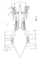
- FIG. 1 it is schematically represented a turbojet engine 1 comprising a high-pressure turbine 2, a low-pressure turbine 3, a combustion chamber 4, a high-pressure compressor 5, a fan 6
- the high pressure turbine 2 is equipped with distributors 8.
- an attachment device 20 for a turbine distributor 8 comprising fixed blades 10 distributed between an outer platform (not shown) and an inner platform 12. hooking flange 14 extends from this inner platform 12, being opposed to the fixed blades 10 relative to said inner platform 12.
- the distributor 8 is hooked on a support part, and this support part is itself fixed on a stabilizing part.
- the support part is a casing 22 of the injectors (not shown), and the stabilizing part is an extension 30 of a support of abradable material 18.
- the attachment device 20 implements a holding part 60 which contributes to the fixing of the stabilizing part 30 and the support part 22, and which contributes to the attachment of the distributor 8 to the support part 22 .
- the locking of the distributor 8 relative to the support part 22 is achieved by means of the attachment flange 14, which is locked in a locking groove 16 of the end 26 of the housing 22 of the injectors, by means of a locking pin 28.
- the dimensions of the locking groove 16 are adapted to the dimensions of the attachment flange 14, the flange of hooking 14 is pierced with a hooking hook hole (not visible in the figures), and the walls of the locking groove 16 are respectively pierced with wall holes 160 (see Figure 4).
- the locking pin 28 passes through said hooking flange hole and said wall holes.
- the blocking pin 28 is a stepped pin, so that it abuts against one of the walls of the blocking groove 16, which is the wall furthest downstream in FIG.
- the hooking flange 14, the locking groove 16, the locking pin 28 and the respective holes constitute locking means of the attachment device 20 according to the invention.
- the attachment device comprises interlocking means 44 of one end 26 of the housing 22 of the injectors with one end 30 of the extension 24 of the material support.
- abradable 18 retaining means 46, 48, 50, 52 to prevent relative rotation of the housing 22 relative to the extension 24, a holding member 60 to hold together the housing 22 and the extension 24, means of snap 34, 72 of the holding member 60 on the housing 22, and immobilizing means 76, 78, 80, 82 to prevent rotation of the holding member 60 relative to the housing 22. All these means will be described below.
- end 26 of the housing 22 will be called “end support 26"
- end 30 of the extension 24 will be called “stabilizing end 30”.
- the support end 26 is a piece of revolution about an axial direction which comprises an end body 36 from which the two walls delimiting the locking groove extend radially outwards. 16 described above.
- the end body 36 has a substantially rectangular axial section.
- the end body 36 has an inner face 38 located opposite the locking groove 16, an outer face 39 and a rear face 40 extending radially.
- the rearmost wall of the groove 16 has a flange 32 which extends rearwardly relative to the rear face 40 of the body 36. This flange 32 extends radially parallel to the direction opposite to the opening direction. of the groove 16. Between the flange 32 and the rear face 40 is formed a rear groove 42. On the free end of this flange 32 are cut teeth 34 which succeed each other over the entire periphery of the rim 32. These teeth 34 are directed radially inwards.
- the end body 36 has a recess 44 having a first facet 442 substantially parallel to the rear face 40 and a second facet 444 substantially perpendicular to said first facet 442.
- Grooves 46 are formed in said second facet 444, said grooves being oriented in the axial direction and substantially having a semicircular profile.
- FIG. 4 illustrates the interlocking between the support end 26 and the stabilizing end 30.
- the end of the stabilizing end 30 has a shape and dimensions that are complementary to those of the end recess 44.
- the stabilizing end 30 has a first face and a second face intended to come into contact respectively with said first facet 442 and second facet 444 of the support end 26.
- Grooves 48 are formed in said second face, said grooves 48 being oriented in the axial direction and substantially having a semicircular profile.
- the support end 26 and the stabilizing end 30 are interlocked with each other by a tenon and mortise type interlocking.
- This interlocking is achieved by an abutment of the respective first facet 442 and second facet 444 of the support end 26 with the respective first and second faces of the stabilizing end 30.
- the interlocking is made in such a way that the grooves 46 of the second facet 444 of the support end 26 come opposite the grooves 48 of the second face of the stabilizing end 30, so as to form, together, retaining orifices 50.
- Retaining pins 52 are introduced into said orifices retaining means to prevent said support end 26 and said stabilizing end 30 from rotating axially relative to each other.
- the interlocking means of the attachment device 20 comprise said recess 44 of the support end 26, as well as the complementary shapes and dimensions of the stabilizing end 30.
- the retaining means of the attachment device 20 comprise said grooves 46 of the support end 26, said grooves 48 of the stabilizing end 30 and said retaining orifices 50, as well as said retaining pins 52.
- the engagement between the support end 26 and the stabilizing end 30 is maintained by means of a holding piece 60, which is illustrated in FIG. 5.
- the holding piece 60 is an annular piece of revolution around an axial direction. It comprises a rectilinear central frame 62. This is extended at one end by a radiating portion 64 extending itself by an end portion 66 which returns to the central frame 62 and extends parallel thereto.
- the central framework 62, the radiating portion 64 and the end portion 66 define between them a holding groove 68, and said central framework 62 is extended at another end by a rectilinear flange 70 which is substantially perpendicular thereto and which overhangs said portion radially 64 and said end portion 66.
- the holding piece 60 has a section having substantially a shape of "J" whose vertical bar corresponds to the central frame 62 and whose horizontal bar corresponds to the flange 70 .
- the central framework 62 constitutes an elastically deformable zone of the holding part 60, which allows the establishment of the latter by an operator, as will be described later.
- teeth 72 On the free end of the end portion 66 are cut teeth 72 which succeed each other over the entire periphery of this end portion 66.
- the shape and the dimensions of the teeth 72 are complementary to the shape and dimensions of the teeth 34 of the flange 32 of the support end 26.
- the holding piece 60 also comprises a gripping flange 74 which extends from the central frame 62, on the opposite side to the holding groove 68 with respect to said central frame 62, and being slightly offset with respect to the flange 70.
- This gripping flange 74 comprises two successive zones which are angularly offset relative to each other and which facilitate the grip of this gripping flange 74 as well as the deformation of the central frame 62 by an operator.
- FIG. 6 illustrates, in radial section, maintaining the engagement of the two ends 26, 30 by means of the holding piece 60.
- the holding piece 60 has been snapped onto the support end 26, which is not shown only partially.
- the latching operation is performed in the following manner.
- the operator grasps the holding piece 60 by its gripping flange 74. It introduces the free end of the end portion 66 of the holding piece 60 into the rear groove 42 of the body 36 of the end 26, passing the complementary teeth 72 of the holding piece 60 between the teeth 34 of the flange 32. Simultaneously, the flange 32 of the support end 26 is introduced into the holding groove 68 of the holding piece 60. This introduction is facilitated by the presence of the elastic zone of the holding piece 60. The operator then releases the gripping flange 74. The central frame 62 of the holding piece 60 is then pressed against the flange 32 of the support end 26, and the flange 70 of the holding piece 60 is pressed against the outer face 39 of the support end 26.
- the latching thus obtained is of the bayonet lock type.
- the stabilizing end 30 is axially pressed against the first facet 442 of the support end 26 by the end portion 66 of the holding piece 60.
- the snap-fastening means of the attachment device 20 comprise the teeth 34 of the flange 32 of the support end 26 as well as the complementary teeth 72 of the holding piece 60.
- the attachment device 20 also comprises immobilization means intended to prevent reverse rotation of the holding member 60 with respect to the support end 26 which would lead to undesired setting of the latter.
- These immobilizing means comprise a slightly curved profile 76 of the central frame 62, the convexity of this slightly curved profile 76 being located on the side of the holding groove 68 (see FIG. 5).
- This slightly curved profile 76 causes an axial tension in the holding piece 60, which creates friction between said holding piece 60 and the rear face 40 of the support end 26, and prevents relative rotation of these two parts (see FIG. 6).
- FIGS. 3 and 5 Additional immobilizing means are illustrated in FIGS. 3 and 5. They comprise an immobilization hole 78 of the support end 26, pierced in one of the teeth 34 of the flange 32. They also comprise an immobilization hole 80 of the retaining piece 60, pierced in one of the complementary teeth 72. They finally comprise an immobilization pin 82 intended to be introduced into these two immobilization holes 78, 80 which for this purpose have substantially the same diameter .
- the immobilizing pin 82 is a stepped pin (see FIG. 3).
- the operator ensures that the two pierced teeth of these two immobilization holes 78, 80 are placed opposite each other and immobilizes the two snapped-in parts by introducing the pion d immobilization 82 in the two immobilization holes 78, 80 thus brought into coincidence.
Landscapes
- Engineering & Computer Science (AREA)
- Mechanical Engineering (AREA)
- General Engineering & Computer Science (AREA)
- Turbine Rotor Nozzle Sealing (AREA)
- Connection Of Plates (AREA)
- Snaps, Bayonet Connections, Set Pins, And Snap Rings (AREA)
- Structures Of Non-Positive Displacement Pumps (AREA)
Applications Claiming Priority (1)
| Application Number | Priority Date | Filing Date | Title |
|---|---|---|---|
| FR0654747A FR2908153B1 (fr) | 2006-11-07 | 2006-11-07 | Dispositif d'accrochage d'un distributeur (8) d'une turbine, turbine les comportant, et moteur d'aeronef en etant equipe |
Publications (2)
| Publication Number | Publication Date |
|---|---|
| EP1921273A1 true EP1921273A1 (de) | 2008-05-14 |
| EP1921273B1 EP1921273B1 (de) | 2009-10-07 |
Family
ID=38121758
Family Applications (1)
| Application Number | Title | Priority Date | Filing Date |
|---|---|---|---|
| EP07119994A Active EP1921273B1 (de) | 2006-11-07 | 2007-11-05 | Aufhängevorrichtung eines Turbinenleitkranzes |
Country Status (7)
| Country | Link |
|---|---|
| US (1) | US8182202B2 (de) |
| EP (1) | EP1921273B1 (de) |
| JP (1) | JP5209939B2 (de) |
| CA (1) | CA2608402C (de) |
| DE (1) | DE602007002684D1 (de) |
| FR (1) | FR2908153B1 (de) |
| RU (1) | RU2436965C2 (de) |
Cited By (4)
| Publication number | Priority date | Publication date | Assignee | Title |
|---|---|---|---|---|
| WO2011151592A1 (fr) * | 2010-06-02 | 2011-12-08 | Snecma | Palier de roulement pour turboréacteur d'aéronef équipé de moyens de rétention axiale de sa bague extérieure |
| US8419207B2 (en) | 2008-09-18 | 2013-04-16 | Golight Pty Limited | Portable light assembly |
| FR2981980A1 (fr) * | 2011-10-26 | 2013-05-03 | Snecma | Procede de montage d'un aubage fixe d'une turbomachine, carter et turbomachine comportant au moins un aubage fixe monte sur ce carter |
| FR3051014A1 (fr) * | 2016-05-09 | 2017-11-10 | Snecma | Ensemble pour turbomachine comprenant un distributeur, un element de structure de turbomachine, et un dispositif de fixation |
Families Citing this family (7)
| Publication number | Priority date | Publication date | Assignee | Title |
|---|---|---|---|---|
| DE102010007724A1 (de) * | 2010-02-12 | 2011-08-18 | Rolls-Royce Deutschland Ltd & Co KG, 15827 | Schraubenlose Zwischenstufendichtung einer Gasturbine |
| US9353767B2 (en) * | 2013-01-08 | 2016-05-31 | United Technologies Corporation | Stator anti-rotation device |
| FR3009740B1 (fr) | 2013-08-13 | 2017-12-15 | Snecma | Amelioration pour le verrouillage de pieces de support d'aubage |
| FR3053384B1 (fr) | 2016-06-30 | 2018-07-27 | Safran Aircraft Engines | Ensemble de fixation d'un distributeur a un element de structure d'une turbomachine |
| US10723884B2 (en) * | 2016-08-24 | 2020-07-28 | Toray Industries, Inc. | Black pigment, method for producing same, pigment dispersion liquid, photosensitive composition and cured product of said photosensitive composition |
| FR3066226B1 (fr) * | 2017-05-10 | 2020-07-17 | Safran Aircraft Engines | Verrouillage anneau stator sous distributeur haute pression |
| US11674400B2 (en) * | 2021-03-12 | 2023-06-13 | Ge Avio S.R.L. | Gas turbine engine nozzles |
Citations (3)
| Publication number | Priority date | Publication date | Assignee | Title |
|---|---|---|---|---|
| EP0513956A1 (de) * | 1991-05-13 | 1992-11-19 | General Electric Company | Bolzenlose Befestigung von einer Turbinendüse und einer Stationärgleitdichtung |
| US6095750A (en) * | 1998-12-21 | 2000-08-01 | General Electric Company | Turbine nozzle assembly |
| EP1369552A2 (de) * | 2002-06-06 | 2003-12-10 | General Electric Company | Schutzhaube für Flanschverbindungen in Gasturbinen |
Family Cites Families (15)
| Publication number | Priority date | Publication date | Assignee | Title |
|---|---|---|---|---|
| US3860359A (en) * | 1973-07-30 | 1975-01-14 | Curtiss Wright Corp | Mounting system for gas turbine power unit |
| US3989410A (en) * | 1974-11-27 | 1976-11-02 | General Electric Company | Labyrinth seal system |
| US4669959A (en) * | 1984-07-23 | 1987-06-02 | United Technologies Corporation | Breach lock anti-rotation key |
| RU1621622C (ru) * | 1989-02-06 | 1994-05-15 | Акционерное общество "Авиадвигатель" | Статор газовой турбины |
| FR2663997B1 (fr) * | 1990-06-27 | 1993-12-24 | Snecma | Dispositif de fixation d'une couronne de revolution sur un disque de turbomachine. |
| US5224822A (en) * | 1991-05-13 | 1993-07-06 | General Electric Company | Integral turbine nozzle support and discourager seal |
| US5271714A (en) * | 1992-07-09 | 1993-12-21 | General Electric Company | Turbine nozzle support arrangement |
| US5800124A (en) * | 1996-04-12 | 1998-09-01 | United Technologies Corporation | Cooled rotor assembly for a turbine engine |
| JP4432137B2 (ja) * | 1999-01-13 | 2010-03-17 | 株式会社Ihi | ジェットエンジン用ガスタービンのタービンノズル支持装置 |
| US6428272B1 (en) * | 2000-12-22 | 2002-08-06 | General Electric Company | Bolted joint for rotor disks and method of reducing thermal gradients therein |
| US6530744B2 (en) * | 2001-05-29 | 2003-03-11 | General Electric Company | Integral nozzle and shroud |
| US6742987B2 (en) * | 2002-07-16 | 2004-06-01 | General Electric Company | Cradle mounted turbine nozzle |
| JP4072683B2 (ja) * | 2003-08-19 | 2008-04-09 | 豊和工業株式会社 | 旋回式クランプシリンダ |
| RU2260700C2 (ru) * | 2003-11-24 | 2005-09-20 | Открытое акционерное общество "Авиадвигатель" | Сопловой аппарат турбины газотурбинного двигателя |
| FR2867223B1 (fr) * | 2004-03-03 | 2006-07-28 | Snecma Moteurs | Turbomachine comme par exemple un turboreacteur pour avion |
-
2006
- 2006-11-07 FR FR0654747A patent/FR2908153B1/fr active Active
-
2007
- 2007-10-30 CA CA2608402A patent/CA2608402C/fr active Active
- 2007-11-05 DE DE602007002684T patent/DE602007002684D1/de active Active
- 2007-11-05 EP EP07119994A patent/EP1921273B1/de active Active
- 2007-11-06 US US11/935,570 patent/US8182202B2/en active Active
- 2007-11-06 JP JP2007288137A patent/JP5209939B2/ja active Active
- 2007-11-06 RU RU2007141150/06A patent/RU2436965C2/ru active
Patent Citations (3)
| Publication number | Priority date | Publication date | Assignee | Title |
|---|---|---|---|---|
| EP0513956A1 (de) * | 1991-05-13 | 1992-11-19 | General Electric Company | Bolzenlose Befestigung von einer Turbinendüse und einer Stationärgleitdichtung |
| US6095750A (en) * | 1998-12-21 | 2000-08-01 | General Electric Company | Turbine nozzle assembly |
| EP1369552A2 (de) * | 2002-06-06 | 2003-12-10 | General Electric Company | Schutzhaube für Flanschverbindungen in Gasturbinen |
Cited By (11)
| Publication number | Priority date | Publication date | Assignee | Title |
|---|---|---|---|---|
| US8419207B2 (en) | 2008-09-18 | 2013-04-16 | Golight Pty Limited | Portable light assembly |
| WO2011151592A1 (fr) * | 2010-06-02 | 2011-12-08 | Snecma | Palier de roulement pour turboréacteur d'aéronef équipé de moyens de rétention axiale de sa bague extérieure |
| FR2960907A1 (fr) * | 2010-06-02 | 2011-12-09 | Snecma | Palier de roulement pour turboreacteur d'aeronef equipe de moyens ameliores de retention axiale de sa bague exterieure |
| US9341079B2 (en) | 2010-06-02 | 2016-05-17 | Snecma | Rolling bearing for aircraft turbojet fitted with improved means of axial retention of its outer ring |
| FR2981980A1 (fr) * | 2011-10-26 | 2013-05-03 | Snecma | Procede de montage d'un aubage fixe d'une turbomachine, carter et turbomachine comportant au moins un aubage fixe monte sur ce carter |
| US9366150B2 (en) | 2011-10-26 | 2016-06-14 | Snecma | Method for mounting a stator blading of a turbomachine, an engine casing and a turbomachine comprising at least one stator blading mounted on this engine casing |
| FR3051014A1 (fr) * | 2016-05-09 | 2017-11-10 | Snecma | Ensemble pour turbomachine comprenant un distributeur, un element de structure de turbomachine, et un dispositif de fixation |
| WO2017194865A1 (fr) * | 2016-05-09 | 2017-11-16 | Safran Aircraft Engines | Ensemble pour turbomachine comprenant un distributeur, un élément de structure de turbomachine, et un dispositif de fixation |
| CN109072706A (zh) * | 2016-05-09 | 2018-12-21 | 赛峰航空器发动机 | 用于包括分配器、涡轮机的结构元件和连接装置的涡轮机的组件 |
| US10941668B2 (en) | 2016-05-09 | 2021-03-09 | Safran Aircraft Engines | Assembly for a turbomachine comprising a distributor, a structural element of the turbomachine, and an attachment device |
| CN109072706B (zh) * | 2016-05-09 | 2021-06-08 | 赛峰航空器发动机 | 用于包括分配器、涡轮机的结构元件和连接装置的涡轮机的组件 |
Also Published As
| Publication number | Publication date |
|---|---|
| EP1921273B1 (de) | 2009-10-07 |
| US8182202B2 (en) | 2012-05-22 |
| JP5209939B2 (ja) | 2013-06-12 |
| CA2608402C (fr) | 2014-10-21 |
| FR2908153A1 (fr) | 2008-05-09 |
| RU2436965C2 (ru) | 2011-12-20 |
| JP2008138670A (ja) | 2008-06-19 |
| RU2007141150A (ru) | 2009-05-20 |
| US20080107530A1 (en) | 2008-05-08 |
| FR2908153B1 (fr) | 2011-05-13 |
| DE602007002684D1 (de) | 2009-11-19 |
| CA2608402A1 (fr) | 2008-05-07 |
Similar Documents
| Publication | Publication Date | Title |
|---|---|---|
| EP1921273B1 (de) | Aufhängevorrichtung eines Turbinenleitkranzes | |
| EP2839117B1 (de) | Turbinenstufe für eine turbomaschine | |
| EP3074639B1 (de) | Gebläse, insbesondere für eine turbomaschine, sowie flansch dafür | |
| FR2485117A1 (de) | ||
| EP2925993B1 (de) | Turbinenmotorhaube zum abdecken eines lüfterkonus | |
| EP3033495B1 (de) | Verbesserung an der verriegelung von klingentragekomponenten | |
| FR3057908A1 (fr) | Ensemble rotatif d'une turbomachine muni d'un systeme de maintien axial d'une aube | |
| WO2013182797A1 (fr) | Turbomachine comportant des moyens de fixation amont d'un tube de deshuilage | |
| FR3018773A1 (fr) | Dispositif de support | |
| EP3455466B1 (de) | Anordnung für turbomaschine mit einem verteiler, strukturelles element einer turbomaschine und anbauvorrichtung | |
| CA2364128A1 (fr) | Systeme de retention des abes de type combine ou cascade | |
| EP2060744B1 (de) | Turbinen- oder Kompressorstufe eines Turbotriebwerks | |
| FR3015579A1 (fr) | Nez d'injecteur comprenant une semelle de maitien logee dans une partie fixe de systeme d'injection | |
| FR2671140A1 (fr) | Aubage redresseur pour compresseur de turbomachine. | |
| FR3015638A1 (fr) | Segment d'obturation de traversee coulissante de systeme d'injection pour turbomachine | |
| EP1890030B1 (de) | Schnellkupplung | |
| WO2018002480A1 (fr) | Ensemble de fixation d'un distributeur a un element de structure d'une turbomachine | |
| FR2968369A1 (fr) | Dispositif de cage pour un ecrou susceptible d'etre visse sur une vis | |
| EP1603760B1 (de) | Montagevorrichtung einer drehbaren anordnung auf einer achse | |
| FR3085994A1 (fr) | Anneau de retention axiale d'aubes pour roue mobile de turbomachine, de preference pour aeronef | |
| FR2766885A1 (fr) | Dispositif de commande d'embrayage | |
| EP0870942B1 (de) | Kupplungsausrücklager mit einer Anti-Verschleiss-Platte | |
| EP3931427B1 (de) | Anordnung für eine turbine einer turbomaschine | |
| FR3142780A1 (fr) | Système de bridage d'aube d'une soufflante muni d'une pince déformable et d'un organe de serrage associé | |
| FR3015641A1 (fr) | Dispositif d'injection dans une turbomachine |
Legal Events
| Date | Code | Title | Description |
|---|---|---|---|
| PUAI | Public reference made under article 153(3) epc to a published international application that has entered the european phase |
Free format text: ORIGINAL CODE: 0009012 |
|
| 17P | Request for examination filed |
Effective date: 20071105 |
|
| AK | Designated contracting states |
Kind code of ref document: A1 Designated state(s): AT BE BG CH CY CZ DE DK EE ES FI FR GB GR HU IE IS IT LI LT LU LV MC MT NL PL PT RO SE SI SK TR |
|
| AX | Request for extension of the european patent |
Extension state: AL BA HR MK RS |
|
| AKX | Designation fees paid |
Designated state(s): DE FR GB |
|
| GRAP | Despatch of communication of intention to grant a patent |
Free format text: ORIGINAL CODE: EPIDOSNIGR1 |
|
| RTI1 | Title (correction) |
Free format text: DEVICE FOR ATTACHING A TURBINE NOZZLE |
|
| RIN1 | Information on inventor provided before grant (corrected) |
Inventor name: BART JACQUES Inventor name: ROUSSELIN, STEPHANE Inventor name: ESCURE, DIDIER |
|
| GRAS | Grant fee paid |
Free format text: ORIGINAL CODE: EPIDOSNIGR3 |
|
| GRAA | (expected) grant |
Free format text: ORIGINAL CODE: 0009210 |
|
| AK | Designated contracting states |
Kind code of ref document: B1 Designated state(s): DE FR GB |
|
| REG | Reference to a national code |
Ref country code: GB Ref legal event code: FG4D Free format text: NOT ENGLISH |
|
| REF | Corresponds to: |
Ref document number: 602007002684 Country of ref document: DE Date of ref document: 20091119 Kind code of ref document: P |
|
| PLBE | No opposition filed within time limit |
Free format text: ORIGINAL CODE: 0009261 |
|
| STAA | Information on the status of an ep patent application or granted ep patent |
Free format text: STATUS: NO OPPOSITION FILED WITHIN TIME LIMIT |
|
| 26N | No opposition filed |
Effective date: 20100708 |
|
| REG | Reference to a national code |
Ref country code: FR Ref legal event code: PLFP Year of fee payment: 9 |
|
| REG | Reference to a national code |
Ref country code: FR Ref legal event code: PLFP Year of fee payment: 10 |
|
| REG | Reference to a national code |
Ref country code: FR Ref legal event code: PLFP Year of fee payment: 11 |
|
| REG | Reference to a national code |
Ref country code: FR Ref legal event code: CD Owner name: SAFRAN AIRCRAFT ENGINES, FR Effective date: 20170719 |
|
| REG | Reference to a national code |
Ref country code: FR Ref legal event code: PLFP Year of fee payment: 12 |
|
| PGFP | Annual fee paid to national office [announced via postgrant information from national office to epo] |
Ref country code: DE Payment date: 20251118 Year of fee payment: 19 |
|
| PGFP | Annual fee paid to national office [announced via postgrant information from national office to epo] |
Ref country code: GB Payment date: 20251125 Year of fee payment: 19 |
|
| PGFP | Annual fee paid to national office [announced via postgrant information from national office to epo] |
Ref country code: FR Payment date: 20251125 Year of fee payment: 19 |