EP1921320B1 - Spiralverdichter mit Dampfzufuhr und Entladungsanschluss - Google Patents
Spiralverdichter mit Dampfzufuhr und Entladungsanschluss Download PDFInfo
- Publication number
- EP1921320B1 EP1921320B1 EP07254203A EP07254203A EP1921320B1 EP 1921320 B1 EP1921320 B1 EP 1921320B1 EP 07254203 A EP07254203 A EP 07254203A EP 07254203 A EP07254203 A EP 07254203A EP 1921320 B1 EP1921320 B1 EP 1921320B1
- Authority
- EP
- European Patent Office
- Prior art keywords
- unloader
- economizer
- port
- line
- refrigerant
- Prior art date
- Legal status (The legal status is an assumption and is not a legal conclusion. Google has not performed a legal analysis and makes no representation as to the accuracy of the status listed.)
- Not-in-force
Links
- 238000002347 injection Methods 0.000 title claims description 25
- 239000007924 injection Substances 0.000 title claims description 25
- 239000003507 refrigerant Substances 0.000 claims description 40
- 238000007906 compression Methods 0.000 claims description 27
- 230000006835 compression Effects 0.000 claims description 26
- 235000014676 Phragmites communis Nutrition 0.000 description 3
- 238000000034 method Methods 0.000 description 3
- 238000001816 cooling Methods 0.000 description 2
- 238000010276 construction Methods 0.000 description 1
- 230000009977 dual effect Effects 0.000 description 1
- 239000007788 liquid Substances 0.000 description 1
- 238000012986 modification Methods 0.000 description 1
- 230000004048 modification Effects 0.000 description 1
- 230000003071 parasitic effect Effects 0.000 description 1
Images

Classifications
-
- F—MECHANICAL ENGINEERING; LIGHTING; HEATING; WEAPONS; BLASTING
- F04—POSITIVE - DISPLACEMENT MACHINES FOR LIQUIDS; PUMPS FOR LIQUIDS OR ELASTIC FLUIDS
- F04C—ROTARY-PISTON, OR OSCILLATING-PISTON, POSITIVE-DISPLACEMENT MACHINES FOR LIQUIDS; ROTARY-PISTON, OR OSCILLATING-PISTON, POSITIVE-DISPLACEMENT PUMPS
- F04C28/00—Control of, monitoring of, or safety arrangements for, pumps or pumping installations specially adapted for elastic fluids
- F04C28/24—Control of, monitoring of, or safety arrangements for, pumps or pumping installations specially adapted for elastic fluids characterised by using valves controlling pressure or flow rate, e.g. discharge valves or unloading valves
- F04C28/26—Control of, monitoring of, or safety arrangements for, pumps or pumping installations specially adapted for elastic fluids characterised by using valves controlling pressure or flow rate, e.g. discharge valves or unloading valves using bypass channels
-
- F—MECHANICAL ENGINEERING; LIGHTING; HEATING; WEAPONS; BLASTING
- F04—POSITIVE - DISPLACEMENT MACHINES FOR LIQUIDS; PUMPS FOR LIQUIDS OR ELASTIC FLUIDS
- F04C—ROTARY-PISTON, OR OSCILLATING-PISTON, POSITIVE-DISPLACEMENT MACHINES FOR LIQUIDS; ROTARY-PISTON, OR OSCILLATING-PISTON, POSITIVE-DISPLACEMENT PUMPS
- F04C18/00—Rotary-piston pumps specially adapted for elastic fluids
- F04C18/02—Rotary-piston pumps specially adapted for elastic fluids of arcuate-engagement type, i.e. with circular translatory movement of co-operating members, each member having the same number of teeth or tooth-equivalents
-
- F—MECHANICAL ENGINEERING; LIGHTING; HEATING; WEAPONS; BLASTING
- F04—POSITIVE - DISPLACEMENT MACHINES FOR LIQUIDS; PUMPS FOR LIQUIDS OR ELASTIC FLUIDS
- F04C—ROTARY-PISTON, OR OSCILLATING-PISTON, POSITIVE-DISPLACEMENT MACHINES FOR LIQUIDS; ROTARY-PISTON, OR OSCILLATING-PISTON, POSITIVE-DISPLACEMENT PUMPS
- F04C29/00—Component parts, details or accessories of pumps or pumping installations, not provided for in groups F04C18/00 - F04C28/00
- F04C29/12—Arrangements for admission or discharge of the working fluid, e.g. constructional features of the inlet or outlet
- F04C29/124—Arrangements for admission or discharge of the working fluid, e.g. constructional features of the inlet or outlet with inlet and outlet valves specially adapted for rotary or oscillating piston pumps
- F04C29/126—Arrangements for admission or discharge of the working fluid, e.g. constructional features of the inlet or outlet with inlet and outlet valves specially adapted for rotary or oscillating piston pumps of the non-return type
- F04C29/128—Arrangements for admission or discharge of the working fluid, e.g. constructional features of the inlet or outlet with inlet and outlet valves specially adapted for rotary or oscillating piston pumps of the non-return type of the elastic type, e.g. reed valves
-
- F—MECHANICAL ENGINEERING; LIGHTING; HEATING; WEAPONS; BLASTING
- F04—POSITIVE - DISPLACEMENT MACHINES FOR LIQUIDS; PUMPS FOR LIQUIDS OR ELASTIC FLUIDS
- F04C—ROTARY-PISTON, OR OSCILLATING-PISTON, POSITIVE-DISPLACEMENT MACHINES FOR LIQUIDS; ROTARY-PISTON, OR OSCILLATING-PISTON, POSITIVE-DISPLACEMENT PUMPS
- F04C18/00—Rotary-piston pumps specially adapted for elastic fluids
- F04C18/02—Rotary-piston pumps specially adapted for elastic fluids of arcuate-engagement type, i.e. with circular translatory movement of co-operating members, each member having the same number of teeth or tooth-equivalents
- F04C18/0207—Rotary-piston pumps specially adapted for elastic fluids of arcuate-engagement type, i.e. with circular translatory movement of co-operating members, each member having the same number of teeth or tooth-equivalents both members having co-operating elements in spiral form
- F04C18/0215—Rotary-piston pumps specially adapted for elastic fluids of arcuate-engagement type, i.e. with circular translatory movement of co-operating members, each member having the same number of teeth or tooth-equivalents both members having co-operating elements in spiral form where only one member is moving
-
- F—MECHANICAL ENGINEERING; LIGHTING; HEATING; WEAPONS; BLASTING
- F04—POSITIVE - DISPLACEMENT MACHINES FOR LIQUIDS; PUMPS FOR LIQUIDS OR ELASTIC FLUIDS
- F04C—ROTARY-PISTON, OR OSCILLATING-PISTON, POSITIVE-DISPLACEMENT MACHINES FOR LIQUIDS; ROTARY-PISTON, OR OSCILLATING-PISTON, POSITIVE-DISPLACEMENT PUMPS
- F04C23/00—Combinations of two or more pumps, each being of rotary-piston or oscillating-piston type, specially adapted for elastic fluids; Pumping installations specially adapted for elastic fluids; Multi-stage pumps specially adapted for elastic fluids
- F04C23/008—Hermetic pumps
Definitions
- This application relates to a scroll compressor wherein one set of ports is utilized for both injecting vapor refrigerant into the compressor and for compressor unloading by directing vapor refrigerant from the compressor intermediate compression point to compressor suction, and wherein the other separate set of ports is utilized only for compressor unloading.
- first and second scroll members each have a base and a generally spiral wrap extending from the base.
- the wraps of the two scroll members interfit to define compression chambers.
- One of the two scroll members is caused to orbit relative to the other, and as they orbit relative to each other, refrigerant is trapped within compression chambers defined between the wraps.
- the size of these compression chambers is reduced and the entrapped refrigerant is compressed.
- the compressor when there is a reduced cooling capacity desired from a refrigerant system associated with the scroll compressor, the compressor may be "unloaded". When the compressor is unloaded, refrigerant may be tapped from the compression chambers through an open unloader valve and back to a suction port leading into the compressor. In this manner, the amount of compressed refrigerant is reduced, and the capacity of the associated refrigerant system is similarly reduced.
- an economizer cycle may be actuated.
- refrigerant downstream of a condenser is tapped from a main refrigerant flow line and the tapped refrigerant is expanded.
- the tapped refrigerant passes in a heat transfer relationship with the main refrigerant line in an economizer heat exchanger, thereby sub-cooling the main refrigerant flow.
- the tapped refrigerant is injected into an intermediate compression port or set of ports in the compressor.
- the economizer injection passage is also connected to the unloader line which selectively communicates the economizer injection passage back to the suction line.
- the economizer injection passage can be kept open or shutoff, with the shut off device installed in the economizer line between the condenser and the unloader line.
- Separate flow control devices control the operation of both the economizer function and the unloader.
- EP 1158167 (Daikin Ind. Ltd), considered to represent the closest prior art, discloses a scroll compressor and air conditioner.
- the unloader port and the economizer port are distinct.
- the unloader line is not connected to the injection line.
- US 2004/184932 discloses an apparatus and method for injecting a liquid vapour into compression chambers at an intermediate pressure.
- a single passage communicates through a compressor shell, and into a passage in non-orbiting scroll member.
- the passage leads to both economizer ports, and bypass ports which extend through a base of the non-orbiting scroll member to communicate with the compression chambers.
- the economizer ports are preferably positioned more adjacent a mid-way portion of the compression cycle (however under some circumstances it might be more desirable to position them closer to the suction side), while the separate bypass holes are positioned closer to the suction side.
- the bypass holes are preferably of a larger cross-sectional area than the economizer holes.
- bypass holes are preferably associated with the check valve such that the vapor being injected into the economizer injection holes does not pass into the bypass holes.
- the by-pass flow can pass through an injection port and by-pass dedicated port (when the flow is by-passed the check valve is open). In this case the by-pass process is further optimized because the amount of by-pass flow is further increased as the by-pass flow can pass through both of these openings.
- the scroll compressor designers can design the size and location of the ports to be optimum for each function.
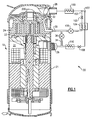
- a refrigerant system 20 is illustrated in Figure 1 having a compressor 19 with a compressor shell 21.
- the compressor is a scroll compressor having an orbiting scroll member 22 and a non-orbiting scroll member 24.
- a suction line 26 delivers a refrigerant into a chamber 31 within the compressor shell 21.
- refrigerant is compressed between the orbiting scroll member 22 and non-orbiting scroll member 24, and delivered outwardly of the shell 21 through a discharge line 28.
- An economizer injection line 30 communicates with a passage 32 extending through a base of the non-orbiting scroll member 24.
- a line 34 communicates the passage 30 back to the suction line 26.
- An unloader valve 36 positioned on this line 34 selectively blocks or allows refrigerant to flow from the compression chamber outwardly and back into the suction line 26.
- a condenser 100 is positioned downstream of discharge port 28.
- a tap 102 taps a portion of a refrigerant from a main refrigerant line 103, and expands that tapped refrigerant in an expansion device 105.
- the tapped refrigerant passes in heat transfer relationship with the refrigerant in the main flow line 103 in an economizer heat exchanger 104.
- the tapped refrigerant is returned back through a valve 106 and into the line through the passage 30. While the flow of the tapped refrigerant 102 and main refrigerant flow 103 are shown in the same direction through the economizer heat exchanger 104, in practice they may be in counter-flow directions.
- the main refrigerant flow line Downstream of the economizer heat exchanger 104, the main refrigerant flow line passes through an expansion device 108, an evaporator 110, and back to the suction line 26.
- the passage 32 communicates with economizer injection ports 200.
- economizer injection ports 200 there are can be a pair (or multiple ports) of ports 200 or a single port associated with two distinct locations in the base of the non-orbiting scroll 24.
- unloader ports 202 are shown in this figure. As shown in this Figure, the locations of the ports 202 are closer to the outer portions of the wraps of the orbiting and non-orbiting scroll members, and thus closer to a suction location than are the economizer holes 200.
- the by-pass unloader ports can be exposed to both chamber 31 at suction pressure as well as partially compressed gas between the fixed scroll 24 and orbiting scroll 22. If the by-pass unloader ports are positioned further into the compression process, they may be only exposed to the partially compressed refrigerant and be essentially isolated form the chamber 31.
- the unloader holes 202 are associated with a valve stop 204, bolt 210 holding the valve stop 204, and a reed valve 206.
- the pressure inside the scroll elements is higher then the suction pressure, which opens the reed valve and permits a portion of the flow from the scroll compression pockets to by-pass back to suction through passages 202.
- Some additional flow is also by-passed through open passages 200, which are always open.
- pressure in the economized passage is higher then pressure inside the scroll compression pockets, thus the reed valve is closed preventing vapor injection from being injected through the blocked off passages 202.
- the vapor is then only injected through passages 200, whose size and location is specifically selected to optimize the amount of vapor-injected flow.
- the present invention is able to provide an optimum design for these types of operation.
- the prior art compromises as set forth above are thus eliminated.
Landscapes
- Engineering & Computer Science (AREA)
- Mechanical Engineering (AREA)
- General Engineering & Computer Science (AREA)
- Physics & Mathematics (AREA)
- Fluid Mechanics (AREA)
- Rotary Pumps (AREA)
Claims (9)
- Spiralverdichter (19), der aufweist:ein erstes Spiralelement (24) mit einer Basis und einer sich aus seiner Basis erstreckenden im Allgemeinen spiralförmigen Windung;ein zweites Spiralelement (22) mit einer Basis und einer sich aus seiner Basis erstreckenden im Allgemeinen spiralförmigen Windung, wobei die Basis des ersten und des zweiten Spiralelementes (24, 22) passen, um Verdichtungskammern zu definieren, wobei das zweite Spiralelement (22) angetrieben wird, um relativ zum ersten Spiralelement (24) zu kreisen;eine Saugleitung (26) für das Übertragen von Kältemittel in ein Verdichtergehäuse (21) für den Verdichter (19) und eine Austrittsleitung (28) für ein Übertragen des Kältemittels nach außerhalb des Gehäuses (21);eine Economizer-Einspritzleitung (30) für das Einspritzen eines Kältemitteldampfes zurück in die Verdichtungskammern aus einem Economizer-Kreislauf, wobei die Economizer-Einspritzleitung (30) durch die Basis des ersten Spiralelementes (24) gelangt und mit mindestens einer Economizer-Öffnung (200) für das Einspritzen des Kältemitteldampfes in die Verdichtungskammern in Verbindung steht; undeine Entladungsleitung (34) für das selektive Verbinden der Economizer-Einspritzleitung (30) zurück zur Saugleitung (26), wobei die Entladungsleitung (34) mit einem Entladungsventil (36) verbunden ist, und wobei mindestens eine Entladungsöffnung (202) in der nichtkreisenden Spirale (22) vorhanden ist und, wenn das Entladungsventil (36) geöffnet ist, um das Kältemittel aus den Verdichtungskammern durch die Entladungsöffnung (202) in die Economizer-Einspritzleitung (30), in die Entladungsleitung (34) und zur Saugleitung (26) zu übertragen, wobei die Entladungsöffnung (202) und die Economizer-Öffnung (200) getrennte Öffnungen sind.
- Spiralverdichter (19) nach Anspruch 1, bei dem die Economizer-Öffnung (200) weiter in einem Verdichtungszyklus positioniert ist als die Entladungsöffnung (202).
- Spiralverdichter (19) nach Anspruch 2, bei dem zwei Entladungsöffnungen (202) und zwei Economizer-Öffnungen (200) vorhanden sind.
- Spiralverdichter (19) nach einem der vorhergehenden Ansprüche, bei dem ein Regulierventil (106) den Fluss von der Economizer-Einspritzleitung (30) in die Verdichtungskammern durch die Entladungsöffnung (202) absperrt, wobei sich das Regulierventil (106) öffnet, um den Fluss des Kältemittels von den Verdichtungskammern durch die Entladungsöffnung (202) und in die Economizer-Einspritzleitung (30) zu gestatten.
- Spiralverdichter (19) nach einem der vorhergehenden Ansprüche, bei dem mindestens eine Economizer-Öffnung (200) eine kleinere Querschnittsfläche aufweist als mindestens eine Entladungsöffnung (202).
- Spiralverdichter (19) nach einem der vorhergehenden Ansprüche, bei dem der Strömungswiderstand von mindestens einer der Economizer-Öffnungen (200) größer ist als der Strömungswiderstand von mindestens einer der Entladungsöffnungen (202).
- Spiralverdichter (19) nach einem der vorhergehenden Ansprüche, bei dem, wenn das Entladungsventil (36) offen ist, Kältemittel ebenfalls durch die Economizer-Öffnung (200) in die Economizer-Einspritzleitung (30), die Entladungsleitung (34) und zur Saugleitung (26) gelangen kann.
- Spiralverdichter (19) nach Anspruch 1, bei dem
die Economizer-Öffnung (200) weiter in einem Verdichtungszyklus positioniert ist als die Entladungsöffnung (202), und wobei die mindestens eine Economizer-Öffnung (200) eine kleinere Querschnittsfläche aufweist als die mindestens eine Entladungsöffnung (202); und wobei der Spiralverdichter (19) außerdem aufweist:ein Regulierventil (106), das den Fluss von der Economizer-Einspritzleitung (30) in die Verdichtungskammern durch die Entladungsöffnung (202) absperrt, wobei das Öffnen des Regulierventils (106) den Fluss des Kältemittels von den Verdichtungskammern durch die Entladungsöffnung (202) und in die Economizer-Einspritzleitung (30) gestattet. - Spiralverdichter (19) nach Anspruch 8, bei dem, wenn das Entladungsventil (36) offen ist, Kältemittel ebenfalls durch die Economizer-Öffnung (200) in die Economizer-Einspritzleitung (30), die Entladungsleitung (34) und zur Saugleitung (26) gelangen kann.
Applications Claiming Priority (1)
| Application Number | Priority Date | Filing Date | Title |
|---|---|---|---|
| US11/593,732 US7674098B2 (en) | 2006-11-07 | 2006-11-07 | Scroll compressor with vapor injection and unloader port |
Publications (3)
| Publication Number | Publication Date |
|---|---|
| EP1921320A2 EP1921320A2 (de) | 2008-05-14 |
| EP1921320A3 EP1921320A3 (de) | 2011-07-27 |
| EP1921320B1 true EP1921320B1 (de) | 2012-10-17 |
Family
ID=39047170
Family Applications (1)
| Application Number | Title | Priority Date | Filing Date |
|---|---|---|---|
| EP07254203A Not-in-force EP1921320B1 (de) | 2006-11-07 | 2007-10-23 | Spiralverdichter mit Dampfzufuhr und Entladungsanschluss |
Country Status (5)
| Country | Link |
|---|---|
| US (1) | US7674098B2 (de) |
| EP (1) | EP1921320B1 (de) |
| JP (1) | JP2008115865A (de) |
| KR (1) | KR20080041565A (de) |
| CN (1) | CN101178065B (de) |
Families Citing this family (31)
| Publication number | Priority date | Publication date | Assignee | Title |
|---|---|---|---|---|
| US7815423B2 (en) * | 2005-07-29 | 2010-10-19 | Emerson Climate Technologies, Inc. | Compressor with fluid injection system |
| EP2307728B1 (de) | 2008-05-30 | 2016-08-10 | Emerson Climate Technologies, Inc. | Verdichter mit einer kolbenbetätigung umfassenden anordnung zur liefermengeneinstellung |
| US8303278B2 (en) * | 2008-07-08 | 2012-11-06 | Tecumseh Products Company | Scroll compressor utilizing liquid or vapor injection |
| FR2940373B1 (fr) * | 2008-12-19 | 2014-07-04 | Danfoss Commercial Compressors | Compresseur frigorifique a spirales |
| KR101056882B1 (ko) * | 2009-01-07 | 2011-08-12 | 엘지전자 주식회사 | 스크롤 압축기 |
| US7988433B2 (en) | 2009-04-07 | 2011-08-02 | Emerson Climate Technologies, Inc. | Compressor having capacity modulation assembly |
| US8616014B2 (en) * | 2009-05-29 | 2013-12-31 | Emerson Climate Technologies, Inc. | Compressor having capacity modulation or fluid injection systems |
| US8303279B2 (en) * | 2009-09-08 | 2012-11-06 | Danfoss Scroll Technologies, Llc | Injection tubes for injection of fluid into a scroll compressor |
| CN103452840A (zh) * | 2013-09-12 | 2013-12-18 | 安徽奥特佳科技发展有限公司 | 双级压缩中间喷射的汽车热泵电动涡旋压缩机 |
| CN105874204B (zh) * | 2014-01-22 | 2018-06-01 | 三菱电机株式会社 | 涡旋压缩机 |
| US9850903B2 (en) | 2014-12-09 | 2017-12-26 | Emerson Climate Technologies, Inc. | Capacity modulated scroll compressor |
| KR101747175B1 (ko) * | 2016-02-24 | 2017-06-14 | 엘지전자 주식회사 | 스크롤 압축기 |
| KR101800261B1 (ko) | 2016-05-25 | 2017-11-22 | 엘지전자 주식회사 | 스크롤 압축기 |
| KR101839886B1 (ko) | 2016-05-30 | 2018-03-19 | 엘지전자 주식회사 | 스크롤 압축기 |
| CN109891097B (zh) | 2016-06-02 | 2020-04-21 | 特灵国际有限公司 | 具有部分负载容量的涡旋压缩机 |
| DE102017115623A1 (de) * | 2016-07-13 | 2018-01-18 | Trane International Inc. | Variable Economizereinspritzposition |
| CN108626117B (zh) * | 2017-03-23 | 2020-05-19 | 艾默生环境优化技术(苏州)有限公司 | 双圈涡旋压缩组件及涡旋压缩机 |
| KR102332212B1 (ko) * | 2017-06-22 | 2021-11-29 | 엘지전자 주식회사 | 스크롤 압축기 및 이를 구비한 공기 조화기 |
| US10995753B2 (en) | 2018-05-17 | 2021-05-04 | Emerson Climate Technologies, Inc. | Compressor having capacity modulation assembly |
| CN111502987B (zh) * | 2019-01-30 | 2022-06-28 | 艾默生环境优化技术(苏州)有限公司 | 容量调节和喷气增焓一体式涡旋压缩机及其系统 |
| US11656003B2 (en) | 2019-03-11 | 2023-05-23 | Emerson Climate Technologies, Inc. | Climate-control system having valve assembly |
| KR20210042690A (ko) * | 2019-10-10 | 2021-04-20 | 엘지전자 주식회사 | 전동식 압축기 |
| US11560889B1 (en) * | 2021-06-30 | 2023-01-24 | Trane International Inc. | Scroll compressor with second intermediate cap to facilitate refrigerant injection |
| US11655813B2 (en) | 2021-07-29 | 2023-05-23 | Emerson Climate Technologies, Inc. | Compressor modulation system with multi-way valve |
| US12259163B2 (en) | 2022-06-01 | 2025-03-25 | Copeland Lp | Climate-control system with thermal storage |
| US11846287B1 (en) | 2022-08-11 | 2023-12-19 | Copeland Lp | Scroll compressor with center hub |
| US12313072B2 (en) * | 2022-11-30 | 2025-05-27 | Trane International Inc. | Oil-free phase separating compressor |
| US11965507B1 (en) | 2022-12-15 | 2024-04-23 | Copeland Lp | Compressor and valve assembly |
| US12416308B2 (en) | 2022-12-28 | 2025-09-16 | Copeland Lp | Compressor with shutdown assembly |
| US12173708B1 (en) | 2023-12-07 | 2024-12-24 | Copeland Lp | Heat pump systems with capacity modulation |
| US12163523B1 (en) | 2023-12-15 | 2024-12-10 | Copeland Lp | Compressor and valve assembly |
Family Cites Families (9)
| Publication number | Priority date | Publication date | Assignee | Title |
|---|---|---|---|---|
| US6042344A (en) * | 1998-07-13 | 2000-03-28 | Carrier Corporation | Control of scroll compressor at shutdown to prevent unpowered reverse rotation |
| JP4639413B2 (ja) * | 1999-12-06 | 2011-02-23 | ダイキン工業株式会社 | スクロール圧縮機および空気調和機 |
| US6457948B1 (en) * | 2001-04-25 | 2002-10-01 | Copeland Corporation | Diagnostic system for a compressor |
| US6474087B1 (en) * | 2001-10-03 | 2002-11-05 | Carrier Corporation | Method and apparatus for the control of economizer circuit flow for optimum performance |
| US6571576B1 (en) * | 2002-04-04 | 2003-06-03 | Carrier Corporation | Injection of liquid and vapor refrigerant through economizer ports |
| US7100386B2 (en) * | 2003-03-17 | 2006-09-05 | Scroll Technologies | Economizer/by-pass port inserts to control port size |
| KR100557057B1 (ko) * | 2003-07-26 | 2006-03-03 | 엘지전자 주식회사 | 용량 조절식 스크롤 압축기 |
| US7278832B2 (en) * | 2004-01-07 | 2007-10-09 | Carrier Corporation | Scroll compressor with enlarged vapor injection port area |
| US7228710B2 (en) * | 2005-05-31 | 2007-06-12 | Scroll Technologies | Indentation to optimize vapor injection through ports extending through scroll wrap |
-
2006
- 2006-11-07 US US11/593,732 patent/US7674098B2/en active Active
-
2007
- 2007-10-04 KR KR1020070099589A patent/KR20080041565A/ko not_active Withdrawn
- 2007-10-23 EP EP07254203A patent/EP1921320B1/de not_active Not-in-force
- 2007-11-05 JP JP2007287177A patent/JP2008115865A/ja active Pending
- 2007-11-06 CN CN2007101850323A patent/CN101178065B/zh active Active
Also Published As
| Publication number | Publication date |
|---|---|
| KR20080041565A (ko) | 2008-05-13 |
| US20080107555A1 (en) | 2008-05-08 |
| US7674098B2 (en) | 2010-03-09 |
| EP1921320A2 (de) | 2008-05-14 |
| JP2008115865A (ja) | 2008-05-22 |
| EP1921320A3 (de) | 2011-07-27 |
| CN101178065B (zh) | 2012-06-13 |
| CN101178065A (zh) | 2008-05-14 |
Similar Documents
| Publication | Publication Date | Title |
|---|---|---|
| EP1921320B1 (de) | Spiralverdichter mit Dampfzufuhr und Entladungsanschluss | |
| EP0972942B1 (de) | Spiralverdichter mit Economiserdurchlass- Entladungsventil | |
| US6883341B1 (en) | Compressor with unloader valve between economizer line and evaporator inlet | |
| US7100386B2 (en) | Economizer/by-pass port inserts to control port size | |
| US9360011B2 (en) | System including high-side and low-side compressors | |
| US8079228B2 (en) | Refrigerant system with multi-speed scroll compressor and economizer circuit | |
| US6413058B1 (en) | Variable capacity modulation for scroll compressor | |
| US7228710B2 (en) | Indentation to optimize vapor injection through ports extending through scroll wrap | |
| US20080256961A1 (en) | Economized Refrigerant System with Vapor Injection at Low Pressure | |
| EP2090746B1 (de) | Gefriergerät und expander | |
| US20040035122A1 (en) | Refrigeration system employing multiple economizer circuits | |
| CN211343341U (zh) | 涡旋压缩机 | |
| EP1983275A1 (de) | Kühlsystem mit Spiralverdichter mit mehreren Geschwindigkeiten und Economizer-Schaltung | |
| US7204099B2 (en) | Refrigerant system with vapor injection and liquid injection through separate passages | |
| WO2007021373A2 (en) | Refrigerant system with suction line restrictor for capacity correction | |
| US7938634B2 (en) | Self-modulated scroll compressor with optimized built-in volume ratio | |
| HK1133066B (en) | Economized refrigerant system with vapor injection at low pressure | |
| HK1128045A (en) | Refrigerant system unloading by-pass into evaporator inlet |
Legal Events
| Date | Code | Title | Description |
|---|---|---|---|
| PUAI | Public reference made under article 153(3) epc to a published international application that has entered the european phase |
Free format text: ORIGINAL CODE: 0009012 |
|
| AK | Designated contracting states |
Kind code of ref document: A2 Designated state(s): AT BE BG CH CY CZ DE DK EE ES FI FR GB GR HU IE IS IT LI LT LU LV MC MT NL PL PT RO SE SI SK TR |
|
| AX | Request for extension of the european patent |
Extension state: AL BA HR MK RS |
|
| PUAL | Search report despatched |
Free format text: ORIGINAL CODE: 0009013 |
|
| AK | Designated contracting states |
Kind code of ref document: A3 Designated state(s): AT BE BG CH CY CZ DE DK EE ES FI FR GB GR HU IE IS IT LI LT LU LV MC MT NL PL PT RO SE SI SK TR |
|
| AX | Request for extension of the european patent |
Extension state: AL BA HR MK RS |
|
| 17P | Request for examination filed |
Effective date: 20120126 |
|
| AKX | Designation fees paid |
Designated state(s): AT BE BG CH CY CZ DE DK EE ES FI FR GB GR HU IE IS IT LI LT LU LV MC MT NL PL PT RO SE SI SK TR |
|
| GRAP | Despatch of communication of intention to grant a patent |
Free format text: ORIGINAL CODE: EPIDOSNIGR1 |
|
| GRAS | Grant fee paid |
Free format text: ORIGINAL CODE: EPIDOSNIGR3 |
|
| GRAA | (expected) grant |
Free format text: ORIGINAL CODE: 0009210 |
|
| AK | Designated contracting states |
Kind code of ref document: B1 Designated state(s): AT BE BG CH CY CZ DE DK EE ES FI FR GB GR HU IE IS IT LI LT LU LV MC MT NL PL PT RO SE SI SK TR |
|
| REG | Reference to a national code |
Ref country code: GB Ref legal event code: FG4D |
|
| REG | Reference to a national code |
Ref country code: CH Ref legal event code: EP |
|
| REG | Reference to a national code |
Ref country code: IE Ref legal event code: FG4D |
|
| REG | Reference to a national code |
Ref country code: AT Ref legal event code: REF Ref document number: 580033 Country of ref document: AT Kind code of ref document: T Effective date: 20121115 |
|
| REG | Reference to a national code |
Ref country code: DE Ref legal event code: R096 Ref document number: 602007026106 Country of ref document: DE Effective date: 20121206 |
|
| REG | Reference to a national code |
Ref country code: AT Ref legal event code: MK05 Ref document number: 580033 Country of ref document: AT Kind code of ref document: T Effective date: 20121017 |
|
| REG | Reference to a national code |
Ref country code: NL Ref legal event code: VDEP Effective date: 20121017 |
|
| REG | Reference to a national code |
Ref country code: LT Ref legal event code: MG4D |
|
| PG25 | Lapsed in a contracting state [announced via postgrant information from national office to epo] |
Ref country code: ES Free format text: LAPSE BECAUSE OF FAILURE TO SUBMIT A TRANSLATION OF THE DESCRIPTION OR TO PAY THE FEE WITHIN THE PRESCRIBED TIME-LIMIT Effective date: 20130128 Ref country code: NL Free format text: LAPSE BECAUSE OF FAILURE TO SUBMIT A TRANSLATION OF THE DESCRIPTION OR TO PAY THE FEE WITHIN THE PRESCRIBED TIME-LIMIT Effective date: 20121017 Ref country code: LT Free format text: LAPSE BECAUSE OF FAILURE TO SUBMIT A TRANSLATION OF THE DESCRIPTION OR TO PAY THE FEE WITHIN THE PRESCRIBED TIME-LIMIT Effective date: 20121017 Ref country code: FI Free format text: LAPSE BECAUSE OF FAILURE TO SUBMIT A TRANSLATION OF THE DESCRIPTION OR TO PAY THE FEE WITHIN THE PRESCRIBED TIME-LIMIT Effective date: 20121017 Ref country code: IS Free format text: LAPSE BECAUSE OF FAILURE TO SUBMIT A TRANSLATION OF THE DESCRIPTION OR TO PAY THE FEE WITHIN THE PRESCRIBED TIME-LIMIT Effective date: 20130217 Ref country code: SE Free format text: LAPSE BECAUSE OF FAILURE TO SUBMIT A TRANSLATION OF THE DESCRIPTION OR TO PAY THE FEE WITHIN THE PRESCRIBED TIME-LIMIT Effective date: 20121017 |
|
| PG25 | Lapsed in a contracting state [announced via postgrant information from national office to epo] |
Ref country code: SI Free format text: LAPSE BECAUSE OF FAILURE TO SUBMIT A TRANSLATION OF THE DESCRIPTION OR TO PAY THE FEE WITHIN THE PRESCRIBED TIME-LIMIT Effective date: 20121017 Ref country code: BE Free format text: LAPSE BECAUSE OF FAILURE TO SUBMIT A TRANSLATION OF THE DESCRIPTION OR TO PAY THE FEE WITHIN THE PRESCRIBED TIME-LIMIT Effective date: 20121017 Ref country code: MC Free format text: LAPSE BECAUSE OF NON-PAYMENT OF DUE FEES Effective date: 20121031 Ref country code: LV Free format text: LAPSE BECAUSE OF FAILURE TO SUBMIT A TRANSLATION OF THE DESCRIPTION OR TO PAY THE FEE WITHIN THE PRESCRIBED TIME-LIMIT Effective date: 20121017 Ref country code: GR Free format text: LAPSE BECAUSE OF FAILURE TO SUBMIT A TRANSLATION OF THE DESCRIPTION OR TO PAY THE FEE WITHIN THE PRESCRIBED TIME-LIMIT Effective date: 20130118 Ref country code: PL Free format text: LAPSE BECAUSE OF FAILURE TO SUBMIT A TRANSLATION OF THE DESCRIPTION OR TO PAY THE FEE WITHIN THE PRESCRIBED TIME-LIMIT Effective date: 20121017 Ref country code: CY Free format text: LAPSE BECAUSE OF FAILURE TO SUBMIT A TRANSLATION OF THE DESCRIPTION OR TO PAY THE FEE WITHIN THE PRESCRIBED TIME-LIMIT Effective date: 20121017 Ref country code: PT Free format text: LAPSE BECAUSE OF FAILURE TO SUBMIT A TRANSLATION OF THE DESCRIPTION OR TO PAY THE FEE WITHIN THE PRESCRIBED TIME-LIMIT Effective date: 20130218 |
|
| REG | Reference to a national code |
Ref country code: CH Ref legal event code: PL |
|
| PG25 | Lapsed in a contracting state [announced via postgrant information from national office to epo] |
Ref country code: AT Free format text: LAPSE BECAUSE OF FAILURE TO SUBMIT A TRANSLATION OF THE DESCRIPTION OR TO PAY THE FEE WITHIN THE PRESCRIBED TIME-LIMIT Effective date: 20121017 |
|
| REG | Reference to a national code |
Ref country code: IE Ref legal event code: MM4A |
|
| PG25 | Lapsed in a contracting state [announced via postgrant information from national office to epo] |
Ref country code: IE Free format text: LAPSE BECAUSE OF NON-PAYMENT OF DUE FEES Effective date: 20121023 Ref country code: CZ Free format text: LAPSE BECAUSE OF FAILURE TO SUBMIT A TRANSLATION OF THE DESCRIPTION OR TO PAY THE FEE WITHIN THE PRESCRIBED TIME-LIMIT Effective date: 20121017 Ref country code: EE Free format text: LAPSE BECAUSE OF FAILURE TO SUBMIT A TRANSLATION OF THE DESCRIPTION OR TO PAY THE FEE WITHIN THE PRESCRIBED TIME-LIMIT Effective date: 20121017 Ref country code: CH Free format text: LAPSE BECAUSE OF NON-PAYMENT OF DUE FEES Effective date: 20121031 Ref country code: SK Free format text: LAPSE BECAUSE OF FAILURE TO SUBMIT A TRANSLATION OF THE DESCRIPTION OR TO PAY THE FEE WITHIN THE PRESCRIBED TIME-LIMIT Effective date: 20121017 Ref country code: LI Free format text: LAPSE BECAUSE OF NON-PAYMENT OF DUE FEES Effective date: 20121031 Ref country code: DK Free format text: LAPSE BECAUSE OF FAILURE TO SUBMIT A TRANSLATION OF THE DESCRIPTION OR TO PAY THE FEE WITHIN THE PRESCRIBED TIME-LIMIT Effective date: 20121017 Ref country code: BG Free format text: LAPSE BECAUSE OF FAILURE TO SUBMIT A TRANSLATION OF THE DESCRIPTION OR TO PAY THE FEE WITHIN THE PRESCRIBED TIME-LIMIT Effective date: 20130117 |
|
| PLBE | No opposition filed within time limit |
Free format text: ORIGINAL CODE: 0009261 |
|
| STAA | Information on the status of an ep patent application or granted ep patent |
Free format text: STATUS: NO OPPOSITION FILED WITHIN TIME LIMIT |
|
| PG25 | Lapsed in a contracting state [announced via postgrant information from national office to epo] |
Ref country code: RO Free format text: LAPSE BECAUSE OF FAILURE TO SUBMIT A TRANSLATION OF THE DESCRIPTION OR TO PAY THE FEE WITHIN THE PRESCRIBED TIME-LIMIT Effective date: 20121017 Ref country code: IT Free format text: LAPSE BECAUSE OF FAILURE TO SUBMIT A TRANSLATION OF THE DESCRIPTION OR TO PAY THE FEE WITHIN THE PRESCRIBED TIME-LIMIT Effective date: 20121017 |
|
| REG | Reference to a national code |
Ref country code: FR Ref legal event code: ST Effective date: 20130805 |
|
| 26N | No opposition filed |
Effective date: 20130718 |
|
| GBPC | Gb: european patent ceased through non-payment of renewal fee |
Effective date: 20130117 |
|
| REG | Reference to a national code |
Ref country code: DE Ref legal event code: R097 Ref document number: 602007026106 Country of ref document: DE Effective date: 20130718 |
|
| PG25 | Lapsed in a contracting state [announced via postgrant information from national office to epo] |
Ref country code: GB Free format text: LAPSE BECAUSE OF NON-PAYMENT OF DUE FEES Effective date: 20130117 Ref country code: MT Free format text: LAPSE BECAUSE OF FAILURE TO SUBMIT A TRANSLATION OF THE DESCRIPTION OR TO PAY THE FEE WITHIN THE PRESCRIBED TIME-LIMIT Effective date: 20121017 Ref country code: FR Free format text: LAPSE BECAUSE OF NON-PAYMENT OF DUE FEES Effective date: 20121217 |
|
| PG25 | Lapsed in a contracting state [announced via postgrant information from national office to epo] |
Ref country code: TR Free format text: LAPSE BECAUSE OF FAILURE TO SUBMIT A TRANSLATION OF THE DESCRIPTION OR TO PAY THE FEE WITHIN THE PRESCRIBED TIME-LIMIT Effective date: 20121017 |
|
| PG25 | Lapsed in a contracting state [announced via postgrant information from national office to epo] |
Ref country code: LU Free format text: LAPSE BECAUSE OF NON-PAYMENT OF DUE FEES Effective date: 20121023 |
|
| PG25 | Lapsed in a contracting state [announced via postgrant information from national office to epo] |
Ref country code: HU Free format text: LAPSE BECAUSE OF FAILURE TO SUBMIT A TRANSLATION OF THE DESCRIPTION OR TO PAY THE FEE WITHIN THE PRESCRIBED TIME-LIMIT Effective date: 20071023 |
|
| PGFP | Annual fee paid to national office [announced via postgrant information from national office to epo] |
Ref country code: DE Payment date: 20191008 Year of fee payment: 13 |
|
| REG | Reference to a national code |
Ref country code: DE Ref legal event code: R119 Ref document number: 602007026106 Country of ref document: DE |
|
| PG25 | Lapsed in a contracting state [announced via postgrant information from national office to epo] |
Ref country code: DE Free format text: LAPSE BECAUSE OF NON-PAYMENT OF DUE FEES Effective date: 20210501 |