EP1921386A2 - Commande de champ de cuisson et procédé de réglage manuel sur une ligne de commande - Google Patents
Commande de champ de cuisson et procédé de réglage manuel sur une ligne de commande Download PDFInfo
- Publication number
- EP1921386A2 EP1921386A2 EP07119886A EP07119886A EP1921386A2 EP 1921386 A2 EP1921386 A2 EP 1921386A2 EP 07119886 A EP07119886 A EP 07119886A EP 07119886 A EP07119886 A EP 07119886A EP 1921386 A2 EP1921386 A2 EP 1921386A2
- Authority
- EP
- European Patent Office
- Prior art keywords
- control
- finger
- operating line
- receiving elements
- line
- Prior art date
- Legal status (The legal status is an assumption and is not a legal conclusion. Google has not performed a legal analysis and makes no representation as to the accuracy of the status listed.)
- Withdrawn
Links
- 238000000034 method Methods 0.000 title claims abstract description 19
- 230000003287 optical effect Effects 0.000 claims description 29
- 238000010411 cooking Methods 0.000 claims description 25
- 238000009826 distribution Methods 0.000 claims description 25
- 238000011156 evaluation Methods 0.000 claims description 13
- 230000005855 radiation Effects 0.000 claims description 8
- 239000012876 carrier material Substances 0.000 claims description 5
- 238000010408 sweeping Methods 0.000 claims description 5
- 238000004364 calculation method Methods 0.000 claims description 3
- 230000002688 persistence Effects 0.000 claims description 2
- 239000000470 constituent Substances 0.000 claims 1
- 230000005540 biological transmission Effects 0.000 abstract 1
- 230000005484 gravity Effects 0.000 description 6
- 230000008859 change Effects 0.000 description 5
- 238000010586 diagram Methods 0.000 description 5
- 230000008569 process Effects 0.000 description 3
- 230000008901 benefit Effects 0.000 description 2
- 238000011161 development Methods 0.000 description 2
- 230000018109 developmental process Effects 0.000 description 2
- 230000000694 effects Effects 0.000 description 2
- 230000007613 environmental effect Effects 0.000 description 2
- 238000002474 experimental method Methods 0.000 description 2
- 238000005259 measurement Methods 0.000 description 2
- 238000013139 quantization Methods 0.000 description 2
- 238000012935 Averaging Methods 0.000 description 1
- 206010033670 Panic reaction Diseases 0.000 description 1
- 230000004913 activation Effects 0.000 description 1
- 230000002411 adverse Effects 0.000 description 1
- 238000012790 confirmation Methods 0.000 description 1
- 230000001419 dependent effect Effects 0.000 description 1
- 238000001514 detection method Methods 0.000 description 1
- 230000002349 favourable effect Effects 0.000 description 1
- 239000000835 fiber Substances 0.000 description 1
- 230000005057 finger movement Effects 0.000 description 1
- 229910052736 halogen Inorganic materials 0.000 description 1
- 150000002367 halogens Chemical class 0.000 description 1
- 238000010438 heat treatment Methods 0.000 description 1
- 238000011835 investigation Methods 0.000 description 1
- 238000010606 normalization Methods 0.000 description 1
- 230000002085 persistent effect Effects 0.000 description 1
- 238000012887 quadratic function Methods 0.000 description 1
- 239000000758 substrate Substances 0.000 description 1
- 230000007704 transition Effects 0.000 description 1
- 230000000007 visual effect Effects 0.000 description 1
Images




Classifications
-
- F—MECHANICAL ENGINEERING; LIGHTING; HEATING; WEAPONS; BLASTING
- F24—HEATING; RANGES; VENTILATING
- F24C—DOMESTIC STOVES OR RANGES ; DETAILS OF DOMESTIC STOVES OR RANGES, OF GENERAL APPLICATION
- F24C7/00—Stoves or ranges heated by electric energy
- F24C7/08—Arrangement or mounting of control or safety devices
- F24C7/082—Arrangement or mounting of control or safety devices on ranges, e.g. control panels, illumination
- F24C7/083—Arrangement or mounting of control or safety devices on ranges, e.g. control panels, illumination on tops, hot plates
Definitions
- the invention relates to a controller for a household appliance, in particular a hob control with a plurality of reflection-sensitive infrared sensors and to a method for manual adjustment on a control line.
- the basic function of the present arrangement and method is therefore to accurately measure the position of the finger of an operator on the operating line and, for example to convert into a corresponding cooking level.
- this adjustment is generally well ensured, as long as the function is controlled substantially only by the scattered light of the transmitting diodes.
- the setting is additionally influenced by external light from the environment.
- halogen light which has a high proportion of IR radiation.
- the IR-receiving elements are equipped with daylight filters, the IR radiation above a certain brightness is sufficient to saturate a receiving element into saturation.
- daylight or ambient light contain to a certain extent IR radiation.
- the hob control according to the invention is equipped with a plurality of infrared sensors, which are sensitive to reflection in the usual way to generate a signal when touched by a finger (touch control).
- a plurality of IR receiving elements along a control line is arranged, and indeed according to the invention with such a density that an attached to the operating line finger of the operator covers at least one of the IR receiving elements inevitably.
- the ambient light is shadowed for at least one receiving element and thus achieves a uniform signal evaluation along the entire operating line even under unfavorable circumstances.
- Particularly preferred is a receiver spacing of about 100 mm.
- the number of IR transmitting diodes can be saved in comparison with the prior art. It is sufficient to arrange a significantly smaller number of IR transmitting diodes in a correspondingly lower density next to the operating line.
- the number of IR transmitting diodes can be half as large as the number of IR receiving elements, in which case expediently each of the IR transmitting diodes is arranged in the immediate vicinity of each second receiving element next to the operating line with a density of 20 mm per transmitter.
- a receiving element with a pair of sensors always changes along the operating line, as a result of which the IR light emitted by a transmitting diode is reflected onto an average of three receiving elements.
- the method aspect of the invention is characterized according to claim 14, characterized in that both the radiation of the optical transmitter reflected by the finger and the radiation of the ambient light shaded by the finger are used to evaluate the finger position.
- the combined incidence of light, in which the IR component in particular is of importance, is quantified at all optical receivers. Since the operating point of the optical receiver (phototransistors) is tuned to that operating state in which the light coming from and reflected from the optical transmitters is shaded by the ambient light is measured under almost all environmental conditions produces an evaluable signal distribution.
- the evaluation of the signal distribution happens in principle as in the DE 10 2004 054 322 B3 disclosed.
- the position of the finger can be calculated by averaging (focus of light distribution) or by similar evaluation methods as in DE.
- the advantage of the new arrangement is that always at least one receiving element, which is in particular an IR phototransistor, is darkened. Due to the darkening, the working range of at least this transistor is located in a region provided for signal evaluation by reflection. The signal swing of this receiver element can therefore be evaluated in each case.
- Fig. 1 the cited prior art starts from an operating line, on which transmitter and receiver are arranged alternately.
- the incidence of light therefore leads from a plurality of transmitters 1... N2 via the reflections to a plurality of receivers 1... N1.
- Each transmitter essentially serves two adjacent receivers and, analogously, each receiver receives light from substantially two adjacent transmitters.
- the receiving elements 4 denser and the transmitter 6 less dense.
- a pair of sensors 2 consististing of a phototransistor 4 and a transmitting diode 6) are each arranged between two individual receivers (phototransistors 4). The light of a transmitter 6 can under favorable circumstances be evaluated at the three adjacent receivers 4 (see FIG.
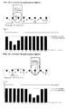
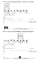
- Fig. 2 and Fig. 3 two typical signal distributions are shown in the prior art.
- the proximity of a transmitter and a receiver with the associated light reflection is referred to as sensor S (i).
- This signal distribution can be determined in time-sequential control of the transmitter 6 and respective detection of the adjacent receiver 4.
- the finger actuates the control further to the left than in Fig. 3.
- Even a small change in the position of the finger 18 leads to a noticeable change in the signal distribution of the sensors S1 to S8.
- this Effect also makes use of the present invention, as Figs. 2b and 3b show.
- FIGS. 2a and 3a how the arrangement according to the prior art reacts to a high ambient brightness (case a).
- the finger 18 happens to be located just above one of the receivers 4.
- the ambient light in this case is shaded (ie, the remaining receivers are driven to saturation by the ambient light) and the two "proximity sensors" S2 and S3 at which the shadowed receiving element 4 is involved, receive the reflected IR light in the normal working range.
- the finger 18 randomly occupies an area between two sensors, and due to the continuous saturation, there is no evaluable signal distribution.
- FIGS. 2b and 3b show the signal distribution according to the invention at normal ambient brightness (case b), FIGS. 2c and 3c at high ambient brightness (case c).
- case b the higher receiver density of the invention already provides for a better evaluable envelope with more points; in case c, an evaluation is still possible at very high ambient brightness.
- Fig. 4 shows a general formula for calculating the center of gravity of the measured light distribution.
- This center of gravity X represents the actual position of the fingertip with great accuracy.
- the result X is a value between 1 and N1 (assuming N1 receiver) and can be transformed to a different value range by suitable normalization.
- the resolution is also dependent on the quantization of the sensor signals.
- S (i) [0, 0, 2, 5, 6, 1, 0, 0].
- an extreme value can also be determined, by interpolation with a parabolic, z. B. quadratic function. This is - similar to the utility model DE 20 2004 019 489 U1 8-10, the maximum value of the parabola sought is approximated by the three most out of the frame measurements.
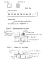
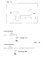
- FIG. 5b shows the structure optimized in comparison with the cited prior art according to FIG. 5a.
- the transmitter and receiver are no longer mounted alternately on the operating line 18 (FIG. 5), but the plurality N1 of IR receiving elements 4 are arranged along the operating line 16 in greater density than the number N2 of IR transmitting diodes 6.
- the IR receiving elements 4 are so dense that a finger 18 placed on the operating line 16 necessarily covers at least one of the IR receiving elements 4.
- half the number N2 of IR transmitter diodes 6 is disposed in the immediate vicinity of each second IR receiving element 4 adjacent to the operating line 16.
- the side section through the supporting circuit board 20 according to Fig. 5b shows that the optical components according to an embodiment of the invention can be arranged on the upper side of the carrier material.
- the height compared to a prior art, which is shown in Fig. 6, is substantially lower, because the previously used light guide is omitted.
- the further embodiment of the invention according to Fig. 7 shows a very low height, because the optical components (transmitter 6 and receiver 4) can even be laid on the underside of the supporting circuit board 20.
- recesses 22 are provided in the substrate 20 in this case.
- Fig. 10 shows two possibilities for such recesses 22.
- a number of optical components 4, 6 is arranged below a slot 24 which extends over the entire operating line 16.
- a smaller slot 24 is alternatively provided per optical component 4, 6. It can also satisfy a number of holes 24.
- FIGS. 8 and 9 an alternative is still shown which relates to the display elements 26.
- the display elements 26 serve to visibly display the set parameter of the hob control for the operator.
- Fig. 8 and 9 is an analog representation in the form a bargraph.
- the illustration in FIGS. 8 and 9 follows on from the embodiment according to FIG. 5a, which is readily transferable to the embodiment according to the invention according to FIG. 5b.
- the optical components 4, 6 are arranged with a small overall height on the upper side of the carrier material 20.
- the additional arrangement of the display elements 26 also applies to underlying components 4, 6, 26 as shown in Fig. 7.
- the operating line according to Fig. 5 and Fig. 5b is supplemented by the fact that display elements 26 are arranged at the intermediate positions between each two infrared sensors S1, S2, S3.
- the display elements do not interfere with the sensors 2 due to their shorter visible light wavelength, while the infrared sensors 2 do not cause a visible display due to their longer wavelength.
- Fig. 9 which in its structure with Fig. 5a bez.
- Fig. 5b instead of the infrared sensors 2 also sensors for light in the visible range are used.
- the display 26 is executed as a "bar graph" and controlled with appropriate pulse packets. At a higher density of the pulse packet, the light of the light emitting diode 6 is visible, while it remains invisible at a lower pulse packet density (controllable by pulse width modulation PWM).
- the sensor evaluation is achieved by time-division multiplexing and synchronization with the receivers 4, i. H. the light-emitting diodes 6 are activated one after the other in the direction of the operating line 16 and the receivers 4 are activated in these time windows.
- the series of light-emitting diodes 6 as a step indicator or bar graph is superimposed on the time multiplex just explained, ie a display-active light-emitting diode 6 is activated almost permanently. Since the receivers 4 are turned off at this time, the operation control operation is not affected.
- the light emitting diodes 6 which emit visible light are classified into two groups depending on the position X of the actuator or finger 18.
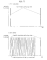
- the pulse train is used, which is shown in Fig. 11 above. These short light pulses are not visible to the human eye, but allow the receiver 4 to detect the reflected light intensity.
- This control undergoes the group of light-emitting diodes 6, which is located to the right of the finger 18 on the operating line 16.
- the other group of LEDs 6, which is located on the left of the fingertip 18 on the operating line 16 undergoes the drive shown in Fig. 11 below.
- This pulse packet makes the transmitter visible to the human eye and displays the associated heating power as a bar graph.
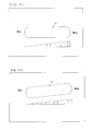
- Fig. 12a and Fig. 12b show two examples of an actuating surface 14 which is graphically displayed on the hob and below which the associated operating line 16 is located.
- the actuating surface 14 is rectilinear, i. a finger 18 may touch or linearly sweep the actuating surface 14 between the MIN and MAX values.
- On a the actuating surface 14 associated graphical symbol (wedge symbol) can be displayed in the manner of a slide control cooking level.
- the display elements can also be arranged below the actuating surface 14.
- actuating surface 14 is horizontal, obliquely aligned in Fig. 12b.
- the operating line 16 may also be curved or curved.
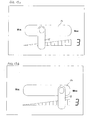
- the hob control according to the invention is operated as follows. It is possible, by touching a certain position on the actuating surface 14 directly select a cooking level, which is assigned to this position. For example, is the maximum cooking level that can be set "9" and it is the actuating surface 14 touched in the first third, so the cooking level "3" is set. This process of direct selection of the cooking level "3" is shown in Fig. 13a, wherein the cooking level 3 is displayed in this case as a digital digit for display.
- the OFF position must be precisely marked for operational safety reasons. This marking can be made in the actuating surface 14 e.g. be done by the left edge of the operation field 14 is highlighted by an OFF symbol.
- the timing of a setting operation is typically as follows: By placing the finger 18 on the operating field 14 of the cooking position sensor for a predetermined time (eg 0.5 seconds), the hotplate can be activated. If one now moves the finger 18 over the sensitive area 14, then the value X changes depending on the operation. Is now the intended X set, it must be confirmed by persisting in the appropriate position for a certain time (eg 0.3 seconds). Alternatively, of course, the value displayed after the activation of the hotplate X can be taken over by a persistence of the finger 18 (direct selection).
- a predetermined time eg 0.5 seconds
- This adjustment mode has the advantage that the complete cooking zone is seen as a sensor. For the operating line, one obtains almost the same characteristics as a single sensor, e.g. the actuation distance and the safety against an independent turning on external light concerns. In addition, by briefly holding on to the selected position (confirmation of the setting value), an oblique pulling away of the finger no longer affects the set value.
- Fig. 14 shows four straight-line embodiments of the operating line according to the invention.
- the IR transmitting diodes with the lower density are arranged in the immediate vicinity of each second IR receiving element next to the operating line. It is preferred to line up the number N2 of IR transmitting diodes only on one side of the IR receiving elements constituting the operating line 16.
- the IR-receiving elements can also form a zigzagged polygon on the overall straight line of operation.
- Each operating line can end at the edges either with a receiving element 4 and / or with a sensor pair 2 (consisting of a receiving element 4 and a transmitting diode 6).
- the operating line can be bent as shown in Fig. 15, wherein the IR-receiving elements 4 can form a zigzag-shaped polygonal line on the arcuate operating line.
- Fig. 16 shows electrical schematic diagrams of the transmitter 6 according to the invention and receiver 4.
- the transmitting diodes 6 are driven by light pulses, as shown in Fig. 11 above. These control pulses are not visible to the operator, either because the hob control has been designed as an infrared control and has been equipped with IR transmitter diodes or either because the control pulses shown in Fig. 11 above are too short to be perceptible to the human eye.
- the receivers 4 are preferably designed as IR phototransistors. According to the wiring in Fig. 16, an increased light intensity leads to a voltage drop of the emitter signal to saturation. Subsequently, the measurement signal can be normalized to be proportional to the intensity of the light signal to which the photoreceiver (including daylight filter) is sensitive. Such normalized light measuring signals are shown by way of example in the distributions according to FIGS. 2 and 3.
Landscapes
- Engineering & Computer Science (AREA)
- Chemical & Material Sciences (AREA)
- Combustion & Propulsion (AREA)
- Mechanical Engineering (AREA)
- General Engineering & Computer Science (AREA)
- Electronic Switches (AREA)
Applications Claiming Priority (1)
| Application Number | Priority Date | Filing Date | Title |
|---|---|---|---|
| DE102006052875A DE102006052875B4 (de) | 2006-11-09 | 2006-11-09 | Anordnung zum Einstellen eines Haushaltsgeräts |
Publications (1)
| Publication Number | Publication Date |
|---|---|
| EP1921386A2 true EP1921386A2 (fr) | 2008-05-14 |
Family
ID=38983513
Family Applications (1)
| Application Number | Title | Priority Date | Filing Date |
|---|---|---|---|
| EP07119886A Withdrawn EP1921386A2 (fr) | 2006-11-09 | 2007-11-02 | Commande de champ de cuisson et procédé de réglage manuel sur une ligne de commande |
Country Status (3)
| Country | Link |
|---|---|
| US (1) | US8164032B2 (fr) |
| EP (1) | EP1921386A2 (fr) |
| DE (1) | DE102006052875B4 (fr) |
Cited By (1)
| Publication number | Priority date | Publication date | Assignee | Title |
|---|---|---|---|---|
| EP2224174A3 (fr) * | 2009-02-26 | 2010-09-15 | E.G.O. ELEKTRO-GERÄTEBAU GmbH | Hotte aspirante et procédé de commande correspondant |
Families Citing this family (6)
| Publication number | Priority date | Publication date | Assignee | Title |
|---|---|---|---|---|
| US8479720B1 (en) | 2008-10-16 | 2013-07-09 | Oscar Enrique Figueroa | Heating device and method |
| DE102009011678A1 (de) * | 2009-02-23 | 2010-08-26 | E.G.O. Elektro-Gerätebau GmbH | Bedieneinrichtung für ein Elektro-Hausgerät und Bedienverfahren |
| US8041956B1 (en) * | 2010-08-16 | 2011-10-18 | Daon Holdings Limited | Method and system for biometric authentication |
| CN101853110B (zh) * | 2010-06-02 | 2012-08-29 | 鸿富锦精密工业(深圳)有限公司 | 具有红外触摸功能的电子装置 |
| DE102012203954A1 (de) | 2012-03-14 | 2013-09-19 | Zf Friedrichshafen Ag | Näherungssensor und damit gebildetes Bedienfeld |
| DE102015210903A1 (de) * | 2015-06-15 | 2016-12-15 | Ifm Electronic Gmbh | Messgerät der Automatisierungstechnik |
Family Cites Families (6)
| Publication number | Priority date | Publication date | Assignee | Title |
|---|---|---|---|---|
| US3621268A (en) * | 1967-12-19 | 1971-11-16 | Int Standard Electric Corp | Reflection type contactless touch switch having housing with light entrance and exit apertures opposite and facing |
| GB2173931B (en) * | 1985-04-16 | 1988-05-11 | Ncr Co | Data input system including a keyboard having no moving parts |
| DE10337743A1 (de) * | 2003-08-13 | 2005-03-10 | Ego Elektro Geraetebau Gmbh | Verfahren sowie Schaltungsanordnung zur Ermittlung des Betätigungszustandes mindestens eines optischen Sensorelements |
| DE10359561B4 (de) * | 2003-12-18 | 2006-05-04 | Diehl Ako Stiftung & Co. Kg | Bedienelement für ein Haushaltsgerät |
| DE102004024835B3 (de) * | 2004-05-19 | 2005-10-13 | Cherry Gmbh | Sensoranordnung für eine Pseudokontinuierliche Betätigung |
| DE102004054322B3 (de) * | 2004-11-10 | 2006-06-29 | Cherry Gmbh | Verfahren und Anordnung zum Einstellen an einer Bedienlinie |
-
2006
- 2006-11-09 DE DE102006052875A patent/DE102006052875B4/de not_active Expired - Fee Related
-
2007
- 2007-10-17 US US11/975,116 patent/US8164032B2/en not_active Expired - Fee Related
- 2007-11-02 EP EP07119886A patent/EP1921386A2/fr not_active Withdrawn
Cited By (1)
| Publication number | Priority date | Publication date | Assignee | Title |
|---|---|---|---|---|
| EP2224174A3 (fr) * | 2009-02-26 | 2010-09-15 | E.G.O. ELEKTRO-GERÄTEBAU GmbH | Hotte aspirante et procédé de commande correspondant |
Also Published As
| Publication number | Publication date |
|---|---|
| US20080221735A1 (en) | 2008-09-11 |
| DE102006052875A1 (de) | 2008-05-15 |
| US8164032B2 (en) | 2012-04-24 |
| DE102006052875B4 (de) | 2013-07-25 |
Similar Documents
| Publication | Publication Date | Title |
|---|---|---|
| DE102004054322B3 (de) | Verfahren und Anordnung zum Einstellen an einer Bedienlinie | |
| EP1921386A2 (fr) | Commande de champ de cuisson et procédé de réglage manuel sur une ligne de commande | |
| EP2290820B1 (fr) | Procédé de saisie d'une valeur à deux chiffres dans un dispositif de commande | |
| DE102007057076A1 (de) | Kochfeld und Verfahren zum Betrieb eines Kochfeldes | |
| EP2282126B1 (fr) | Hotte aspirante dotée d'une unité de commande | |
| WO2003009476A1 (fr) | Dispositif optoelectronique de detection de position et de mouvement et procede correspondant | |
| DE102005018298A1 (de) | Verfahren zur Ansteuerung und/oder Auswertung eines länglichen Sensorelements einer Bedieneinrichtung und eine solche Bedieneinrichtung | |
| DE4010998C2 (fr) | ||
| DE102013203930A1 (de) | Verfahren und Vorrichtung zur Steuerung eines Elektrogeräts | |
| DE102005025782B4 (de) | Berührungsempfindlicher Tastschalter | |
| EP2837891B1 (fr) | Plaque de cuisson | |
| DE102009012004A1 (de) | Dunstabzugshaube und Bedienverfahren dafür | |
| EP1533630B1 (fr) | Barrière lumineuse de sécurité | |
| EP2767761B1 (fr) | Gamme d'appareils ménagers et procédé de fabrication d'appareils ménagers à commandes différentes | |
| EP3330617B1 (fr) | Plaque de cuisson et procédé de fonctionnement d'une telle plaque de cuisson | |
| EP1810405B1 (fr) | Arrangement comprenant un plan de travail et une plaque en vitrocéramique arrangée dedans | |
| EP3537049A1 (fr) | Procédé de représentation d'un affichage sur un champ de cuisson et champ de cuisson | |
| DE10359561B4 (de) | Bedienelement für ein Haushaltsgerät | |
| WO2006050818A1 (fr) | Curseur optique | |
| DE102009022898A1 (de) | Kochfeld | |
| DE19851505C2 (de) | Schaltelement | |
| DE202010007687U1 (de) | Bedienungsvorrichtung, insbesondere für einen motorisch angetriebenen Rollladen | |
| DE102010039070A1 (de) | Haushaltsgerät mit einem Kochfeld und Verfahren zum Anzeigen eines Energieverbrauchs | |
| EP3579415A1 (fr) | Procédé de commande d'un appareil de cuisson électrique et appareil de cuisson électrique | |
| EP1662354B1 (fr) | Dispositif d'actionnement destiné à une robinetterie sanitaire, en particulier électronique, et procédé destiné au fonctionnement d'un tel dispositif |
Legal Events
| Date | Code | Title | Description |
|---|---|---|---|
| PUAI | Public reference made under article 153(3) epc to a published international application that has entered the european phase |
Free format text: ORIGINAL CODE: 0009012 |
|
| 17P | Request for examination filed |
Effective date: 20071102 |
|
| AK | Designated contracting states |
Kind code of ref document: A2 Designated state(s): AT BE BG CH CY CZ DE DK EE ES FI FR GB GR HU IE IS IT LI LT LU LV MC MT NL PL PT RO SE SI SK TR |
|
| AX | Request for extension of the european patent |
Extension state: AL BA HR MK RS |
|
| RAP1 | Party data changed (applicant data changed or rights of an application transferred) |
Owner name: ZF ELECTRONICS GMBH |
|
| RAP1 | Party data changed (applicant data changed or rights of an application transferred) |
Owner name: ZF FRIEDRICHSHAFEN AG |
|
| STAA | Information on the status of an ep patent application or granted ep patent |
Free format text: STATUS: THE APPLICATION IS DEEMED TO BE WITHDRAWN |
|
| 18D | Application deemed to be withdrawn |
Effective date: 20160601 |