EP1921417A1 - Appareil d'évaluation de distorsion et procédé d'évaluation de distorsion - Google Patents
Appareil d'évaluation de distorsion et procédé d'évaluation de distorsion Download PDFInfo
- Publication number
- EP1921417A1 EP1921417A1 EP06768084A EP06768084A EP1921417A1 EP 1921417 A1 EP1921417 A1 EP 1921417A1 EP 06768084 A EP06768084 A EP 06768084A EP 06768084 A EP06768084 A EP 06768084A EP 1921417 A1 EP1921417 A1 EP 1921417A1
- Authority
- EP
- European Patent Office
- Prior art keywords
- distortion
- data
- cross
- evaluating
- section
- Prior art date
- Legal status (The legal status is an assumption and is not a legal conclusion. Google has not performed a legal analysis and makes no representation as to the accuracy of the status listed.)
- Withdrawn
Links
Images


Classifications
-
- G—PHYSICS
- G01—MEASURING; TESTING
- G01B—MEASURING LENGTH, THICKNESS OR SIMILAR LINEAR DIMENSIONS; MEASURING ANGLES; MEASURING AREAS; MEASURING IRREGULARITIES OF SURFACES OR CONTOURS
- G01B11/00—Measuring arrangements characterised by the use of optical techniques
- G01B11/30—Measuring arrangements characterised by the use of optical techniques for measuring roughness or irregularity of surfaces
- G01B11/306—Measuring arrangements characterised by the use of optical techniques for measuring roughness or irregularity of surfaces for measuring evenness
-
- B—PERFORMING OPERATIONS; TRANSPORTING
- B62—LAND VEHICLES FOR TRAVELLING OTHERWISE THAN ON RAILS
- B62D—MOTOR VEHICLES; TRAILERS
- B62D65/00—Designing, manufacturing, e.g. assembling, facilitating disassembly, or structurally modifying motor vehicles or trailers, not otherwise provided for
- B62D65/005—Inspection and final control devices
-
- G—PHYSICS
- G01—MEASURING; TESTING
- G01B—MEASURING LENGTH, THICKNESS OR SIMILAR LINEAR DIMENSIONS; MEASURING ANGLES; MEASURING AREAS; MEASURING IRREGULARITIES OF SURFACES OR CONTOURS
- G01B11/00—Measuring arrangements characterised by the use of optical techniques
- G01B11/24—Measuring arrangements characterised by the use of optical techniques for measuring contours or curvatures
-
- G—PHYSICS
- G01—MEASURING; TESTING
- G01N—INVESTIGATING OR ANALYSING MATERIALS BY DETERMINING THEIR CHEMICAL OR PHYSICAL PROPERTIES
- G01N21/00—Investigating or analysing materials by the use of optical means, i.e. using sub-millimetre waves, infrared, visible or ultraviolet light
- G01N21/84—Systems specially adapted for particular applications
- G01N21/88—Investigating the presence of flaws or contamination
- G01N21/95—Investigating the presence of flaws or contamination characterised by the material or shape of the object to be examined
- G01N21/9515—Objects of complex shape, e.g. examined with use of a surface follower device
-
- G—PHYSICS
- G06—COMPUTING OR CALCULATING; COUNTING
- G06T—IMAGE DATA PROCESSING OR GENERATION, IN GENERAL
- G06T7/00—Image analysis
- G06T7/0002—Inspection of images, e.g. flaw detection
- G06T7/0004—Industrial image inspection
- G06T7/0006—Industrial image inspection using a design-rule based approach
-
- G—PHYSICS
- G06—COMPUTING OR CALCULATING; COUNTING
- G06T—IMAGE DATA PROCESSING OR GENERATION, IN GENERAL
- G06T2200/00—Indexing scheme for image data processing or generation, in general
- G06T2200/04—Indexing scheme for image data processing or generation, in general involving 3D image data
Definitions
- the present invention relates to an apparatus and a method for evaluating distortion based on three-dimensional measurement data obtained from a measurement object surface.
- a distortion evaluating apparatus designed to extract mechanically a certain characteristics from the distortion in the measurement object surface such as a body surface, thereby effecting the sensory evaluation of distortion degree in a quantitative manner.
- a secondary differential operation is carried out on two-dimensional measurement data of a cross section of the measurement object surface, indicative of unevenness of the surface and then e.g. a difference value between the maximum value and the minimum value of the secondary differential values, as the characteristics indicative of the distortion. Thereafter, this difference value is assigned into a prediction formula, by which a distortion evaluation value is predicted. More particularly, a difference between a cross section shape line of the measurement object surface actually determined and an ideal curve of values which comprise e.g. design data per se is calculated, thus obtaining a surface distortion line including all large and small distortions which have developed in the measurement object surface.
- this secondary differential operation is effected on this surface distortion line obtained with including all large and small distortions, and a difference value between the maximum value and the minimum value of the resultant secondary differential values is utilized for the distortion evaluation.
- the secondary differential values of this two-dimensional measurement data correspond to curvature data of the cross section of the measurement object surface. And, it may be determined that the greater the absolute value of the secondary differential value, the greater the distortion.
- Patent Document 1 Japanese Patent No. 3015615
- the apparatus employs a difference value between the maximum value and the minimum value of two-dimensional measurement data, as a characteristics used for distortion degree evaluation.
- the apparatus employs data including all, i.e. large and small distortions present in the measurement object surface, for the purpose of distortion evaluation of the measurement object surface.
- a sensory evaluation by a human on the other hand, even when a distortion exists, this may sometimes be determined as permissible if it is not conspicuous.
- the method is configured to take note of and find problematic even such small distortion also which would be found permissible by a sensory evaluation by a human.
- a certain waveform can have a large peak (maximum value) of absolute value in the positive direction and has a small peak (minimum value) of absolute value in the negative direction.
- Another waveform can have equal peaks (maximum value and minimum value) of absolute value in the positive direction and negative direction.
- Still another waveform can have a small peak (minimum value) of absolute value in the positive direction and has a large peak (maximum value) of absolute value in the negative direction.
- the distortion evaluating apparatus described in Patent Document 1 would provide a same distortion evaluation result for all of these three kinds of waveforms as long as the difference value between the maximum value and the minimum value of the secondary differential values is the same.
- the original shape of the measurement object surface to be used as the baseline can sometimes be deformed by the spring-back phenomenon of the steel plate, so that the cross section line obtained therefrom may deviate from the design data.
- the conventional method would determine such original shape of the measurement object surface too as "distortion", which actually is not.
- the distortion evaluating apparatus disclosed in Patent Document 1 is configured to attempt to calculate difference values between a cross section shape line and an ideal curve so as to obtain a surface distortion line which includes only the distortions which have developed in the measurement object surface.
- the above difference values include not only the distortions, but also the original shape of the measurement object surface.
- even if no distortion has actually developed there is the possibility of the original shape of the measurement object surface formed by the spring back being determined as a distortion erroneously.
- the apparatus monitors the secondary differential values and calculates a difference value between the maximum and minimum values thereof.
- the apparatus monitors the secondary differential values and calculates a difference value between the maximum and minimum values thereof.
- the present invention has been made in view of the above-described problem. And, its object is to provide an apparatus and a method for evaluating distortion which can quantitatively evaluate distortion in a measurement object surface.
- a distortion evaluating apparatus for evaluating distortion based on three-dimensional measurement data obtained from a measurement object surface, the apparatus comprises:
- the curvature data of the cross section refer to data obtained by first effecting a differential operation on the two-dimension measurement data of the cross section thus obtaining slope data for each point of the cross section and then effecting a secondary differential operation on the slope data for each point of the cross section, so that the resultant data may indicate a change in the slopes of the cross section.
- the slope of the cross section changes by a fixed amount, so that the slope change amount of each point of the cross section will be constant.
- the secondary differential means extracts the curvature data of the cross section by effecting a secondary differential operation on the two dimension measurement data of a predetermined cross section indicative of unevenness therein.
- the secondary differential means effects a secondary differential operation on two-dimensional measurement data of a cross section of the measurement object surface indicative of unevenness therein, thus obtaining curvature data of the cross section.
- the permissible range setting means sets a permissible range for said curvature data, based on range of an upper limit value and a lower limit value from a reference value.
- the distortion data extracting means extracts a portion of said curvature data exceeding said set permissible range as distortion data indicative of the distortion in the cross section. That is to say, the distortion evaluating apparatus having the above-described characterizing feature effects a data processing operation which does not determine curvature data with small absolute values within the set permissible range as any distortion. This data processing operation is identical to the above-described human sensory evaluation which disregards small distortions.
- the permissible range setting means sets the permissible range for the curvature data, based on a range of an upper limit value and a lower limit value from a reference value, it is possible to set desirably which portion of the curvature data to be extracted as the distortion data. That is to say, even when the original shape of the measurement object surface has been deformed due to a spring back of the steel plate, by appropriately increasing/decreasing the reference value corresponding to the original shape in accordance with the deformed shape so that the increased/decreased reference value may be substantially equal to the secondary differential value of the cross section indicative of the original shape, it is possible not to erroneously determine the originally deformed shape due to the spring back as distortion.
- the distortion data extracting means is to effect only the comparison between the set permissible range with the curvature data in order to extract the distortion data, no significant computational load will be applied to the distortion evaluating apparatus.
- the distortion data on which the inventive distortion evaluating apparatus effects the distortion evaluation is analogous to information on which a human worker effects his/her sensory evaluation. Hence, distortion in a measurement object surface can be evaluated quantitatively.
- said permissible range setting means changes at least one of said reference value, said upper limit value and said lower limit value, in accordance with a characteristics of said measurement object surface.
- the secondary differential value of its cross section will be zero (the curvature data of the cross section will be zero).
- the curvature data of the cross section indicative of this cross section shape may exceed the set permissible range. In such case, even in the absence of any distortion, the curvature data of the cross section indicative of the original shape of the measurement object surface may be determined as distortion data erroneously.
- the permissible range setting means changes at least one of said reference value, said upper limit value and said lower limit value, in accordance with a characteristics of said measurement object surface, distortion which has actually developed in the measurement object surface can be extracted as distortion data selectively. As a result, distortion in a measurement object surface can be evaluated quantitatively.
- said secondary differential means extracts said curvature data for each one of a plurality of cross sections over said measurement object surface three-dimensionally;
- said distortion data extracting means includes distortion degree evaluating means for extracting said distortion data for each one of said cross sections three dimensionally;
- said distortion evaluating apparatus further comprises a distortion degree evaluating means for evaluating a degree of distortion in a specific distorted region present in said measurement object surface, based on said three dimensional distortion data.
- the distortion degree evaluating means evaluates a degree of distortion in a specific distorted region present in said measurement object surface, based on said three dimensional distortion data, it is possible to determine quantitatively a degree of distortion included in the three dimensional shape of the measurement object surface.
- the apparatus further comprises a distortion length extracting means for extracting the length of said specific distorted region based on three dimensional distortion data and a distortion volume extracting means for extracting the volume of said specific distorted region based on the three dimensional distortion data; and said distortion degree evaluating means evaluates the degree of distortion in the specific distorted region by using the combination of the length and the volume of the specific distorted region as distortion evaluation data and comparing evaluation reference data and the distortion evaluation data with each other.
- the distortion length extracting means extracts the length of said specific distorted region based on the three dimensional distortion data and the distortion volume extracting means extracts the volume of said specific distorted region based on the three dimensional distortion data.
- the distortion degree evaluating means evaluates the degree of distortion in the specific distorted region by using the combination of the length and the volume of the specific distorted region as distortion evaluation data and comparing evaluation reference data and the distortion evaluation data with each other. Therefore, it is possible to determine quantitatively a degree of distortion included in the three dimensional shape of the measurement object surface, with using the characteristics (length and volume of the distorted region) included in the three dimensional distortion data of the measurement object surface.
- the apparatus further comprises a distortion length extracting means for extracting the length of said specific distorted region based on three dimensional distortion data and a distortion area extracting means for extracting the area of said specific distorted region based on the three dimensional distortion data by integrating widths of the specific distorted region perpendicular to the length along the direction of this length; and said distortion degree evaluating means evaluates the degree of distortion in the specific distorted region by using the combination of said length and said area of the specific distorted region as distortion evaluation data and comparing evaluation reference data and said distortion evaluation data with each other.
- the distortion length extracting means extracts the length of said specific distorted region based on three dimensional distortion data and the distortion area extracting means extracts the area of said specific distorted region based on the three dimensional distortion data by integrating widths of the specific distorted region perpendicular to the length along the direction of this length.
- the distortion degree evaluating means evaluates the degree of distortion in the specific distorted region by using the combination of said length and said area of the specific distorted region as distortion evaluation data and comparing evaluation reference data and the distortion evaluation data with each other. Therefore, it is possible to determine quantitatively a degree of distortion included in the three dimensional shape of the measurement object surface, with using the characteristics (length and area of the distorted region) included in the three dimensional distortion data of the measurement object surface.
- a distortion evaluating method for evaluating distortion based on three-dimensional measurement data obtained from a measurement object surface comprises the steps of:
- a secondary differential operation is effected on two-dimensional measurement data of a cross section of the measurement object surface indicative of unevenness therein, thus obtaining curvature data of the cross section.
- the method sets a permissible range for said curvature data, based on a range of an upper limit value and a lower limit value from a reference value.
- a portion of said curvature data exceeding said set permissible range is extracted as distortion data indicative of the distortion in the cross section. That is to say, the distortion evaluating method having the above-described characterizing feature effects a data processing operation which does not determine curvature data with small absolute values within the set permissible range as any distortion. This data processing operation is identical to the human sensory evaluation which disregards small distortions.
- the method sets the permissible range for the curvature data, based on a range of an upper limit value and a lower limit value from a reference value, it is possible to set desirably which portion of the curvature data is to be extracted as the distortion data. That is to say, even when the original shape of the measurement object surface has been deformed due to a spring back of the steel plate, by appropriately increasing/decreasing the reference value corresponding to the original shape in accordance with the deformed shape so that the increased/decreased reference value may be substantially equal to the secondary differential value of the cross section indicative of the original shape, it is possible not to erroneously determine the originally deformed shape due to the spring back as distortion.
- the distortion data on which the inventive distortion evaluating method effects the distortion evaluation is analogous to information on which a human effects his/her sensory evaluation. Hence, distortion in a measurement object surface can be evaluated quantitatively.
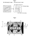
- Fig. 1 shows a functional block diagram of a non-contact, three dimensional measurement system and a distortion evaluating apparatus 40 relating to a first embodiment of the present invention.
- This non-contact three dimensional measurement system is used for effecting non-contact, three-dimensional measurement of a shape of a door panel manufactured by press-working a steel plate in a mold.
- this three-dimensional measurement system includes a robot hand 10 as a measuring head moving means, a non-contact three-dimensional measuring means 20 for effecting checkered pattern analysis of a grating pattern photographic image projected on a measurement object surface while being shifted in phase under a tracking scanning of the door panel by the robot hand 10, thus obtaining three dimensional coordinate values for each pixel of the imaging image and outputting a measurement image with three dimensional distance data assigned to respective pixels thereof (More precisely, values of pixels constituting the image comprise the three dimensional distance data.
- this image is different from an ordinary image, but will be referred to herein as "measurement image” for facilitating understanding), and a three dimensional measurement control unit 30 for processing measurement images of respective portions of the door panel transferred one after another from the non-contact three dimensional measuring means 20 and then generating three dimensional measurement data of the entire door panel.
- the distortion evaluating apparatus 40 can be realized by combination of an arithmetic processing unit such as a computer and a predetermined program.
- the robot hand 10 per se is a known device consisting essentially of an arm mechanism 11 having, at a leading end thereof, a tool attaching portion 11a which is movable three-dimensionally and a robot hand controller 12 for controlling the movements of this arm mechanism 11.
- the non-contact three dimensional measuring means 20 includes a measuring head 21 having a checkered pattern projecting portion 21a acting as a projector for projecting a grating pattern onto a measurement object surface and a camera portion 21b for imaging a grating image which is deformed as being projected on the measurement object surface, a control portion 22 for controlling the checkered pattern projecting portion 21a, the camera portion 21b, etc. and a three dimensional distance data measuring portion 23 for analyzing the image transmitted from the camera portion 21b and then generating and outputting the above-described measurement image.
- a measuring head 21 having a checkered pattern projecting portion 21a acting as a projector for projecting a grating pattern onto a measurement object surface and a camera portion 21b for imaging a grating image which is deformed as being projected on the measurement object surface, a control portion 22 for controlling the checkered pattern projecting portion 21a, the camera portion 21b, etc. and a three dimensional distance data measuring portion 23 for analyzing the image transmitted from the camera portion 21b
- Japanese Patent Application "Kokai” No. 2004-317495 and Japanese Patent Application “Kokai” No. 2002-257528 As the measuring head 21 is attached to the tool attaching portion 11a of the robot hand 10, the measuring head 21 can be moved to a desired position for effecting the three dimensional measurement.
- the photographic image shows a deformed grating pattern formed as the grating pattern projected onto the measurement object surface by the checkered pattern projecting portion 21a is deformed due to shape change or curvature of the measurement object surface, the deformed grating pattern being shown as density variations which are pixel values of respective pixels constituting this photographic image.
- the three dimensional coordinate values of the respective pixel (this need not necessarily have one-to-one relationship with the pixel of the photographic image), that is, the three dimensional distance data.
- the data comprising the three dimensional distance data assigned instead of the density as the pixel value of each pixel is referred to as "measurement image" herein.
- a certain pixel Pn of the measurement image is to have three dimensional coordinate values (three dimensional distance data) as (Xn, Yn, Zn).
- the three dimensional measurement data generated as above is then transferred from the three dimensional measurement control unit 30 to the distortion evaluating apparatus 40.
- the construction of this distortion evaluating apparatus 40 and the distortion evaluating method effected with using the distortion evaluating apparatus 40 will be described.
- the distortion evaluating apparatus 40 includes a secondary differential means 41 for effecting a secondary differential operation on two-dimensional measurement data of a predetermined cross section of the measurement object surface indicative of unevenness therein, thus obtaining curvature data of the cross section, a permissible range setting means 43 for setting a permissible range for the curvature data, based on a range of an upper limit value and a lower limit value from a reference value, and a distortion data extracting means 42 for extracting a portion of the curvature data exceeding said set permissible range as distortion data indicative of the distortion in the cross section.
- the secondary differential means 41 obtains the curvature data of a plurality of respective cross sections over the measurement object surface three dimensionally.
- the secondary differential means 41 is used for obtaining curvature data of cross sections. More particularly, when a differential operation is effected on two dimensional measurement data of a cross section, there is obtained slope data for each point in the cross section. Further, when a further differential operation is effected on this slope data for each point of the cross section, there is obtained slope change data. For example, in the case of a cross section with a fixed curvature, such as a circle, the slope of the cross section changes by a fixed amount, so that the slope change amount of each point of the cross section will be constant. Whereas, in the case of a cross section with a plurality of curvatures, such as a sine waveform, the slope change amount for each point in the cross section is not constant. As described above, it may be said that the secondary differential means 41 extracts the curvature data of the cross section by effecting a secondary differential operation on the two dimension measurement data of a predetermined cross section indicative of unevenness therein.
- Fig. 3 shows distortion data to be described later in a grey scale corresponding to the magnitudes of values thereof. More particularly, the cross section curvature data obtained by the secondary differential means 41 are drawn three dimensionally for a plurality of mutually parallel cross sections of the measurement object surface.
- a door handle attaching portion 2 is used as an example of the measurement object surface. As shown in Fig. 3 , the door handle attaching portion 2 is laid laterally and there are developed distorted regions G1 through G4 at total four positions, i.e. at right and left ends and upper and lower positions of the attaching portion 2.
- Fig. 3 shows distortion data to be described later in a grey scale corresponding to the magnitudes of values thereof. More particularly, the cross section curvature data obtained by the secondary differential means 41 are drawn three dimensionally for a plurality of mutually parallel cross sections of the measurement object surface.
- a door handle attaching portion 2 is used as an example of the measurement object surface. As shown in Fig. 3 , the door handle attaching portion 2 is laid laterally
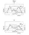
- FIG. 4 (a) shows a graph including a shape line (shown by a dot line) of a cross section A-A' at a position distant by a distance (a) in an upper direction (positive direction along the L-axis) from the door handle attaching portion 2 and curvature data (shown by a solid line) obtained as the result of the secondary differential operation on the two dimensional measurement data thereof.
- FIG. 4 (b) shows a graph including a shape line (shown by a dot line) of a cross section B-B' at a position distant by a distance (b) in the upper direction (positive direction along the L-axis) from the door handle attaching portion 2 and curvature data (shown by a solid line) obtained as the result of the secondary differential operation on the two dimensional measurement data thereof.
- the respective curvature data comprises data (1/p) obtained by multiplying the data obtained by the secondary differential of the two dimensional measurement data of the cross section, with a value of "-1".
- "p" is the radius of the circumference forming the cross section.
- Fig. 4 shows also the set permissible range for the curvature data.
- This set permissible range is set by the permissible range setting means 43 as a range between an upper limit value and a lower limit value relative to a predetermined reference value.
- This set permissible range is used for extracting, from the above-described curvature data, distortion data indicative of distortion in the cross section.
- the reference value is set, based on the original cross section shape of the measurement object surface. That is, the reference value can be a secondary differential value obtained by effecting a secondary differential operation on a cross section of the measurement object surface which is still free from any distortion.
- a distortion develops in the measurement object surface, this causes deviation of the curvature data of the cross section from the reference value. More particularly, if a distortion with a small curvature occurs in the measurement object surface (i.e. a distortion with a gently varying slope at each point of the cross section), this will appear as a small amount of deviation of the curvature data of the cross section from the reference value. On the other hand, if a distortion with a large curvature occurs in the measurement object surface (i.e. a distortion with a sharply varying slope at each point of the cross section), this will appear as a large amount of deviation of the curvature data of the cross section from the reference value. Therefore, a portion with curvature data thereof being within the set permissible range can be determined not to be a distortion, whereas a portion with curvature data thereof exceeding the set permissible range can be determined to be a distortion.
- the distortion data extracting means 42 extracts, from among the curvature data, data over the upper limit value and data below the lower limit value as distortion data indicative of the distortion in that cross section.
- a distortion degree evaluating means 46 evaluates a degree of distortion in a specific distorted region present in the measurement object surface, based on the three dimensional distortion data obtained over the measurement object surface.
- Fig. 3 shows distortion data extracted by the distortion data extracting means 42 being shown in grey scale distribution according to magnitudes of values thereof. This can be displayed by a display device (not shown) connected to the distortion evaluating apparatus 40. That is, this Fig. 3 shows values exceeding the set permissible range and values below the set permissible range, from among the cross section curvature data. And, in the instant embodiment, as shown, there are developed the total of four distorted regions G1-G4 in the periphery of the attaching portion 2. And, in this embodiment, the width extension of the distorted region along the direction normal to each cross section (L-axis direction) is defined as a distortion length: L ( Fig. 3 shows the distortion length L1 of the distorted region G1). A distortion length extracting means 44 is provided for automatically extracting the respective length of the specific distorted region such as the regions G1 through G4 described above, based on the three dimensional distortion data extracted by the distortion data extracting means 42.
- Fig. 5 is a graph schematically showing curvature data for a plurality of respective cross sections and the upper limit values of the above-described set permissible range.
- the data exceeding the upper limit values are the distortion data.
- the region exceeding the upper limit value for each cross section will be referred to as a cross sectional area: S1. Therefore, a region where a plurality of such cross sectional areas: S1 are present will be determined as a distorted region: Ga, Gb.
- a distortion volume extracting means 45 extracts the volume of each distorted region: Ga, Gb by multiplying the cross sectional areas: S1 for the respective cross sections over the distortion length L.
- the distortion degree evaluating means 46 employs the combination of the length and the volume of the specific distorted region as distortion evaluation data and compares this distortion evaluation data with a predetermined evaluation reference data, thus evaluating the degree of the specific distortion.
- This evaluation reference data can be obtained empirically by comparing result of a human sensory evaluation on a specific distorted region and the distortion evaluation data comprising the length and the volume of the distorted region obtained according to the present embodiment as above.
- Fig. 6 is a graph showing such result of comparison between the distortion evaluation data and evaluation reference data, plotting altogether distortion evaluation data extracted for 10 (ten) distorted regions by the distortion evaluating apparatus 40 of the invention.
- This graph showing comparison result can be displayed on a display device (not shown) to be connected to the distortion evaluating apparatus 40.
- the horizontal axis represents the distortion length whereas the vertical axis represents the distortion volume.
- human sensory evaluations were carried out respectively therefor.
- the results of the sensory evaluations (from five points (good) to one point (poor)) are indicated with using different markers for the plottings thereof.
- the evaluation reference data are set such that the longer the distortion length and the greater the distortion volume, the lower (poorer) the evaluation of the degree of distortion in the distorted region.
- the inventive distortion evaluating apparatus 40 for the three distorted regions for which the human sensory evaluations provided poor results (from one to two points), similarly poor evaluation results were provided by the inventive distortion evaluating apparatus 40 also.
- similarly poor evaluation results were provided by the inventive distortion evaluating apparatus 40 also.
- similarly good evaluation results were provided by the inventive distortion evaluating apparatus 40 also.
- the distortion degree evaluation effected by the distortion degree evaluating means 46 by using the combination of the length (i.e. the width extension of the distorted region) and the volume (i.e. the strength of the distorted region) as the distortion evaluation data and making comparison between this distortion evaluation data with the predetermined evaluation reference data is found to be consistent with the human sensory evaluation result.
- the distortion evaluating apparatus 40 effects a data processing operation which does not interpret curvature data with a small absolute value within a set permissible range as a distortion. And, this data processing is substantially equivalent to a sensory evaluation made by a human who finds a small distortion as permissible. That is to say, the above-described distortion data on which the result of distortion evaluation by the distortion evaluating apparatus 40 of this embodiment is based is analogous to the information on which the result of the human sensory evaluation is based.
- a result of evaluation of distortion degree conventionally relied on a human sensor evaluation by a skilled artisan can now be quantitatively obtained by the distortion evaluating apparatus 40 of the present embodiment.
- a distortion which requires correction can be easily determined under a certain constant standard, whereby unnecessary distortion correction or unnecessary repetition of distortion correction can be avoided advantageously.
- a distortion which has developed on a body surface (e.g. a door panel surface of a motorcar) manufactured by press working can be discovered properly under the predetermined standard. Therefore, it is possible to make an appropriate correction on the mold used for this press working operation so as not to develop any distortion thereafter. That is, the distortion evaluating apparatus 40 of the invention can be utilized also for inspection of a mold to be used in press working.
- a distortion evaluating apparatus 50 relating to the second embodiment differs from that the first embodiment in that the distortion degree evaluating means 46 employs the combination of the length and the area of a specific distorted region as the distortion evaluation data.
- the distortion evaluating apparatus 50 according to the second embodiment will be described. The following discussion, however, will omit discussion of same or substantially same constructions as those of the first embodiment.
- Fig. 7 shows a functional block diagram of the non-contact, three dimensional measurement system and distortion evaluating apparatus 50 relating to the second embodiment.
- the distortion evaluating apparatus 50 includes a distortion area extracting means 47 for extracting the area of a specific distorted region, and the distortion degree evaluating means 46 employs the combination of the length and the area of the specific distorted region as the distortion evaluation data and effects comparison between this distortion evaluation data and the evaluation reference data for evaluating the degree of distortion in the specific distorted region.
- Fig.8 is a graph schematically showing curvature data for a plurality of respective cross sections and the upper limit value of the above-described set permissible range.
- a length of the portions intersecting with the upper limit value i.e. a width: W of the distorted region.
- the distortion area extracting means 47 obtains the area S2 of this specific distorted region by integrating the widths: W of the specific distorted region perpendicular to the length along the length direction (L-axis direction), based on the three dimensional distortion data extracted by the distortion data extracting means 42.
- the distortion degree evaluating means 46 employs the combination of the length and the area of the specific distorted region as distortion evaluation data and compares this distortion evaluation data with a predetermined evaluation reference data, thus evaluating the degree of the specific distortion.
- Fig. 9 is a graph showing such result of comparison between the distortion evaluation data and evaluation reference data, plotting altogether distortion evaluation data extracted for 10 (ten) distorted regions by the distortion evaluating apparatus 50 of the invention.
- the horizontal axis represents the distortion length whereas the vertical axis represents the distortion area.
- human sensory evaluations were carried out respectively therefor.
- the results of the sensory evaluations (from five points (good) to one point (poor)) are indicated with using different markers for the plottings thereof.
- the evaluation reference data are set such that the longer the distortion length and the greater the distortion area, the lower (poorer) the evaluation of the degree of distortion in the distorted region.
- the evaluation reference data can be obtained empirically by comparing the result of a human sensory evaluation on a specific distorted region and the distortion evaluation data comprising the length and the area of the distorted region obtained according to the present embodiment as above.
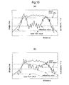
- the permissible range setting means 43 can variably set the reference value, the upper limit value and the lower limit value as desired.
- Fig. 10 (a) shows an example setting in which of the set permissible range shown in Fig. 4 (a) , the upper limit value is changed.
- the upper limit value and the lower limit value can be set smaller so as to allow even small curvature data to be extracted as distortion data.
- Fig. 10 (b) shows another example setting in which of the set permissible range shown in Fig. 4 (b) , the reference value of a specific portion of the measurement object surface is changed. More particularly, the reference value is partially reduced. In this way, not only the upper limit value and the lower limit value, the reference value too can be changed. For instance, in case the curvature data is not zero as the original cross section shape of the measurement object surface is not flat, but curved, the secondary differential data (curvature data) of the original cross section shape of the measurement object surface can be set as the reference value.
- the reference value, the upper limit value and the lower limit value can be set variably as desired, in accordance with various characteristics such as the designed original cross section shape of the measurement object surface.
- the degree of distortion in a specific distorted region is evaluated in the two steps of "good” and "poor".
- the distortion evaluation data can be compared with a plurality of evaluation reference data set in a plurality of steps.
- the degree of distortion in a specific distorted region can be evaluated in a greater number of steps. For example, if two evaluation reference data are provided, another curve of the same shape as the evaluation reference data shown in Fig. 6 and Fig. 9 can be set in juxtaposition so as not to intersect with each other. With this, the degree of distortion of a specific distorted region can be evaluated in three steps of "good", “acceptable” and "poor".
- the distortion evaluating apparatus can utilized in quantitatively evaluating distortion in a body surface of a vehicle such as a motorcar. Therefore, as distortion which has developed in the body surface (e.g. a door panel surface of a motorcar) manufactured by press working can be discovered appropriately under a predetermined standard, it becomes possible to correct properly the mold used for this press working so as not to develop distortion thereafter. That is, the distortion evaluating apparatus of the invention can be utilized also for inspection of a mold to be used for press working.
- the invention can be utilized for determination of whether a sensory evaluation of distortion degree by human sense is appropriate or not; that is, the invention can be utilized for technique heritance for educating a less-experienced human to a skilled artisan.
Landscapes
- Engineering & Computer Science (AREA)
- General Physics & Mathematics (AREA)
- Physics & Mathematics (AREA)
- Chemical & Material Sciences (AREA)
- Analytical Chemistry (AREA)
- Theoretical Computer Science (AREA)
- Biochemistry (AREA)
- General Health & Medical Sciences (AREA)
- Immunology (AREA)
- Pathology (AREA)
- Health & Medical Sciences (AREA)
- Quality & Reliability (AREA)
- Computer Vision & Pattern Recognition (AREA)
- Life Sciences & Earth Sciences (AREA)
- Manufacturing & Machinery (AREA)
- Combustion & Propulsion (AREA)
- Transportation (AREA)
- Mechanical Engineering (AREA)
- Length Measuring Devices With Unspecified Measuring Means (AREA)
- Length Measuring Devices By Optical Means (AREA)
- Investigating Materials By The Use Of Optical Means Adapted For Particular Applications (AREA)
Applications Claiming Priority (2)
| Application Number | Priority Date | Filing Date | Title |
|---|---|---|---|
| JP2005249129A JP4282643B2 (ja) | 2005-08-30 | 2005-08-30 | 歪評価装置及び歪評価方法 |
| PCT/JP2006/313771 WO2007026467A1 (fr) | 2005-08-30 | 2006-07-11 | Appareil d’évaluation de distorsion et procédé d’évaluation de distorsion |
Publications (2)
| Publication Number | Publication Date |
|---|---|
| EP1921417A1 true EP1921417A1 (fr) | 2008-05-14 |
| EP1921417A4 EP1921417A4 (fr) | 2011-10-19 |
Family
ID=37808570
Family Applications (1)
| Application Number | Title | Priority Date | Filing Date |
|---|---|---|---|
| EP06768084A Withdrawn EP1921417A4 (fr) | 2005-08-30 | 2006-07-11 | Appareil d'évaluation de distorsion et procédé d'évaluation de distorsion |
Country Status (6)
| Country | Link |
|---|---|
| US (1) | US7962303B2 (fr) |
| EP (1) | EP1921417A4 (fr) |
| JP (1) | JP4282643B2 (fr) |
| KR (1) | KR100987687B1 (fr) |
| CN (1) | CN101253385A (fr) |
| WO (1) | WO2007026467A1 (fr) |
Cited By (1)
| Publication number | Priority date | Publication date | Assignee | Title |
|---|---|---|---|---|
| US8718975B2 (en) | 2009-03-02 | 2014-05-06 | Rolls-Royce, Plc | Surface profile evaluation |
Families Citing this family (16)
| Publication number | Priority date | Publication date | Assignee | Title |
|---|---|---|---|---|
| JP2010210577A (ja) * | 2009-03-12 | 2010-09-24 | Daihatsu Motor Co Ltd | 形状認識装置 |
| JP5395470B2 (ja) * | 2009-03-12 | 2014-01-22 | ダイハツ工業株式会社 | 形状認識装置 |
| JP5387491B2 (ja) * | 2009-04-21 | 2014-01-15 | 新日鐵住金株式会社 | 金属板の面歪みの評価方法、金属板の面歪みの評価値演算装置及びプログラム |
| JP2011127936A (ja) * | 2009-12-15 | 2011-06-30 | Asahi Glass Co Ltd | 物体の三次元の表面形状の評価方法及び評価装置並びに車両用窓ガラスの製造方法 |
| JP6219075B2 (ja) * | 2013-06-28 | 2017-10-25 | 株式会社神戸製鋼所 | 疵検出方法 |
| US9759553B2 (en) * | 2013-07-09 | 2017-09-12 | Auburn University | Determining geometric characteristics of reflective surfaces |
| JP5736622B1 (ja) * | 2014-05-01 | 2015-06-17 | 機械設計中畑株式会社 | 検出装置およびこの装置を具えたマニプレータの動作制御 |
| EP3156763B1 (fr) * | 2014-06-13 | 2019-02-06 | Nikon Corporation | Dispositif de mesure de forme |
| JP6447247B2 (ja) * | 2015-03-04 | 2019-01-09 | 日産自動車株式会社 | 線ズレ評価方法 |
| JP6256709B2 (ja) * | 2015-05-21 | 2018-01-10 | Jfeスチール株式会社 | 自動車用開閉部品の閉まり音の評価試験方法および評価試験装置 |
| JP6465310B2 (ja) * | 2016-03-25 | 2019-02-06 | Jfeスチール株式会社 | 自動車用開閉部品の閉まり音の評価試験方法および評価試験装置 |
| BR102016028266A2 (pt) | 2016-12-01 | 2018-06-19 | Autaza Tecnologia Ltda - Epp | Método e sistema para a inspeção automática de qualidade de materiais |
| WO2018221005A1 (fr) * | 2017-05-29 | 2018-12-06 | コニカミノルタ株式会社 | Dispositif et procédé d'inspection de défaut de surface |
| CN107609255A (zh) * | 2017-09-07 | 2018-01-19 | 上汽大众汽车有限公司 | 车身特征线消失位置的检测方法 |
| JP6580723B2 (ja) * | 2018-01-16 | 2019-09-25 | 株式会社神鋼エンジニアリング&メンテナンス | 鋼板の形状矯正装置及び形状矯正方法 |
| US11190684B2 (en) * | 2018-03-30 | 2021-11-30 | Canon Kabushiki Kaisha | Image processing apparatus, image processing method, and storage medium |
Family Cites Families (8)
| Publication number | Priority date | Publication date | Assignee | Title |
|---|---|---|---|---|
| JP3015615B2 (ja) | 1993-02-24 | 2000-03-06 | トヨタ自動車株式会社 | 面歪定量評価装置 |
| JP3020429B2 (ja) * | 1995-03-16 | 2000-03-15 | 本田技研工業株式会社 | 表面歪み算出方法 |
| US5844801A (en) | 1994-12-08 | 1998-12-01 | Honda Giken Kogyo Kabushiki Kaisha | Method of inspecting and manufacturing vehicle body |
| JP3289869B2 (ja) * | 1994-12-08 | 2002-06-10 | 本田技研工業株式会社 | 表面歪み判定方法 |
| JP3539788B2 (ja) * | 1995-04-21 | 2004-07-07 | パナソニック モバイルコミュニケーションズ株式会社 | 画像間対応付け方法 |
| CA2278108C (fr) * | 1999-07-20 | 2008-01-29 | The University Of Western Ontario | Methode et appareil de mesure tridimensionnelle |
| JP2002257528A (ja) | 2001-03-02 | 2002-09-11 | Ricoh Co Ltd | 位相シフト法による三次元形状測定装置 |
| JP4255865B2 (ja) | 2003-03-31 | 2009-04-15 | 株式会社ミツトヨ | 非接触三次元形状測定方法及び装置 |
-
2005
- 2005-08-30 JP JP2005249129A patent/JP4282643B2/ja not_active Expired - Lifetime
-
2006
- 2006-07-11 CN CNA2006800312613A patent/CN101253385A/zh active Pending
- 2006-07-11 EP EP06768084A patent/EP1921417A4/fr not_active Withdrawn
- 2006-07-11 WO PCT/JP2006/313771 patent/WO2007026467A1/fr not_active Ceased
- 2006-07-11 US US12/064,699 patent/US7962303B2/en not_active Expired - Fee Related
- 2006-07-11 KR KR1020087006271A patent/KR100987687B1/ko not_active Expired - Fee Related
Cited By (1)
| Publication number | Priority date | Publication date | Assignee | Title |
|---|---|---|---|---|
| US8718975B2 (en) | 2009-03-02 | 2014-05-06 | Rolls-Royce, Plc | Surface profile evaluation |
Also Published As
| Publication number | Publication date |
|---|---|
| JP2007064728A (ja) | 2007-03-15 |
| US20090171622A1 (en) | 2009-07-02 |
| KR20080035012A (ko) | 2008-04-22 |
| JP4282643B2 (ja) | 2009-06-24 |
| US7962303B2 (en) | 2011-06-14 |
| EP1921417A4 (fr) | 2011-10-19 |
| KR100987687B1 (ko) | 2010-10-13 |
| WO2007026467A1 (fr) | 2007-03-08 |
| CN101253385A (zh) | 2008-08-27 |
Similar Documents
| Publication | Publication Date | Title |
|---|---|---|
| US7962303B2 (en) | Distortion evaluating apparatus and distortion evaluating method | |
| US6542250B1 (en) | Method of three-dimensionally measuring object surfaces | |
| US8872920B2 (en) | Camera calibration apparatus | |
| DE112006002674B4 (de) | Verfahren und Vorrichtungen für praktisches 3D-Sichtigkeitssystem | |
| AU2010201110B2 (en) | Method for Producing a Known Fixed Spatial Relationship Between a Laser Scanner and a Digital Camera for Traffic Monitoring | |
| JP4836067B2 (ja) | 構造物における変形量計測方法 | |
| Fawzy | Study the accuracy of digital close range photogrammetry technique software as a measuring tool | |
| WO2015049757A1 (fr) | Procédé de mesure de champ de déplacement et de champ de contrainte, et machine de test de matériaux | |
| JP4741344B2 (ja) | 形状認識装置及び歪評価装置 | |
| KR102093674B1 (ko) | 변형 가공 지원 시스템 및 변형 가공 지원 방법 | |
| JP2004317495A (ja) | 非接触三次元形状測定方法及び装置 | |
| JPH06147863A (ja) | 曲げ加工機における曲げ角度検出装置 | |
| JP4811567B2 (ja) | 撮影画像を用いた構造物における応力計測方法 | |
| JP2013178174A (ja) | 複数の格子を用いた三次元形状計測装置 | |
| JP2006309605A (ja) | 車両、画像処理システム、画像処理方法、及び画像処理プログラム | |
| WO2006082773A1 (fr) | Méthode de mesure d’objet et logiciel informatique pour mesurer la forme en trois dimensions d’un objet en utilisant un système informatique | |
| JP6951469B2 (ja) | 光学測定装置をキャリブレーションするための方法 | |
| JP4760358B2 (ja) | 路面形状測定方法および測定システム | |
| JP4507571B2 (ja) | 人体姿勢計測装置 | |
| JP2018009927A (ja) | 画像処理装置、画像処理方法及びプログラム | |
| JP6867766B2 (ja) | 情報処理装置およびその制御方法、プログラム | |
| KR100564329B1 (ko) | 아스팔트 혼합물의 소성변형거동 분석을 위한 화상처리기법 | |
| JP4153322B2 (ja) | 写真測量における計測点の対応付け方法及び装置 | |
| JP2006349443A (ja) | カメラ校正装置 | |
| JP2005031039A (ja) | ビデオ式3次元位置計測装置およびビデオ式伸び計並びにビデオ式幅計 |
Legal Events
| Date | Code | Title | Description |
|---|---|---|---|
| PUAI | Public reference made under article 153(3) epc to a published international application that has entered the european phase |
Free format text: ORIGINAL CODE: 0009012 |
|
| 17P | Request for examination filed |
Effective date: 20080216 |
|
| AK | Designated contracting states |
Kind code of ref document: A1 Designated state(s): DE FR |
|
| DAX | Request for extension of the european patent (deleted) | ||
| RBV | Designated contracting states (corrected) |
Designated state(s): DE FR |
|
| A4 | Supplementary search report drawn up and despatched |
Effective date: 20110919 |
|
| RIC1 | Information provided on ipc code assigned before grant |
Ipc: G01B 21/20 20060101AFI20110913BHEP Ipc: G01B 11/25 20060101ALI20110913BHEP Ipc: G01B 11/24 20060101ALI20110913BHEP |
|
| STAA | Information on the status of an ep patent application or granted ep patent |
Free format text: STATUS: THE APPLICATION IS DEEMED TO BE WITHDRAWN |
|
| 18D | Application deemed to be withdrawn |
Effective date: 20150203 |